EP2067555A1 - Bohrmeißel - Google Patents
Bohrmeißel Download PDFInfo
- Publication number
- EP2067555A1 EP2067555A1 EP08006582A EP08006582A EP2067555A1 EP 2067555 A1 EP2067555 A1 EP 2067555A1 EP 08006582 A EP08006582 A EP 08006582A EP 08006582 A EP08006582 A EP 08006582A EP 2067555 A1 EP2067555 A1 EP 2067555A1
- Authority
- EP
- European Patent Office
- Prior art keywords
- flutes
- pair
- drill bit
- pitch length
- web thickness
- Prior art date
- Legal status (The legal status is an assumption and is not a legal conclusion. Google has not performed a legal analysis and makes no representation as to the accuracy of the status listed.)
- Withdrawn
Links
- 238000005553 drilling Methods 0.000 claims description 24
- 238000000034 method Methods 0.000 claims description 9
- 238000005242 forging Methods 0.000 claims description 2
- 238000003754 machining Methods 0.000 claims 1
- 239000000463 material Substances 0.000 description 11
- 230000002411 adverse Effects 0.000 description 2
- 238000012986 modification Methods 0.000 description 2
- 230000004048 modification Effects 0.000 description 2
- 238000005219 brazing Methods 0.000 description 1
- 239000011449 brick Substances 0.000 description 1
- 239000004568 cement Substances 0.000 description 1
- 239000003818 cinder Substances 0.000 description 1
- 239000004567 concrete Substances 0.000 description 1
- 238000007599 discharging Methods 0.000 description 1
- 239000000428 dust Substances 0.000 description 1
- 230000013011 mating Effects 0.000 description 1
- 238000003801 milling Methods 0.000 description 1
- 239000004570 mortar (masonry) Substances 0.000 description 1
- 239000011435 rock Substances 0.000 description 1
- 238000005476 soldering Methods 0.000 description 1
- 239000004575 stone Substances 0.000 description 1
Images

Classifications
-
- B—PERFORMING OPERATIONS; TRANSPORTING
- B28—WORKING CEMENT, CLAY, OR STONE
- B28D—WORKING STONE OR STONE-LIKE MATERIALS
- B28D1/00—Working stone or stone-like materials, e.g. brick, concrete or glass, not provided for elsewhere; Machines, devices, tools therefor
- B28D1/14—Working stone or stone-like materials, e.g. brick, concrete or glass, not provided for elsewhere; Machines, devices, tools therefor by boring or drilling
- B28D1/146—Tools therefor
-
- B—PERFORMING OPERATIONS; TRANSPORTING
- B23—MACHINE TOOLS; METAL-WORKING NOT OTHERWISE PROVIDED FOR
- B23B—TURNING; BORING
- B23B51/00—Tools for drilling machines
- B23B51/02—Twist drills
-
- B—PERFORMING OPERATIONS; TRANSPORTING
- B23—MACHINE TOOLS; METAL-WORKING NOT OTHERWISE PROVIDED FOR
- B23B—TURNING; BORING
- B23B2226/00—Materials of tools or workpieces not comprising a metal
- B23B2226/75—Stone, rock or concrete
-
- B—PERFORMING OPERATIONS; TRANSPORTING
- B23—MACHINE TOOLS; METAL-WORKING NOT OTHERWISE PROVIDED FOR
- B23B—TURNING; BORING
- B23B2251/00—Details of tools for drilling machines
- B23B2251/04—Angles, e.g. cutting angles
- B23B2251/043—Helix angles
-
- B—PERFORMING OPERATIONS; TRANSPORTING
- B23—MACHINE TOOLS; METAL-WORKING NOT OTHERWISE PROVIDED FOR
- B23B—TURNING; BORING
- B23B2251/00—Details of tools for drilling machines
- B23B2251/24—Overall form of drilling tools
- B23B2251/241—Cross sections of the diameter of the drill
-
- Y—GENERAL TAGGING OF NEW TECHNOLOGICAL DEVELOPMENTS; GENERAL TAGGING OF CROSS-SECTIONAL TECHNOLOGIES SPANNING OVER SEVERAL SECTIONS OF THE IPC; TECHNICAL SUBJECTS COVERED BY FORMER USPC CROSS-REFERENCE ART COLLECTIONS [XRACs] AND DIGESTS
- Y10—TECHNICAL SUBJECTS COVERED BY FORMER USPC
- Y10T—TECHNICAL SUBJECTS COVERED BY FORMER US CLASSIFICATION
- Y10T408/00—Cutting by use of rotating axially moving tool
- Y10T408/89—Tool or Tool with support
- Y10T408/909—Having peripherally spaced cutting edges
- Y10T408/9095—Having peripherally spaced cutting edges with axially extending relief channel
- Y10T408/9097—Spiral channel
Definitions
- the present invention relates to power tools and, in particular, to a drill bit for a power drill.
- a conventional drill may be used for drilling holes in various materials.
- the drill typically will include a drill bit that cuts a hole and removes and discharges debris from the hole during the operation of the drill.
- the shape, size, and geometry of drill bits can vary depending on the type of material to be cut. For example, it is known to provide a drill bit for drilling masonry and other hard materials that includes one or more spiral grooves for carrying and discharging chips, dust and other drilling debris loosened during the drilling operation out of the hole.
- a conventional drill when drilling masonry, cement, concrete, stone, rock, and the like, a conventional drill typically imparts a rotary motion, and may also impart a reciprocating hammer motion, to a drill bit in order to facilitate breaking up and removing the material from the hole.
- the friction between the outer surface of the drill bit and the surrounding material can adversely affect the performance of the drill, especially if the spiral groove fails to provide satisfactory removal of the drilling debris and/or the drilling debris becomes lodged in the spiral groove.
- masonry drill bits are provided having additional spiral grooves for facilitating the discharge of drilling debris and/or reducing the surface area of the drill bit that is in contact with the material being cut.
- the geometry of the spiral grooves can impact their capacity to remove the drilling debris and to reduce friction losses.
- a drill bit comprising a body including at least four flutes being formed on and extending along a longitudinal axis of the body and a web portion disposed between the at least four flutes.
- the flutes define a pitch length that is substantially the same as one another and the web portion has at least one web thickness.
- the ratio of the web thickness to the pitch length is within a range of about 14 to 25 percent.
- a drill bit comprising a body, including a first pair of flutes for facilitating the removal of drilling debris, a second pair of flutes for facilitating the reduction of friction, and a web portion disposed between the first pair of flutes and the second pair of flutes.
- the first pair of flutes defines a pitch length and the second pair of flutes defines substantially the same pitch length as the first pair of flutes.
- the web portion has a first web thickness defined by the first pair of flutes and a second web thickness defined by the second pair of flutes. The ratio of the second web thickness to the pitch length is within a range of about 14 to 25 percent.
- a method for forming a drill bit having a body comprises attaching a cutting insert at one end of the body, forming a shank portion at an opposite end of the body, and forming at least four helically-shaped flutes on the body.
- the at least four helically-shaped flutes have a pitch length that is substantially the same as one another and define at least one web thickness of the body.
- the ratio of the at least one web thickness to the pitch length is within a range of about 14 to 25 percent.
- FIG. 1 is a side of a drill bit as shown and described below;
- FIG. 2 is another side of the drill bit of FIG. 1 ;
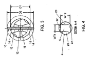
- FIG. 3 is a front end view of the drill bit of FIG. 1 ;
- FIG. 4 is a cross-sectional plane view of the drill bit of FIG. 1 taken through section A-A;
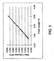
- FIG. 5 is a chart illustrating the relationship between different pitch lengths and web thickness for a drill bit as shown and described below.
- the drill bit 2 has an axially-elongated, generally cylindrical body 4, and includes a shank 6 positioned at a proximal end 8 of the body 4 and a cutting insert 10 at an opposite distal end 12 thereof.
- the body 4 preferably has a diameter D1 ( FIG. 3 ) that is slightly smaller than a hole to be drilled, and preferably is of a length that is longer than the depth of a hole to be drilled.
- the cutting insert 10 facilitates the drilling of masonry or other material, and, by way of example, may be used with a rotary drill.
- the cutting insert 10 includes a carbide plate 11 adapted for chipping or breaking up the masonry during the reciprocating action of the rotary drill.
- the carbide plate 11 includes a pair of faces 14, each of which defines a cutting edge 15.
- the faces 14 are angled with respect to each other such that the intersection of the faces 14 forms a diagonal drilling edge 16 for forming a hole in the material being drilled.
- the faces 14 define an included angle or point angle ⁇ (alpha) of approximately 120 degrees, as shown in FIG. 2 .
- the carbide plate 11 is preferably secured in the second end of the body 4 of the drill bit 2 by soldering or brazing.
- the insert 10 has a diameter D2 that is larger than the diameter D1 of the body 4 such that the diameter of a hole cut by the cutting insert 10 will be larger than the diameter D1 of the body 4.
- the shank 6 is adapted to be releasably clamped in a chuck of a power tool (not shown), such as a rotary drill.
- a power tool such as a rotary drill.
- the shank 6 is formed or machined into or from the body 4 at the proximal end 8 thereof.
- the shank 6 may be round and may be releasably clamped in the chuck.
- the shank 6 may have one or more flat outer surfaces so as to define a non-circular profile adapted to be releasably clamped in the chuck.
- the shank 6 may include a cavity that receives a mating member of the chuck.
- the shank 6 may have any suitable shape in order to efficiently facilitate its use with a chuck.
- the body 4 includes two pairs of helically-shaped grooves or flutes 20, 22 formed thereon for drilling masonry and other hard materials.
- the flutes 20, 22 may be formed, for example, through milling or forging. Also, the flutes 20, 22 may extend substantially along the length of the body 4 between the shank 6 and the cutting insert 10, and terminate adjacent the cutting insert 10.
- Each of the flutes 20, 22 extends at a predetermined angle of inclination 24 relative to a longitudinal axis 7 of the body 4 and defines a pitch length PL, as shown in FIGS. 1 and 2 .
- the pitch length PL of a flute is the distance between successive points of one complete turn of the flute about the longitudinal axis 7 of the body 4, for example, as shown in FIG. 2 .
- different angles of inclination 24 correspond to different pitch lengths PL.
- the flutes 20, 22 have the same angle of inclination 24, and thus define a common pitch length PL for the drill bit 2.
- the angle of inclination 24 for the flutes 20, 22 may be different for different bit types.
- the two pairs of flutes 20, 22 preferably have widths w1, w2 that are different from each other, but the flutes of each pair have approximately the same width. More preferably, the width w1 of the primary flutes 20 is greater than the width w2 of the secondary flutes 22.
- the primary flutes 20 are the leading flutes out of the front of the carbide tip 11 and facilitate the discharge of drilling debris as the drill bit 2 is rotated. Therefore, the primary flutes 20 are made sufficiently wide to facilitate removing drilling debris out of a hole during a drilling operation.
- the width w1 of the primary flutes 20 may vary with the bit diameter D1 so as to provide additional capacity for debris removal for larger diameter drill bits.
- the secondary flutes 22 are formed behind the primary flutes 20 to reduce the contact area between the body 4 of the drill bit 2 and material being drilled. In this way, the secondary flutes 22 act as a "shoulder" to reduce friction and heat buildup.
- the width w1 of the primary flutes 20 and the width w2 of the secondary flutes 22 will vary proportionally with the bit diameter D1.
- the drill bit 2 also includes a web 5 disposed between the flutes 20, 22, as shown in FIG. 4 .
- the web 5 corresponds generally to a longitudinally extending core portion of the body 4 that separates the flutes 20, 22.
- the web 5 has at least one web thickness, which refers to the smallest distance between two flutes of a bit.
- a small web thickness WT1 refers to the width of the web 5 separating the pair of wider primary flutes 20
- a large web thickness WT2 refers to the width of the web 5 separating the pair of narrower secondary flutes 22.
- the drill bit 2 has a pitch length PL that is in the range of about 0.67 to 3.20 inches.
- Four-fluted drill bits having a pitch length PL in this range advantageously remove drilling debris at a rate faster than bits with shorter pitch lengths during generally horizontal drilling, for example, in brick, mortar and cinder block.
- the faster rate of removal in turn, further reduces friction and heat buildup that may occur during drilling.
- reducing the drill bit's exposure to friction and heat buildup can extend the life of the bit and result in faster drilling times.
- the ratio between the large web thickness WT2 and the small web thickness WT1 is preferably about 0.66, and the large web thickness WT2 varies with the pitch length PL in an approximately linear manner such that the ratio of the large web thickness WT2 to the pitch length PL is within range of about 14 to 25 percent, as shown in Table 1 below.
- the relationship between the pitch length PL and the large web thickness WT2 for the drill bit 2 according to the present embodiment is also illustrated graphically in FIG. 5 .
Landscapes
- Engineering & Computer Science (AREA)
- Mechanical Engineering (AREA)
- Mining & Mineral Resources (AREA)
- Drilling Tools (AREA)
- Processing Of Stones Or Stones Resemblance Materials (AREA)
- Earth Drilling (AREA)
Applications Claiming Priority (1)
| Application Number | Priority Date | Filing Date | Title |
|---|---|---|---|
| US11/951,135 US20090148250A1 (en) | 2007-12-05 | 2007-12-05 | Drill Bit |
Publications (1)
| Publication Number | Publication Date |
|---|---|
| EP2067555A1 true EP2067555A1 (de) | 2009-06-10 |
Family
ID=40405323
Family Applications (1)
| Application Number | Title | Priority Date | Filing Date |
|---|---|---|---|
| EP08006582A Withdrawn EP2067555A1 (de) | 2007-12-05 | 2008-03-31 | Bohrmeißel |
Country Status (5)
| Country | Link |
|---|---|
| US (1) | US20090148250A1 (de) |
| EP (1) | EP2067555A1 (de) |
| CN (1) | CN101451426A (de) |
| AU (1) | AU2008249187A1 (de) |
| CA (1) | CA2644705A1 (de) |
Cited By (1)
| Publication number | Priority date | Publication date | Assignee | Title |
|---|---|---|---|---|
| US20240271491A1 (en) * | 2023-02-10 | 2024-08-15 | Shanghai Sutek Industries Co., Ltd. | Cement drill bit |
Families Citing this family (10)
| Publication number | Priority date | Publication date | Assignee | Title |
|---|---|---|---|---|
| USD626575S1 (en) * | 2009-08-20 | 2010-11-02 | Washington Iii Deassie | Drill bit |
| DE102011016960A1 (de) * | 2011-02-02 | 2012-08-02 | MAPAL Fabrik für Präzisionswerkzeuge Dr. Kress KG | Bohrwerkzeug und Verfahren zur Herstellung von Bohrungen |
| US20120308319A1 (en) * | 2011-06-03 | 2012-12-06 | Karthik Sampath | Rotary cutting tool having coated cutting tip and coolant holes and method of fabricating |
| ES2390324B8 (es) * | 2012-05-08 | 2013-09-10 | Univ Madrid Politecnica | Juego de brocas |
| CN102704844A (zh) * | 2012-06-20 | 2012-10-03 | 常熟市平冶机械有限公司 | 一种钣金钻头 |
| USD833490S1 (en) * | 2015-05-13 | 2018-11-13 | Diager | Drill bit |
| USD859483S1 (en) | 2016-12-06 | 2019-09-10 | Milwaukee Electric Tool Corporation | Drill bit |
| US10744671B2 (en) | 2018-03-21 | 2020-08-18 | Milwaukee Electric Tool Corporation | Auger |
| GB2574652A (en) * | 2018-06-14 | 2019-12-18 | Black & Decker Inc | Drilling tool |
| DE102020208607A1 (de) * | 2020-07-09 | 2022-01-13 | Robert Bosch Gesellschaft mit beschränkter Haftung | Einsatzwerkzeug |
Citations (3)
| Publication number | Priority date | Publication date | Assignee | Title |
|---|---|---|---|---|
| US2370706A (en) * | 1943-11-29 | 1945-03-06 | Rudolf W Andreasson | Drill |
| EP1506830A1 (de) * | 2003-08-12 | 2005-02-16 | BLACK & DECKER INC. | Eine Schneidplatte für ein Bohrwerkzeug |
| EP1849955A1 (de) * | 2006-04-28 | 2007-10-31 | HILTI Aktiengesellschaft | Drehschlagbohrer mit viergängigem Bohrwendelschaft |
Family Cites Families (32)
| Publication number | Priority date | Publication date | Assignee | Title |
|---|---|---|---|---|
| US2728558A (en) * | 1952-06-26 | 1955-12-27 | New England Carbide Tool Compa | Masonry drill |
| US2779366A (en) * | 1954-07-21 | 1957-01-29 | Clarence M Mckenzie | Quick acting c-clamp |
| US2902260A (en) * | 1957-07-16 | 1959-09-01 | Carl V Tilden | Drill bit |
| DE1602003B1 (de) * | 1966-06-08 | 1971-03-11 | Netherlands Tool Mfg Co | Gesteinsbohrer |
| US3447616A (en) * | 1966-12-29 | 1969-06-03 | Zigmund E Granat | Drills |
| US4314616A (en) * | 1980-01-28 | 1982-02-09 | Acme-Cleveland Corporation | Die-cast masonry drill with leading hard insert |
| DE3317989A1 (de) * | 1983-05-18 | 1984-11-22 | Hawera Probst Gmbh + Co, 7980 Ravensburg | Bohrwerkzeug |
| US4696377A (en) * | 1985-09-27 | 1987-09-29 | Ltv Energy Products Company | Brake system for drawworks |
| DE3707798A1 (de) * | 1987-03-11 | 1988-09-22 | Hawera Probst Kg Hartmetall | Gesteinsbohrer |
| DE3834675A1 (de) * | 1988-10-12 | 1990-04-19 | Hawera Probst Kg Hartmetall | Bohrwerkzeug |
| US5015128A (en) * | 1990-03-26 | 1991-05-14 | Ross Jr Donald C | Rotary drill apparatus |
| DE4338667A1 (de) * | 1993-11-12 | 1995-05-18 | Hilti Ag | Bohrwerkzeug |
| DE4419641A1 (de) * | 1994-06-04 | 1995-12-07 | Hilti Ag | Gesteinsbohrer |
| DE4442266A1 (de) * | 1994-11-28 | 1996-05-30 | Hilti Ag | Werkzeug mit Trägerkörper und Schneidkörper |
| TW299385B (en) * | 1994-12-12 | 1997-03-01 | Black & Decker Inc | Cutting tools for drilling concrete, aggregate, masonry or the like materials |
| US5630478A (en) * | 1995-06-07 | 1997-05-20 | Credo Tool Company | Masonry drill bit and method of making a masonry drill bit |
| DE19522033A1 (de) * | 1995-06-17 | 1996-12-19 | Hilti Ag | Verfahren zur Herstellung von Drehbohrwerkzeugen |
| US5893688A (en) * | 1996-08-08 | 1999-04-13 | Credo Tool Company | Masonry drill bit |
| DE19650487A1 (de) * | 1996-12-05 | 1998-06-10 | Hilti Ag | Bohrwerkzeug |
| DE19724373A1 (de) * | 1997-06-10 | 1998-12-17 | Hilti Ag | Gesteinsbohrer |
| US5865571A (en) * | 1997-06-17 | 1999-02-02 | Norton Company | Non-metallic body cutting tools |
| DE19753731A1 (de) * | 1997-12-04 | 1999-06-10 | Hawera Probst Gmbh | Gesteinsbohrwerkzeug |
| US6161633A (en) * | 1998-02-03 | 2000-12-19 | Cutting Edge Technology | Apparatus for boring through a solid material |
| US6736226B2 (en) * | 1998-02-03 | 2004-05-18 | Cutting Edge Technologies, Llc | Method and apparatus for boring through a solid material |
| DE19841978C2 (de) * | 1998-09-14 | 2000-11-23 | Heller Dinklage Gmbh Geb | Bohrer |
| DE19942987A1 (de) * | 1999-09-09 | 2001-03-15 | Hilti Ag | Bohrwerkzeug |
| DE10011108A1 (de) * | 2000-03-09 | 2001-09-13 | Hawera Probst Gmbh | Gesteinsbohrer |
| FR2808462B1 (fr) * | 2000-05-05 | 2002-09-20 | Diager | Foret de percage |
| DE10024433A1 (de) * | 2000-05-19 | 2001-11-29 | Hawera Probst Gmbh | Gesteinsbohrer |
| US6419561B1 (en) * | 2000-10-05 | 2002-07-16 | Kennametal Inc. | Method and apparatus for making a cutting tool having a plurality of margins |
| GB2393681A (en) * | 2002-10-03 | 2004-04-07 | Black & Decker Inc | Masonry drilling tool |
| DE102005014422B4 (de) * | 2005-03-24 | 2019-10-24 | EMUGE-Werk Richard Glimpel GmbH & Co. KG Fabrik für Präzisionswerkzeuge | Bohrgewindefräser |
-
2007
- 2007-12-05 US US11/951,135 patent/US20090148250A1/en not_active Abandoned
-
2008
- 2008-03-31 EP EP08006582A patent/EP2067555A1/de not_active Withdrawn
- 2008-04-25 CN CN200810089247.XA patent/CN101451426A/zh active Pending
- 2008-11-24 AU AU2008249187A patent/AU2008249187A1/en not_active Abandoned
- 2008-11-25 CA CA002644705A patent/CA2644705A1/en not_active Abandoned
Patent Citations (3)
| Publication number | Priority date | Publication date | Assignee | Title |
|---|---|---|---|---|
| US2370706A (en) * | 1943-11-29 | 1945-03-06 | Rudolf W Andreasson | Drill |
| EP1506830A1 (de) * | 2003-08-12 | 2005-02-16 | BLACK & DECKER INC. | Eine Schneidplatte für ein Bohrwerkzeug |
| EP1849955A1 (de) * | 2006-04-28 | 2007-10-31 | HILTI Aktiengesellschaft | Drehschlagbohrer mit viergängigem Bohrwendelschaft |
Cited By (1)
| Publication number | Priority date | Publication date | Assignee | Title |
|---|---|---|---|---|
| US20240271491A1 (en) * | 2023-02-10 | 2024-08-15 | Shanghai Sutek Industries Co., Ltd. | Cement drill bit |
Also Published As
| Publication number | Publication date |
|---|---|
| CN101451426A (zh) | 2009-06-10 |
| CA2644705A1 (en) | 2009-06-05 |
| AU2008249187A1 (en) | 2009-06-25 |
| US20090148250A1 (en) | 2009-06-11 |
Similar Documents
| Publication | Publication Date | Title |
|---|---|---|
| US20090148250A1 (en) | Drill Bit | |
| US6021857A (en) | Drill bit | |
| EP1512476B1 (de) | Selbstzentrierendes Bohrwerkzeug mit Pilotschneidteil | |
| US9878379B2 (en) | Cutting tool with enhanced chip evacuation capability and method of making same | |
| CN102802851B (zh) | 开孔工具 | |
| EP0761927B1 (de) | Steinbohrer | |
| US20080152438A1 (en) | Ballnose end mill | |
| CN108472745B (zh) | 具有断屑器的钻头和在钻头中激光切割断屑器的方法 | |
| US20010000224A1 (en) | Cutting tools for drilling concrete, aggregate, masonry or the like materials | |
| CN1556734A (zh) | 钻头的切削尖端 | |
| US7401667B2 (en) | Multi-purpose drilling tool | |
| CN1200790C (zh) | 一种加工刀片的方法 | |
| US9981406B2 (en) | Drill bit | |
| CN1307361C (zh) | 钻头 | |
| EP0761353B1 (de) | Bohrer | |
| AU782364B2 (en) | Perforating drill | |
| CN1241237A (zh) | 钻岩机 | |
| JP2010201565A (ja) | エンドミル | |
| KR101278927B1 (ko) | 절삭 판을 포함하는 확공기 | |
| JP2007044833A (ja) | 回転切削工具 | |
| KR101822517B1 (ko) | 스텝 드릴 비트 | |
| TW201039948A (en) | Drilling tool | |
| US20250121441A1 (en) | Drill bit tip and drill with drill bit tip, mold and method for manufacturing drill bit tip | |
| CN101166885A (zh) | 钻孔工具 | |
| RU2183721C2 (ru) | Бур-расширитель |
Legal Events
| Date | Code | Title | Description |
|---|---|---|---|
| PUAI | Public reference made under article 153(3) epc to a published international application that has entered the european phase |
Free format text: ORIGINAL CODE: 0009012 |
|
| AK | Designated contracting states |
Kind code of ref document: A1 Designated state(s): AT BE BG CH CY CZ DE DK EE ES FI FR GB GR HR HU IE IS IT LI LT LU LV MC MT NL NO PL PT RO SE SI SK TR |
|
| AX | Request for extension of the european patent |
Extension state: AL BA MK RS |
|
| AKX | Designation fees paid | ||
| REG | Reference to a national code |
Ref country code: DE Ref legal event code: 8566 |
|
| STAA | Information on the status of an ep patent application or granted ep patent |
Free format text: STATUS: THE APPLICATION IS DEEMED TO BE WITHDRAWN |
|
| 18D | Application deemed to be withdrawn |
Effective date: 20091211 |