EP2067556A2 - Werkzeughaltevorrichtung - Google Patents
Werkzeughaltevorrichtung Download PDFInfo
- Publication number
- EP2067556A2 EP2067556A2 EP08170819A EP08170819A EP2067556A2 EP 2067556 A2 EP2067556 A2 EP 2067556A2 EP 08170819 A EP08170819 A EP 08170819A EP 08170819 A EP08170819 A EP 08170819A EP 2067556 A2 EP2067556 A2 EP 2067556A2
- Authority
- EP
- European Patent Office
- Prior art keywords
- tool
- main body
- holder device
- support plane
- rotation
- Prior art date
- Legal status (The legal status is an assumption and is not a legal conclusion. Google has not performed a legal analysis and makes no representation as to the accuracy of the status listed.)
- Withdrawn
Links
Images



Classifications
-
- B—PERFORMING OPERATIONS; TRANSPORTING
- B23—MACHINE TOOLS; METAL-WORKING NOT OTHERWISE PROVIDED FOR
- B23B—TURNING; BORING
- B23B31/00—Chucks; Expansion mandrels; Adaptations thereof for remote control
- B23B31/02—Chucks
- B23B31/36—Chucks with means for adjusting the chuck with respect to the working-spindle
-
- B—PERFORMING OPERATIONS; TRANSPORTING
- B23—MACHINE TOOLS; METAL-WORKING NOT OTHERWISE PROVIDED FOR
- B23B—TURNING; BORING
- B23B31/00—Chucks; Expansion mandrels; Adaptations thereof for remote control
- B23B31/02—Chucks
- B23B31/10—Chucks characterised by the retaining or gripping devices or their immediate operating means
- B23B31/12—Chucks with simultaneously-acting jaws, whether or not also individually adjustable
- B23B31/19—Chucks with simultaneously-acting jaws, whether or not also individually adjustable moving parallel to the axis of the chuck
-
- B—PERFORMING OPERATIONS; TRANSPORTING
- B23—MACHINE TOOLS; METAL-WORKING NOT OTHERWISE PROVIDED FOR
- B23C—MILLING
- B23C5/00—Milling-cutters
- B23C5/26—Securing milling cutters to the driving spindle
-
- B—PERFORMING OPERATIONS; TRANSPORTING
- B24—GRINDING; POLISHING
- B24B—MACHINES, DEVICES, OR PROCESSES FOR GRINDING OR POLISHING; DRESSING OR CONDITIONING OF ABRADING SURFACES; FEEDING OF GRINDING, POLISHING, OR LAPPING AGENTS
- B24B41/00—Component parts such as frames, beds, carriages, headstocks
- B24B41/04—Headstocks; Working-spindles; Features relating thereto
- B24B41/042—Balancing mechanisms
-
- B—PERFORMING OPERATIONS; TRANSPORTING
- B24—GRINDING; POLISHING
- B24B—MACHINES, DEVICES, OR PROCESSES FOR GRINDING OR POLISHING; DRESSING OR CONDITIONING OF ABRADING SURFACES; FEEDING OF GRINDING, POLISHING, OR LAPPING AGENTS
- B24B45/00—Means for securing grinding wheels on rotary arbors
-
- B—PERFORMING OPERATIONS; TRANSPORTING
- B27—WORKING OR PRESERVING WOOD OR SIMILAR MATERIAL; NAILING OR STAPLING MACHINES IN GENERAL
- B27B—SAWS FOR WOOD OR SIMILAR MATERIAL; COMPONENTS OR ACCESSORIES THEREFOR
- B27B5/00—Sawing machines working with circular or cylindrical saw blades; Components or equipment therefor
- B27B5/29—Details; Component parts; Accessories
- B27B5/30—Details; Component parts; Accessories for mounting or securing saw blades or saw spindles
- B27B5/32—Devices for securing circular saw blades to the saw spindle
-
- B—PERFORMING OPERATIONS; TRANSPORTING
- B27—WORKING OR PRESERVING WOOD OR SIMILAR MATERIAL; NAILING OR STAPLING MACHINES IN GENERAL
- B27B—SAWS FOR WOOD OR SIMILAR MATERIAL; COMPONENTS OR ACCESSORIES THEREFOR
- B27B5/00—Sawing machines working with circular or cylindrical saw blades; Components or equipment therefor
- B27B5/29—Details; Component parts; Accessories
- B27B5/30—Details; Component parts; Accessories for mounting or securing saw blades or saw spindles
- B27B5/32—Devices for securing circular saw blades to the saw spindle
- B27B5/325—Devices for securing circular saw blades to the saw spindle using fluid pressure means
-
- B—PERFORMING OPERATIONS; TRANSPORTING
- B23—MACHINE TOOLS; METAL-WORKING NOT OTHERWISE PROVIDED FOR
- B23B—TURNING; BORING
- B23B2250/00—Compensating adverse effects during turning, boring or drilling
- B23B2250/04—Balancing rotating components
-
- B—PERFORMING OPERATIONS; TRANSPORTING
- B23—MACHINE TOOLS; METAL-WORKING NOT OTHERWISE PROVIDED FOR
- B23C—MILLING
- B23C2260/00—Details of constructional elements
- B23C2260/04—Adjustable elements
Definitions
- the present invention concerns a tool-holder device suitable to couple a circular type tool to the shaft of a motor able to make it rotate, according to the pre-amble to claim 1, as known for example from EP-B-0.592.694 .
- the tool-holder device according to the invention is applied particularly, but not exclusively, to tools used in working wood or plastic materials, such as for example circular toothed milling cutters or suchlike.
- Circular type tools are known, usually consisting of a disk having work elements on its periphery, for example teeth, serrations or suchlike, and axially a hole for insertion on a support element that couples them with the shaft of the motor that makes them rotate.
- This positioning is normally entrusted to tight coupling tolerances provided between the tool and the device, and between the device and the drive shaft.
- This erroneous positioning can distort the adjustment of the position made, and can lead to the tool becoming jammed on the relative positioning hub provided on the tool-holder device.
- One purpose of the present invention is to achieve a tool-holder device which allows to perform easy and rapid adjustment operations both on the work plane of the tool with respect to the drive shaft, and also the concentric position of the axis of rotation of the tool with the axis of rotation of the drive shaft.
- Another purpose of the present invention is to achieve a tool-holder device that allows to perform a repeatability over time of the positioning of the tool.
- Another purpose is to achieve a tool-holder device that reduces to a minimum the risk of an inclined positioning of the tool on the tool-holder device itself.
- the Applicant has devised, tested and embodied the present invention to overcome the shortcomings of the state of the art and to obtain these and other purposes and advantages.
- a tool-holder device comprises a main body of the flange type, having an axial hole able to couple with the rotation shaft of the machine on which the tool is to be mounted.
- the main body defines a support plane on which the circular tool, for example a toothed milling cutter or other similar or comparable tool, is keyed and clamped, by clamping means.
- the circular tool for example a toothed milling cutter or other similar or comparable tool
- annular support element attached to the main body by means of clamping screws and to which, in turn, the tool is attached by means of the clamping means.
- the tool-holder device also comprises a plurality of cuneiform adjustment means, distributed on the circumference of the main body.
- the cuneiform means are able to be displaced radially so as to act on a mating inclined surface of a relative seat made on the main body, in a direction slightly inclined with respect to the orthogonal to the axis of rotation.
- the cuneiform means are associated with adjustment means accessible from the outside, and allow to perform adjustment and fine balancing operations of the position of the support plane on which the tool is clamped, with respect to its axis of rotation.
- the main body of the tool-holder device comprises a plurality of elastic adjustment means distributed on the circumference of the main body, substantially equidistant from each other, and advantageously alternated with the cuneiform adjustment means.
- the elastic adjustment means are able to be actuated radially in a direction substantially orthogonal with respect to the axis of rotation of the rotation shaft.
- the elastic adjustment means comprise relative thrust means, for example screws, accessible from the outside, which act on a coordinated, elastically yielding surface made on the main body.
- the elastic adjustment means it is possible to perform the desired centering adjustments of the axis of rotation of the tool, irrespective of the accuracy of the coupling tolerance between the tool-holder device and the rotation shaft.
- the elastic adjustment means ensure that there is a constant connection force between the elements of the tool-holder device, which prevents the formation of play that can trigger vibrations or loosening.
- the thrust means each comprise a movable ball and an adjustment screw, inserted into mating seatings made on the external periphery of a relative annular element mounted on the main body.
- the elastic thrust means also comprise elastic members associated with the seating, and able to cooperate with the movable ball and the adjustment screw, in order to exert the radial thrust on the coordinated surface of the main body.
- the elastically yielding surface is made in the seating.
- the elastically yielding surface is associated with springs, for example cup springs, disposed in the seating.
- the elastically yielding surface extends on a substantial part of the segment of drive shaft disposed inside the device.
- the main body comprises a conical surface for coupling with the tool.
- the surface is advantageously conformed so as to allow a precise coupling of the tool and the tool-holder device, substantially eliminating possible play, and guaranteeing the repeatability of positioning of the tool with respect to the tool-holder device.
- the main body is associated, on the opposite side with respect to the position of the tool, with a circular covering flange.
- the flange has at least a housing groove for balancing elements, such as small masses or suchlike, the angular position of which can be modified so as guarantee the constant balancing of the whole tool-holder device.
- the clamping means comprise a plurality of actuator members mounted mobile on the main body, commanded simultaneously and able to cooperate with the tool, so as to define the attachment thereof to the main body.
- the actuator members are selectively movable in simultaneous manner between a first positioning condition, in which they protrude from the support plane of the main body and keep the tool in a condition separate from the main body, and a second attachment condition in which they are retracted toward the main body with respect to the support plane and keep the tool perfectly adherent to at least said support plane.
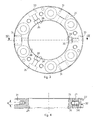
- a tool-holder device is denoted generally by the reference number 10, and is used to support and make a circular tool 11, such as a toothed cutter or suchlike, only partly shown in fig. 1 , rotate according to an axis 30.
- the tool-holder device 10 comprises a main body 12, in this case made in two parts, respectively a first part 13 and a second part 15, coaxially coupled with each other due to same shape coupling and reciprocally attached by means of screws, not shown, to define substantially a single element.
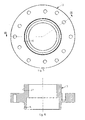
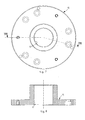
- the first part 13 ( figs. 5 and 6 ) comprises a support plane "P" on which the circular tool 11 is rested, a coupling shoulder 16 on which the circular tool 11 is keyed and clamped, whereas the second part 15 ( figs. 7 and 8 ) defines an axial hole 17 in which a drive shaft 19 is inserted and clamped.
- the main body 12 is made as a single element provided both with the coupling shoulder 16, and with the axial hole 17 and also with the support plane "P".
- the coupling shoulder 16 has a certain taper, so as to define a conical coupling between the main body 12 and the circular tool 11.
- the taper allows to reduce, if not eliminate, the coupling play between the device 10 and the tool 11, allowing an optimum repeatability of the positioning of the tool 11.
- the taper provided for the coupling shoulder 16 is comprised in a range of values from about 1:5 to about 1:15, advantageously about 1:10.
- the circular tool 11 is clamped directly on the first part 13 by a plurality of attachment screws 20.
- the circular tool 11 is clamped to the main body 12 not directly, but by means of an annular support element, not shown.
- the main body 12 also comprises an annular adjustment element 21 disposed in a coordinated circular seating 22 defined by the coupling of the first part 13 and the second part 15.
- the annular adjustment element 21 comprises an internal circular surface 26, able to contact a corresponding support surface 27 of the first part 13.
- the annular adjustment element 21 comprises three conical blocks 29, or wedges, inserted into mating seats 31made on the external periphery of the main body 12, and able to allow the selective adjustment of the position of the support plane P for the tool 11.
- the conical blocks 29 in this case are distributed at 120° on the circumference of the main body 12, and are operatively associated with respective cup springs, so that each time we act in a radial direction on the adjustment screws, to modify the position of the support plane P for the tool 11 with respect to the axis of rotation 30, the elastic, not rigid connection of the main body 12 and the second part 15 allows to adapt to the new position without needing to act and operate on the attachment screws 19.
- the annular adjustment element 21 also comprises three adjustment elements 32, in this case each provided with a thrust unit 34 consisting in this case of a movable ball and an adjustment screw, inserted into mating seatings 33 made on the external periphery of the main body 12.
- the three adjustment elements 32 are distributed at 120° on the circumference of the main body 12, in alternate positions with respect to the conical blocks 29.
- Each seating 33 has a yielding terminal part 35, made in a piece from the annular adjustment element 21 and elastically constrained to the latter.
- the terminal part 35 comprises externally a thrust surface 36, able to contact the support surface 27 of the first part 13.
- the terminal part 35 is able to be thrust from the inside toward the outside against the support surface 27 by the relative adjustment element 32.
- each adjustment element 32 allows to selectively adjust, also micrometrically, the reciprocal position of the axis of rotation 30 of the drive shaft 19 and the axis of rotation of the circular tool 11.
- each thrust surface 36 determines a thrusting action on the drive shaft 19 for the whole contact zone with the axial hole 17.
- a circular covering flange 23 ( figs. 9 and 10 ), attached to the second part of the main body 12 by screws.
- the covering flange 23 not only protects the holes in the main body 12 where the screws 19 are inserted from the infiltration of dust, oil or other dirt, but also has the function of housing a plurality of masses, displaceable angularly so as to balance the weight of the whole tool unit.
- a groove 25 concentric with the axis of the flange 23 and able to house small masses that can be moved and clamped in a defined angular position.
- the main body in this case indicated by the reference number 112, is made as two parts, respectively a first 113 and a second 115.
- the first part 113 and the second part 115 are coupled coaxially with each other.
- first part 113 is conformed substantially as a cross, while the second part 115 comprises coordinated positioning seatings 36, in which the arms of the first part 113 are housed.
- first part 113 and the second part 115 define the support plane P for the circular tool 11.
- the conical blocks 29 and the mating seats 31 are mounted and made on the main body 112 while the adjustment elements 32 are made on the second part 115.
- the covering flange 123 is hollow internally and inside it a movement ring 37 is mounted, axially mobile.
- the movement ring 37 defines a sealed pneumatic chamber with the covering flange 123.
- actuator blocks 40 are provided, driven pneumatically, disposed substantially parallel to the axis of rotation 30, passing through the second part 115 and constrained with one end to the movement ring 37.
- each actuator block 40 comprises a constraining groove 41 and a rounded terminal 42, which normally protrude from the second part 115 with respect to the support plane P.
- corresponding constraining eyelets 45 are made on the circular tool 11, conformed with a variable width to allow a bayonet type attachment with respect to the constraining groove 41 and rounded terminal 42 of each actuator block 40.
- Each actuator block 40 is mechanically associated with a respective elastic element, in this case cup springs 43, which tends to normally keep the relative actuator block 40 in a retracted condition, that is, prevalently inside the first part 115.
- the actuator blocks 40 are in fact selectively movable in a direction substantially parallel to the axis of rotation 30 between a first positioning condition ( fig. 13 ), and a second attachment condition ( fig. 14 ).
- the actuator blocks 40 protrude from the support plane P of the main body 112 and allow bayonet type attachment with the circular tool 11. In this condition, the actuator blocks 40 protrude in such a manner as to keep the circular tool 11 in proximity with, but separate from, the support plane P and also the coupling shoulder 16.
- the actuator blocks 40 In the second attachment condition, the actuator blocks 40, due to the effect of the action of the cup springs 43, simultaneously retreat toward the main body 112, taking the circular tool 11, with a movement substantially parallel to the axis of rotation 30, to rest on the support plane P.
- the circular tool 11 is taken to adhere perfectly both to the support plane P and also to the coupling shoulder 16, guaranteeing that the adjustment made with the conical blocks 29 and the adjustment element 32 are respected.
- elastic thrust elements are provided such as cup springs, foil springs, leaf springs, helical springs, or others suitable for the purpose.
- the main body 12 does not have the annular adjustment element 21.
- the conical blocks 29 and the adjustment elements 32 are provided directly on the first part 13, or on the second part 15 of the main body 12.
Landscapes
- Engineering & Computer Science (AREA)
- Mechanical Engineering (AREA)
- Life Sciences & Earth Sciences (AREA)
- Wood Science & Technology (AREA)
- Forests & Forestry (AREA)
- Physics & Mathematics (AREA)
- Fluid Mechanics (AREA)
- Gripping On Spindles (AREA)
- Jigs For Machine Tools (AREA)
- Cutting Tools, Boring Holders, And Turrets (AREA)
Applications Claiming Priority (1)
| Application Number | Priority Date | Filing Date | Title |
|---|---|---|---|
| ITUD20070231 ITUD20070231A1 (it) | 2007-12-05 | 2007-12-05 | Dispositivo portautensili |
Publications (2)
| Publication Number | Publication Date |
|---|---|
| EP2067556A2 true EP2067556A2 (de) | 2009-06-10 |
| EP2067556A3 EP2067556A3 (de) | 2010-01-20 |
Family
ID=40315952
Family Applications (1)
| Application Number | Title | Priority Date | Filing Date |
|---|---|---|---|
| EP08170819A Withdrawn EP2067556A3 (de) | 2007-12-05 | 2008-12-05 | Werkzeughaltevorrichtung |
Country Status (2)
| Country | Link |
|---|---|
| EP (1) | EP2067556A3 (de) |
| IT (1) | ITUD20070231A1 (de) |
Cited By (2)
| Publication number | Priority date | Publication date | Assignee | Title |
|---|---|---|---|---|
| WO2013041567A1 (en) * | 2011-09-19 | 2013-03-28 | Schaublin Sa | Adjustable clamping device |
| CN112792625A (zh) * | 2021-01-11 | 2021-05-14 | 张永霞 | 一种铣刀刃磨机工件紧固辅助组件 |
Citations (1)
| Publication number | Priority date | Publication date | Assignee | Title |
|---|---|---|---|---|
| EP0592694B1 (de) | 1992-10-07 | 1996-12-27 | METAL WORLD s.n.c. di PAVIOTTI & C. | Werkzeughalter für einen ringförmigen einstellbaren Fräser |
Family Cites Families (8)
| Publication number | Priority date | Publication date | Assignee | Title |
|---|---|---|---|---|
| DE938875C (de) * | 1953-01-01 | 1956-02-09 | Rolf Geiger | Anordnung zur Befestigung und Sicherung von Fraeserkoerpern und Einzelfraesern, insbesondere Tassenfraesern an diesen, bei Holzbearbeitungsmaschinen |
| US2803928A (en) * | 1954-07-06 | 1957-08-27 | Everite Machine Products Compa | Wheel truing device |
| US2841929A (en) * | 1956-12-26 | 1958-07-08 | Super Cut | Truing device for peripheral type grinding wheels |
| SU766845A1 (ru) * | 1973-04-23 | 1980-09-30 | Ордена Трудового Красного Знамени Институт Сверхтвердых Материалов Ан Украинской Сср | Устройство дл установки шлифовального круга |
| DE2320919C2 (de) * | 1973-04-25 | 1991-06-20 | Ledermann Gmbh + Co, 7240 Horb | Schnellwechsel-Spannvorrichtung für Rotationswerkzeuge, insbesondere für Kreissägen |
| EP0268104A1 (de) * | 1986-10-22 | 1988-05-25 | Gühring Automation GmbH & Co | Schleifscheibenanordnung für eine Hochgeschwindigkeits-Schleifmaschine |
| JPH02130715U (de) * | 1989-03-31 | 1990-10-29 | ||
| ITUD20020112A1 (it) * | 2002-05-23 | 2003-11-24 | Metal World Spa | Dispositivo portautensili |
-
2007
- 2007-12-05 IT ITUD20070231 patent/ITUD20070231A1/it unknown
-
2008
- 2008-12-05 EP EP08170819A patent/EP2067556A3/de not_active Withdrawn
Patent Citations (1)
| Publication number | Priority date | Publication date | Assignee | Title |
|---|---|---|---|---|
| EP0592694B1 (de) | 1992-10-07 | 1996-12-27 | METAL WORLD s.n.c. di PAVIOTTI & C. | Werkzeughalter für einen ringförmigen einstellbaren Fräser |
Cited By (5)
| Publication number | Priority date | Publication date | Assignee | Title |
|---|---|---|---|---|
| US9248508B2 (en) | 2011-06-19 | 2016-02-02 | Schaublin Sa | Adjustable clamping device |
| WO2013041567A1 (en) * | 2011-09-19 | 2013-03-28 | Schaublin Sa | Adjustable clamping device |
| WO2013041118A1 (en) * | 2011-09-19 | 2013-03-28 | Schaublin Sa | Adjustable clamping device |
| AU2012311558B2 (en) * | 2011-09-19 | 2016-12-15 | Schaublin Sa | Adjustable clamping device |
| CN112792625A (zh) * | 2021-01-11 | 2021-05-14 | 张永霞 | 一种铣刀刃磨机工件紧固辅助组件 |
Also Published As
| Publication number | Publication date |
|---|---|
| ITUD20070231A1 (it) | 2009-06-06 |
| EP2067556A3 (de) | 2010-01-20 |
Similar Documents
| Publication | Publication Date | Title |
|---|---|---|
| KR20150017727A (ko) | 모듈형 공구 리테이너 | |
| KR101128235B1 (ko) | 회전수단을 가지는 연마가공물 고정용 지그 | |
| KR20010098530A (ko) | 기계 가공용 커터 플레이트 및 절삭 공구 | |
| EP2067556A2 (de) | Werkzeughaltevorrichtung | |
| EP2654995B1 (de) | Schneidwerkzeug mit einem auf dem schaft montierten verstellring | |
| CZ200578A3 (cs) | Zařízení pro připevnění držáku nástroje | |
| US6053678A (en) | Rotary tool holder with a balance device | |
| US2524468A (en) | Chuck | |
| CN209272507U (zh) | 无心车床刀盘 | |
| US20130104706A1 (en) | Method for processing an inner face of a housing having an opening | |
| CN210435387U (zh) | 一种内孔外圆可替换镗刀装置 | |
| US20070045970A1 (en) | Diaphragm chuck | |
| KR102536273B1 (ko) | 절삭 공구 | |
| JP2018525237A (ja) | 特には孔を精密加工するためのリーマ工具である機械工具 | |
| JPH0271996A (ja) | 工具の迅速脱着装置 | |
| US8348557B2 (en) | Cutting head for a milling machine for manufacturing ophthalmic lenses made of plastic | |
| JP2021522080A (ja) | 深さストッパ付き切削工具 | |
| US4573837A (en) | Longitudinal feed attachment for a boring bar | |
| KR20200036878A (ko) | 절삭 공구 및 조절 장치가 장착된 절삭 공구를 위한 조절 장치 | |
| KR20190001384U (ko) | 선반의 래비린스 시일 가공용 바이트구조체 | |
| EP1536916B1 (de) | Eine inhärent ausgeglichene spindel für werkzeugköpfe zum eichen, glätten oder polieren von steinplatten und/oder von keramikfliesen | |
| JPS62157710A (ja) | カツタ−装置 | |
| CN109862980B (zh) | 具有位置校正功能的作业机械和该作业机械的位置校正方法 | |
| CN210818759U (zh) | 超声波刀柄 | |
| US2855731A (en) | Truing device for peripheral type grinding wheels |
Legal Events
| Date | Code | Title | Description |
|---|---|---|---|
| PUAI | Public reference made under article 153(3) epc to a published international application that has entered the european phase |
Free format text: ORIGINAL CODE: 0009012 |
|
| AK | Designated contracting states |
Kind code of ref document: A2 Designated state(s): AT BE BG CH CY CZ DE DK EE ES FI FR GB GR HR HU IE IS IT LI LT LU LV MC MT NL NO PL PT RO SE SI SK TR |
|
| AX | Request for extension of the european patent |
Extension state: AL BA MK RS |
|
| PUAL | Search report despatched |
Free format text: ORIGINAL CODE: 0009013 |
|
| RIC1 | Information provided on ipc code assigned before grant |
Ipc: B23B 31/36 20060101ALI20091209BHEP Ipc: B24B 41/04 20060101ALI20091209BHEP Ipc: B24B 45/00 20060101ALI20091209BHEP Ipc: B27B 5/32 20060101ALI20091209BHEP Ipc: B23B 31/19 20060101ALI20091209BHEP Ipc: B23B 31/02 20060101ALI20091209BHEP Ipc: B23C 5/26 20060101AFI20090331BHEP |
|
| AK | Designated contracting states |
Kind code of ref document: A3 Designated state(s): AT BE BG CH CY CZ DE DK EE ES FI FR GB GR HR HU IE IS IT LI LT LU LV MC MT NL NO PL PT RO SE SI SK TR |
|
| AX | Request for extension of the european patent |
Extension state: AL BA MK RS |
|
| 17P | Request for examination filed |
Effective date: 20100714 |
|
| AKX | Designation fees paid |
Designated state(s): AT BE BG CH CY CZ DE DK EE ES FI FR GB GR HR HU IE IS IT LI LT LU LV MC MT NL NO PL PT RO SE SI SK TR |
|
| STAA | Information on the status of an ep patent application or granted ep patent |
Free format text: STATUS: THE APPLICATION IS DEEMED TO BE WITHDRAWN |
|
| 18D | Application deemed to be withdrawn |
Effective date: 20150701 |