EP2067581B1 - Kabelbetriebenes Manipuliergerät mit einer Kabelkompensationsvorrichtung - Google Patents
Kabelbetriebenes Manipuliergerät mit einer Kabelkompensationsvorrichtung Download PDFInfo
- Publication number
- EP2067581B1 EP2067581B1 EP08021101A EP08021101A EP2067581B1 EP 2067581 B1 EP2067581 B1 EP 2067581B1 EP 08021101 A EP08021101 A EP 08021101A EP 08021101 A EP08021101 A EP 08021101A EP 2067581 B1 EP2067581 B1 EP 2067581B1
- Authority
- EP
- European Patent Office
- Prior art keywords
- pulley
- cable
- forearm
- rotating body
- upper arm
- Prior art date
- Legal status (The legal status is an assumption and is not a legal conclusion. Google has not performed a legal analysis and makes no representation as to the accuracy of the status listed.)
- Not-in-force
Links
Images


Classifications
-
- B—PERFORMING OPERATIONS; TRANSPORTING
- B25—HAND TOOLS; PORTABLE POWER-DRIVEN TOOLS; MANIPULATORS
- B25J—MANIPULATORS; CHAMBERS PROVIDED WITH MANIPULATION DEVICES
- B25J9/00—Program-controlled manipulators
- B25J9/10—Program-controlled manipulators characterised by positioning means for manipulator elements
- B25J9/104—Program-controlled manipulators characterised by positioning means for manipulator elements with cables, chains or ribbons
- B25J9/1045—Program-controlled manipulators characterised by positioning means for manipulator elements with cables, chains or ribbons comprising tensioning means
-
- Y—GENERAL TAGGING OF NEW TECHNOLOGICAL DEVELOPMENTS; GENERAL TAGGING OF CROSS-SECTIONAL TECHNOLOGIES SPANNING OVER SEVERAL SECTIONS OF THE IPC; TECHNICAL SUBJECTS COVERED BY FORMER USPC CROSS-REFERENCE ART COLLECTIONS [XRACs] AND DIGESTS
- Y10—TECHNICAL SUBJECTS COVERED BY FORMER USPC
- Y10T—TECHNICAL SUBJECTS COVERED BY FORMER US CLASSIFICATION
- Y10T74/00—Machine element or mechanism
- Y10T74/20—Control lever and linkage systems
- Y10T74/20207—Multiple controlling elements for single controlled element
- Y10T74/20305—Robotic arm
- Y10T74/20323—Robotic arm including flaccid drive element
Definitions
- the present invention relates to a cable-driven manipulator, more specifically to a cable-driven manipulator, in which a cable compensation device is installed between an upper arm and a forearm to be configured in such a way that the length of a cable wound on the pulley provided in the operating unit to operate an end effector is maintained constantly even during the pivoting of the forearm, so that it is possible to prevent the variation of tensile force due to the variation of the length of the cable for operating the end effector during the pivoting of the forearm or the unintended malfunction of the end effector.
- a master-slave manipulator is widely used as replacements for human workers in hazardous environment.
- the dimensions (length, thickness, size, etc.) of the manipulator are designed according to work content and workspace.
- Transmission systems driven by cables and pulleys are generally used as power transmission system of manipulators, robots, and mechatronic equipment.
- the force-reflecting master-slave manipulator used in a radioactive environment transmits power usually by using a tendon like cable such as steel cable or tape.
- actuators can be installed far away from joints or links, the weight or inertia of a manipulator arm can be reduced. Therefore, small capacity actuators can be used and accordingly the dynamic performance of the system can be improved.
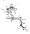
- Fig. 1 is a cross sectional view showing a conventional cable-driven manipulator
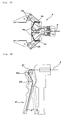
- Fig. 2A is a cross sectional view showing a gripper of an end-effector in a conventional cable-driven manipulator
- Fig. 2B is a schematic view showing a handle of an end-effector in a conventional cable-driven manipulator
- Figs. 3A and 3B are schematic views showing the states of the cable wound on the upper arm and the forearm, when the forearm of the conventional cable-driven manipulator is at the neutral position and when it is pivoting, respectively.
- a conventional cable-driven manipulator comprises on operating unit 1 having a drive motor (actuator) 1a, bevel gears and a pulley 1b which interlock with the drive.motor 1a; an upper arm 2 one end of which is jointly coupled to the operating unit 1 and is pivoted by power transmitted from the operating unit 1 through a cable 5; a forearm 3 one end of which is jointly coupled to the other end of the upper arm 2 and is pivoted by the cable 5; and a gripper 4 which is an end-effector jointly coupled to the other end of the forearm 3 and is operated by the cable 5.
- actuator drive motor
- pulley 1b which interlock with the drive.motor 1a
- an upper arm 2 one end of which is jointly coupled to the operating unit 1 and is pivoted by power transmitted from the operating unit 1 through a cable 5
- a forearm 3 one end of which is jointly coupled to the other end of the upper arm 2 and is pivoted by the cable 5
- a gripper 4 which is an end-effector jointly coupled to the
- the cable 5 is guided over several pulleys coupled to the pivoted joint and transmits the power of the drive motor 1a to the gripper 4.
- the gripper 4 makes motions of roll, pitch, yaw, grip, etc. by the cable 5 that passes through the inside of the upper arm 2 and the forearm 3.
- the drive motor 1a when the drive motor 1a is rotated, the chain 4a installed in the gripper 4 is pulled by the cable 5 wound on the axis of bevel gear, thus the links 4b are rotated so that the gripper 4 is operated to be closed.
- the drive motor 1a is rotated in an opposite direction, the cable 5 is unwound so that the gripper 4 is operated to be opened by the elastic return force of springs 4c installed in the gripper 4.
- the gripper 4 is one of end effectors used in the slave of the cable-driven manipulator.
- a handle 8 shown in Fig. 2B can be used as an end effector of the master manipulator that has the same configuration as the slave manipulator.
- the cable 5 is wound on a handle pulley 8a installed at one end 8' of the handle 8 before it is fixed at the other end 8" of the handle 8 via a pivot 8b.
- the handle 8 also makes a swing motion centering on the pivot 8b by the tension of the cable 5 according to the forward or reverse rotation of the drive motor 1a.
- gripper 4 and the handle 8 are different in use, they are identical in that both are end effectors of the cable-driven manipulator operated by the tension of the cable 5.
- a second pulley 7 which is an idle pulley supporting a first pulley 6 and the cable 5.
- One end B of the cable 5 is operatively connected to the drive motor 1a, and the other end A of the cable 5 is operatively connected to the gripper 4.
- the position of B is moved left and right.
- Such a position change of the cable 5 changes the position of the other end A of the cable 5 via the first pulley 6 and the second pulley 7, and thus the opening and closing actions of the gripper 4 are performed.
- the forearm 3 is rotated counterclockwise by a predetermined angle ⁇ , the total length of the cable from B to A is increased by a predetermined length (the radius r of the first pulley 6 x predetermined angle ⁇ ) compared with the reference position. Inversely, if the forearm 3 is rotated clockwise, the total length of the cable is decreased by a predetermined length (the radius r of the first pulley 6 x predetermined angle ⁇ ).
- the conventional cable-driven manipulator as described above can generate the interference phenomenon which causes the opening and closing action of the gripper 4 or the swing action of the handle 8 that was not intended during the pivoting of the upper arm 2, owing to the geometrical cable-pulley configurations.
- such an interference phenomenon can give rise to a problem that the gripped object can fall down when the cable 5 driving the gripper 4 is unwound or on the contrary the gripped object can be damaged due to excessive tensile force.
- Document US-A-3,335,620 discloses the features of the preamble of present claim 1.
- this document discloses an articulation device with two arms being coupled to each other for transmission of movements by means of cables, belts or chains.
- a link rod connecting the two arms is provided as cable compensation device there between, i.e. between an upper arm and a forearm.
- This additional link between the upper arm and forearm serves to maintain constantly the length of the flexible transmission means that transmits the power of an operating unit to an end effector also during the pivoting of the forearm.
- a cable-driven manipulator comprising: an operating unit having a drive motor, and a pulley which is rotated by the drive motor; an upper arm which is jointly coupled to one side of the operating unit by the power transmitted from the operating unit by a cable; a forearm which is jointly coupled to the other side of the upper arm by the power transmitted from the operating unit by the cable; an end-effector which is operatably coupled to the forearm by the cables; and a cable compensation device which is installed between the upper arm and the forearm so as to constantly maintain the length of the cable that transmits the power of the operating unit to the end-effector during the pivoting of the forearm.
- the cable compensation device comprises a first pulley mounted on a first axis fixed to the upper arm where the upper arm and the forearm are jointly coupled; a first rotating body installed integratedly to the first pulley so as to be interlocked with the forearm; a third pulley mounted on a third axis separated at a predetermined interval horizontally lengthwise of the upper arm in the first rotating body; a second rotating body installed integratedly to the third pulley so as to be interlocked with the first rotating body; and a second pulley mounted on the second axis that is inserted in a slot formed between the first pulley and the third pulley so that it can be moved lengthwise of the upper arm, and on which is wound a cable separately from the first pulley and the third pulley respectively, a fourth pulley mounted on the first axis on which the first pulley is mounted; a fifth pulley mounted on the second axis on which the second pulley is mounted; and at least one sixth pulleys installed on the
- the respective rotation centers of the first, second and third pulleys may be arranged in a straight line.
- first rotating body and the second rotating body may be interlocked by links connected pivotably therewith.
- first rotating body of an extended plate shape may have one side of it coupled to the forearm and the other side pivotably coupled to the first axis
- second rotating body of the extended plate shape may be pivotably coupled to the third axis to which the third pulley is coupled, and these first and second rotating bodies are pivotably connected by a link.
- the fifth pulley may move along an imaginary line connecting the rotation center of the fourth pulley and the rotation center of the fifth pulley, and the sixth pulley is placed so as to be in parallel with an imaginary line connecting the rotation center of the fourth pulley and the rotation center of the fifth pulley, and the cable is wound on the fifth pulley by n ⁇ 1/2 rotations (wherein, n is a natural number).
- the radiuses of the fourth and fifth pulleys and the radiuses of the first, second and third pulleys is all the same.
- the manipulator may further comprise a third rotating body of a plate shape which is installed at the other end of the upper arm in separation at a predetermined interval lengthwise from the second rotating body and is coupled to the first rotating body through the link so as to interlock therewith.
- the end-effector may be a gripper jointly coupled to the forearm or a handle coupled to the forearm.
- the cable-driven manipulator according to the present invention has advantages that it is possible to prevent variation of tensile force due to variation of the length of the cable for operating the end-effector during the pivoting of the forearm and that precise position control of the end-effector is possible.
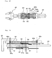
- Figs. 4A and 4B are a perspective view and a plan view showing the cable-driven manipulator according a preferred embodiment of the present invention, respectively
- Fig. 5A is a plan view schematically showing the operation of the cable-driven manipulator according to the preferred embodiment of the present invention
- Fig. 5B and 5C are lateral views schematically showing the operation of the cable-driven manipulator according to the preferred embodiment of the present invention, respectively
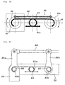
- Figs. 6A to 6D are schematic views showing various arrangements of the fourth to sixth pulleys provided in the cable-driven manipulator according to the preferred embodiment of the present invention.
- the cable-driven manipulator comprises an operating unit 10 having a drive motor 12 and a pulley 16 which is rotated by the drive motor 12, an upper arm 20 which is jointly coupled to the one side of the operation unit 10, a forearm 30 which is jointly coupled to the other side of the upper arm 20, an end-effector which is jointly coupled to the forearm 30, and a cable compensation device 80 which is installed between the upper arm 20 and the forearm 30 so as to constantly maintain the length of the cable 50 that transmits the power of the operating unit. 10 to the end-effector during the pivoting of the forearm 30.
- a speed reducer 14 may be installed between the drive motor 12 and the pulley 16.
- the present invention has main interest in the cable compensation device 80 that constantly maintains the length of the cable 50 driving the end-effector of the manipulator also during the pivoting of the forearm, it should be noted that detailed descriptions for the components related to the drive motor and cable for motions of roll, pitch, yaw, etc. of the upper arm and the forearm of the manipulator were omitted so as not to obscure the purport of the present invention.
- the cable-driven manipulator configured as described above transmits the power of the operating unit 10 to the gripper 40, which is an end-effector, by the cable 50 that passes through the inside of the upper arm 20 and the forearm 30, to make the motions of roll, pitch, yaw, grip, etc. of the gripper 40 possible.
- the cable compensation device 80 that constantly maintains the length of the cable 50 for the motion of the gripper 40. Therefore, the variation of tensile force due to the variation of the length of the cable 50 that operates the gripper 40 or unintended malfunction of the gripper 40 is also prevented during the pivoting of the forearm 30, and precise position control of the gripper 40 becomes possible.
- the cable compensation device 80 includes, as shown in Fig. 5A and Fig. 5B , a first pulley 83 mounted on a first axis 89a fixed to the upper arm 20 where the upper arm 20 and the forearm 30 are jointly coupled, a first rotating body 86a installed integratedly to the first pulley 83 so as to interlock with the forearm 30, a third pulley 85 separated at a predetermined interval lengthwise of the upper arm 20 from the first rotating body 86a and installed in the upper arm 20, and a second rotating body 86b installed integratedly to the third pulley 85.
- the second rotating body 86b and the first rotating body 86a are pivotably connected by the link 88 so as to interlock with each other.
- a second axis 89b that is movable left or right lengthwise of the upper arm 20 is inserted into a slot 81a formed between the first pulley 83 and the third pulley 85.
- a second pulley 84 operated by the first pulley 83 and the third pulley 85 and cables wound independently of each other.
- the first rotating body 86a is fixed to the forearm 30, and is rotated at the same angle with the rotation of the forearm 30.
- All of the first, second and third pulleys 83, 84 and 85 have equal radiuses, and the rotation centers of the pulleys 83, 84 and 85 can be arranged in a straight line.
- the first rotating body 86a of an extended plate shape has one side which is coupled to the forearm 30 and the other side which is coupled to the first axis 89a and formed with an extended plate therefrom.
- the second rotating body 86b also with an extended plate shape can be pivotably coupled to the third axis 89c having the third pulley 85 coupled therewith.
- the link 88 is connected pivotably to the first and second rotating bodies 86a and 86b of a plate shape respectively to interlock these.
- first rotating body 86a and the second rotating body 86b were illustrated and described in a configuration in which they are connected by the link 88 so as to be interlocked with each other.
- first rotating body 86a and the second rotating body 86b are wound with one cable to be interlocked with each other, or such a configuration in which the first rotating body 86a and the second rotating body 86b are formed with sprockets and a chain is wound on the sprockets of the first rotating body 86a and the second rotating body 86b to be interlocked with each other is also possible.
- the cable compensation device 80 further comprises, as shown in Fig. 5A and Fig. 6A , a fourth pulley 70 mounted on the first axis 89a on which the first pulley 83 is mounted, and a fifth pulley 81 mounted so as to be interlocked with the second pulley 84 on the second axis 89b on which the second pulley 84 is mounted.
- a sixth pulleys 82 is an idle pulley, which is arranged in such a way that the cable 50 wound on the fifth pulley 81 is maintained horizontally lengthwise of the upper arm 20.
- the cable 50 wound on the pulley 16 provided in the operating unit 10 is wound on the fourth, fifth and sixth pulleys 70, 81 and 82 before it is connected to the gripper 40 to transmit power.
- the fourth and sixth pulleys 70 and 82 are fixed pulleys
- the fifth pulley 81 mounted on the second axis 89b is a movable pulley that moves left or right in proportion to the rotation quantity of the forearm 30.
- the fourth and fifth pulleys 70 and 81 have the same radiuses each other, and these pulleys 70 and 81 have the same radiuses with the first, second and third pulleys 83, 84, and 85. Therefore, the first to fifth pulleys 83, 84, 85, 70 and 81 have all the same radiuses.
- the second pulley 84 mounted on the second axis 89b movably installed in the upper arm 20 moves left or right in correspondence to the rotation of the forearm 30, and accordingly the fifth pulley 81 mounted on the second axis 89b movably installed in the upper arm 20 moves left or right, so that the length variation of the cable 50 by the rotation of the forearm 30 is compensated.
- the first and second rotating bodies 86a and 86b are interlocked with each other.
- the first rotating body 86a and the second rotating body 86b of the mechanical configuration like above rotate also in the same direction through the link 88.
- the cable wound between the first pulley 83 and the second pulley 84 arranged on the first axis 89a in which the first rotating body 86a is installed is unwound, and the cable wound between the third pulley 85 and the second pulley 84 arranged on the third axis 89c in which the second rotating body 86b is installed is wound.
- the second pulley 84 which is a movable pulley, is moved in the right direction in the drawing.
- the diameters of the first, second and third pulleys 83, 84 and 85 are the same, so if the first rotating body 86a rotates by a predetermined angle 8, the second pulley 84 makes linear motion to the right as much as a predetermined length (radius r of the first pulley 83 x predetermined angle ⁇ /2).
- the second pulley 84 which is a movable pulley, makes linear motion to the left as much as the predetermined length (radius r of the first pulley 83 x predetermined angle ⁇ /2).
- the fifth pulley 81 connected on the same axis (i.e. the second axis 89b) as the second pulley 84 makes linear motion likewise. Since the first to fifth pulleys 83, 84, 85, 70 and 81 all have the same radius, the fifth pulley 81 also makes linear motion as much as the predetermined length (radius r of the first pulley 83 x predetermined angle ⁇ /2).
- the cable 50 that is wound on the fifth pulley 81 and connected to the gripper 40 of the end-effector has the length changed as much as the predetermined length (radius r of the first pulley 83 x predetermined angle ⁇ /2) at two places (where the cable comes in and goes out of the fifth pulley), so the length of the cable 50 at the gripper 40 of the end-effector is compensated finally as much as the predetermined length (radius r of the first pulley 83 x predetermined angle ⁇ ).
- the length of the cable 50 can be maintained constantly even if the fourth pulley 70 coupled on the first axis 89a between the upper arm 20 and the forearm 30 rotates, so it is possible to remove the interference phenomenon due to the operation of the manipulator.
- a third rotating body 86c of a plate shape at the other end of the upper arm 20.
- the third rotating body 86c is installed in separation at a predetermined interval lengthwise from the second rotating body 86b.
- the third rotating body 86c is coupled to the first rotating body 86a through the link 80 so as to interlock therewith (see Fig. 4A ).
- the third rotating body 86c plays a role of transmitting the rotation force of a separately installed driving unit to the forearm 30 through the link mechanism to pivot the forearm 30.
- Figs. 6B to 6D show various examples of applicable arrangements besides the arrangement of the fourth, fifth and sixth pulleys 70, 81 and 82 illustrated in Fig. 6A .
- the present invention can be figured variously like arranging the fourth, fifth and sixth pulleys 70, 81 and 82 inside the upper arm 20.
- Fig. 6A and Fig. 6B shows the case of one idle pulley, the sixth pulley 82, and
- Fig. 6C and 6D shows the case of two idle pulleys, the sixth pulleys 82 and 82'.
- These examples are the arrangements that satisfy two conditions. Any arrangement that satisfies the two conditions to be described in detail below has the identical effects.
- the first condition for the arrangement of the fourth, fifth and sixth pulleys 70, 81 and 82 is that the fifth pulley 81 should move on an imaginary line connecting the rotation centers of the fourth and fifth pulleys 70 and 81.
- both ends of the cable 50 wound on the fifth pulley 81 should be in parallel with an imaginary line connecting the rotation centers of the fourth and fifth pulleys 70 and 81.
- the cable 50 is wound on the fifth pulley 81 by n ⁇ 1/2 rotations (wherein, n is a natural number). That is, the cable 50 should have its direction of motion changed 180° after it is wound on the fifth pulley 81.
- the linearly moved length of the fifth pulley 81 can be reflected on the gripper 40 of the end-effector as it is.
- the number and position of the idle pulleys, the sixth pulleys 82 and 82', and the sequence in which the cable 50 is wound on the fourth, fifth and sixth pulleys 70, 81, and 82 have no effect on the action of the cable-driven manipulator according to the present invention.
- the drive motor 12 can be installed away from the jointly coupled portion of the upper arm 20 and the forearm 30, so it is possible to reduce the weight or inertia of the upper arm 20 or the forearm 30 of the manipulator. Therefore, it is possible to use the drive motor 12 of small capacity, and accordingly it is possible to improve the dynamic performance of the cable-driven manipulator and the durability of related parts.
Landscapes
- Engineering & Computer Science (AREA)
- Robotics (AREA)
- Mechanical Engineering (AREA)
- Manipulator (AREA)
Claims (8)
- Seilgetriebener Manipulator, der umfasst:- eine Betätigungseinheit (10) mit einem Antriebsmotor (12) und einer Riemenscheibe (16), die durch den Antriebsmotor (12) gedreht wird;- einen oberen Arm (20), der mit einer Seite der Betätigungseinheit (10) durch die Kraft, die von der Betätigungseinheit übertragen wird, gelenkig gekoppelt ist;- einen vorderen Arm, der mit der anderen Seite des oberen Arms durch die Kraft, die von der Betätigungseinheit (10) übertragen wird, gelenkig gekoppelt ist; und- einen Endeffektor, der mit dem vorderen Arm (30) betriebstechnisch gekoppelt ist; und- eine Seilausgleichsvorrichtung (80), die zwischen dem oberen Arm (20) und dem vorderen Arm (30) installiert ist, um die Länge des Seils (30), das die Kraft der Betätigungseinheit (10) an den Endeffektor überträgt, auch während des Schwenkens des vorderen Arms (30) konstant zu halten,
dadurch gekennzeichnet, dass die Seilausgleichsvorrichtung umfasst: eine erste Riemenscheibe (83), die an der ersten Welle (89a) montiert ist, die am oberen Arm (20) dort befestigt ist, wo der obere Arm (20) und der vordere Arm (30) gelenkig gekoppelt sind;- einen ersten Drehkörper (86a), der an der ersten Riemenscheibe (83) einteilig installiert ist, um mit dem vorderen Arm (30) verriegelt zu sein;- eine dritte Riemenscheibe (85), die an einer dritten Welle (89c) montiert ist und um ein vorgegebenes Intervall horizontal in Längsrichtung des oberen Arms (20) in dem ersten Drehkörper (86a) beabstandet ist;- einen zweiten Drehkörper (86b), der an der dritten Riemenscheibe (85) einteilig installiert ist, um mit dem ersten Drehkörper (86a) verriegelt zu sein;- eine zweite Riemenscheibe (84), die an einer zweiten Welle montiert ist, die in einen Schlitz eingesetzt ist, der zwischen der ersten Riemenscheibe (83) und der dritten Riemenscheibe (85) ausgebildet ist, so dass sie in Längsrichtung des oberen Arms (20) bewegt werden kann, und auf die ein Seil getrennt von der ersten Riemenscheibe (83) bzw. der dritten Riemenscheibe (85) gewickelt ist;- eine vierte Riemenscheibe (70), die an der ersten Welle (89a) montiert ist, an der die erste Riemenscheibe (83) montiert ist;- eine fünfte Riemenscheibe (81), die an der zweiten Welle montiert ist, an der die zweite Riemenscheibe (84) montiert ist; und- wenigstens eine sechste Riemenscheibe, die am oberen Arm (20) installiert ist, so dass das Seil von der in der Betätigungseinheit (10) vorgesehenen Riemenscheibe abgewickelt und auf die fünfte Riemenscheibe (81) aufgewickelt wird und horizontal in Längsrichtung des oberen Abends (20) gehalten wird, und
wobei die erste, die zweite und die dritte Riemenscheibe (83, 84, 85) alle denselben Radius haben. - Manipulator nach Anspruch 1, wobei die jeweiligen Drehzentren der ersten, der zweiten und der dritten Riemenscheibe (83, 84, 85) auf einer geraden Linie angeordnet sind.
- Manipulator nach Anspruch 1, wobei der erste Drehkörper (86a) und der zweite Drehkörper (86b) durch Gestänge, die damit schwenkbar verbunden sind, verriegelt sind.
- Manipulator nach Anspruch 3, wobei der erste Drehkörper (86a) in Form einer lang gestreckten Platte mit einer Seite mit dem vorderen Arm (30) gekoppelt und mit der anderen Seite mit der ersten Welle (89a) schwenkbar gekoppelt ist und der zweite Drehkörper (86b) in Form einer lang gestreckten Platte mit der dritten Welle (89c), mit der die dritte Riemenscheibe (85) gekoppelt ist, schwenkbar gekoppelt ist, wobei dieser erste und dieser zweite Drehkörper (86a, 86b) durch ein Gestänge (88) schwenkbar verbunden sind.
- Manipulator nach Anspruch 1, wobei sich die fünfte Riemenscheibe (81) längs einer imaginären Linie bewegt, die das Drehzentrum der vierten Riemenscheibe (70) und das Drehzentrum der fünften Riemenscheibe (81) verbindet, und die sechste Riemenscheibe (82) so angeordnet ist, dass sie zu einer imaginären Linie parallel ist, die das Drehzentrum der vierten Riemenscheibe (70) und das Drehzentrum der fünften Riemenscheibe (81) verbindet, und das Seil (50) auf die fünfte Riemenscheibe (81) durch n ± 1/2 Umdrehungen (wobei n eine natürliche Zahl ist) gewickelt wird.
- Manipulator nach einem der Ansprüche 1 bis 5, wobei die Radien der vierten und der fünften Riemenscheibe (70, 81) und die Radien der ersten, der zweiten und der dritten Riemenscheibe (83, 84, 85) alle gleich sind.
- Manipulator nach einem der Ansprüche 1 bis 6, der ferner einen dritten Drehkörper (86c) in Form einer Platte umfasst, der am anderen Ende des oberen Arms (20) in Längsrichtung um ein vorgegebenes Intervall beabstandet von dem zweiten Drehkörper (86b) installiert ist und mit dem ersten Drehkörper (86a) über ein Gestänge (80) gekoppelt ist, um damit verriegelt zu sein.
- Manipulator nach Anspruch 1, wobei der Endeffektor ein Greifer (40) ist, der mit dem vorderen Arm (30) gelenkig gekoppelt ist, oder ein Haltegriff ist, der mit dem vorderen Arm (30) gekoppelt ist.
Applications Claiming Priority (2)
| Application Number | Priority Date | Filing Date | Title |
|---|---|---|---|
| KR20070125586 | 2007-12-05 | ||
| KR1020080112545A KR101038473B1 (ko) | 2007-12-05 | 2008-11-13 | 케이블 구동 매니퓰레이터 |
Publications (2)
| Publication Number | Publication Date |
|---|---|
| EP2067581A1 EP2067581A1 (de) | 2009-06-10 |
| EP2067581B1 true EP2067581B1 (de) | 2011-01-12 |
Family
ID=40386382
Family Applications (1)
| Application Number | Title | Priority Date | Filing Date |
|---|---|---|---|
| EP08021101A Not-in-force EP2067581B1 (de) | 2007-12-05 | 2008-12-04 | Kabelbetriebenes Manipuliergerät mit einer Kabelkompensationsvorrichtung |
Country Status (2)
| Country | Link |
|---|---|
| US (1) | US8083460B2 (de) |
| EP (1) | EP2067581B1 (de) |
Cited By (1)
| Publication number | Priority date | Publication date | Assignee | Title |
|---|---|---|---|---|
| CN110663358A (zh) * | 2019-09-29 | 2020-01-10 | 山东大学 | 一种基于线驱动调节倾角的机械臂及果品采摘装置 |
Families Citing this family (16)
| Publication number | Priority date | Publication date | Assignee | Title |
|---|---|---|---|---|
| US6902560B1 (en) | 2000-07-27 | 2005-06-07 | Intuitive Surgical, Inc. | Roll-pitch-roll surgical tool |
| KR101706094B1 (ko) * | 2010-01-14 | 2017-02-14 | 삼성전자주식회사 | 로봇용 관절 구동장치 및 이를 포함하는 로봇, 로봇용 관절 구동장치의 케이블 연결방법 |
| CN102166755B (zh) * | 2011-01-26 | 2012-08-22 | 东南大学 | 一种遥操作机器人的机械手末端三维接触力测量方法 |
| CN102967484A (zh) * | 2012-10-31 | 2013-03-13 | 东南大学 | 一种小行星岩石采样机械臂装置 |
| KR102127215B1 (ko) * | 2013-05-07 | 2020-06-30 | 삼성전자주식회사 | 와이어 연결 장치 |
| US10076348B2 (en) | 2013-08-15 | 2018-09-18 | Intuitive Surgical Operations, Inc. | Rotary input for lever actuation |
| US10231859B1 (en) * | 2014-05-01 | 2019-03-19 | Boston Dynamics, Inc. | Brace system |
| CN105583851B (zh) * | 2016-03-21 | 2017-06-20 | 哈尔滨工业大学 | 一种利用钢丝传动锥形盘输出式旋转关节 |
| CN105598999B (zh) * | 2016-03-21 | 2018-01-30 | 哈尔滨工业大学 | 一种利用钢丝驱动的阶梯凸轮输出式旋转关节 |
| WO2018094191A1 (en) * | 2016-11-21 | 2018-05-24 | Intuitive Surgical Operations, Inc. | Cable length conserving medical instrument |
| US20180264660A1 (en) * | 2017-03-20 | 2018-09-20 | Kindred Systems Inc. | Systems, devices, articles, and methods for prehension |
| CN107901032B (zh) * | 2017-09-26 | 2020-11-20 | 南京航空航天大学 | 无摩擦的绳驱动被动解耦机构及其解耦减摩方法 |
| US10966893B2 (en) * | 2018-03-23 | 2021-04-06 | Hiwin Technologies Corp. | Exoskeleton apparatus for limb rehabilitation |
| CN108674640B (zh) * | 2018-04-08 | 2021-06-15 | 南京航空航天大学 | 一种旋翼飞行机器人 |
| CN113729951B (zh) * | 2021-10-12 | 2023-08-29 | 中南大学 | 手术机器人的双平行四边形初调机构 |
| CN114406999B (zh) * | 2022-02-11 | 2023-11-21 | 吉林大学 | 一种绳驱同轴人工肌肉执行器及其控制方法 |
Family Cites Families (6)
| Publication number | Priority date | Publication date | Assignee | Title |
|---|---|---|---|---|
| FR1375031A (fr) | 1963-05-10 | 1964-10-16 | Commissariat Energie Atomique | Dispositifs d'articulation avec transmission de mouvements |
| FR2278457A1 (fr) * | 1974-07-18 | 1976-02-13 | Commissariat Energie Atomique | Manipulateur motorise a cables |
| FR2434685A1 (fr) * | 1978-09-04 | 1980-03-28 | Commissariat Energie Atomique | Manipulateur motorise |
| US4259876A (en) * | 1979-10-02 | 1981-04-07 | Belyanin Petr N | Mechanical arm |
| US4883400A (en) * | 1988-08-24 | 1989-11-28 | Martin Marietta Energy Systems, Inc. | Dual arm master controller for a bilateral servo-manipulator |
| US7469617B2 (en) * | 2004-07-22 | 2008-12-30 | Honda Motor Co., Ltd. | Tension compensating assembly for mechanical control cables |
-
2008
- 2008-12-04 EP EP08021101A patent/EP2067581B1/de not_active Not-in-force
- 2008-12-05 US US12/328,792 patent/US8083460B2/en active Active
Cited By (1)
| Publication number | Priority date | Publication date | Assignee | Title |
|---|---|---|---|---|
| CN110663358A (zh) * | 2019-09-29 | 2020-01-10 | 山东大学 | 一种基于线驱动调节倾角的机械臂及果品采摘装置 |
Also Published As
| Publication number | Publication date |
|---|---|
| US20090148263A1 (en) | 2009-06-11 |
| US8083460B2 (en) | 2011-12-27 |
| EP2067581A1 (de) | 2009-06-10 |
Similar Documents
| Publication | Publication Date | Title |
|---|---|---|
| EP2067581B1 (de) | Kabelbetriebenes Manipuliergerät mit einer Kabelkompensationsvorrichtung | |
| CN108481311B (zh) | 一种变刚度柔顺抓取装置 | |
| US4903536A (en) | Compact cable transmission with cable differential | |
| US5207114A (en) | Compact cable transmission with cable differential | |
| US5046375A (en) | Compact cable transmission with cable differential | |
| JP5265635B2 (ja) | 腱駆動型指作動システム | |
| KR101038473B1 (ko) | 케이블 구동 매니퓰레이터 | |
| KR101862023B1 (ko) | 적응형 파지가 가능한 로봇 핸드용 그리퍼 | |
| US7950710B2 (en) | Robot | |
| KR102009291B1 (ko) | 로봇 관절 장치 | |
| KR20100067275A (ko) | 로봇 | |
| US8776632B2 (en) | Low-stroke actuation for a serial robot | |
| WO2018033716A1 (en) | An Improved Gripper | |
| CN114131644A (zh) | 机械手 | |
| CN118769277A (zh) | 灵巧手拇指、灵巧手和机器人 | |
| JP5082037B2 (ja) | ロボットハンド | |
| EP0111069B1 (de) | Antrieb für Robotergreifer | |
| KR101814926B1 (ko) | 원격제어 매니퓰레이터 장치의 와이어 케이블 장력 저감장치 | |
| JP3777783B2 (ja) | 水平アームを有するロボット | |
| JP7653868B2 (ja) | ロボットハンドおよびロボットシステム | |
| KR102782209B1 (ko) | 웨어러블 로봇용 케이블 구동 회전 관절 장치 | |
| JP6687928B2 (ja) | 関節駆動装置及び多軸マニュピレータ | |
| CN116922424A (zh) | 一种柔索全驱动仿人灵巧手手指机构 | |
| JP4124232B2 (ja) | 水平アームを有するロボット | |
| KR20120034324A (ko) | 모션 비간섭 케이블 구동장치 |
Legal Events
| Date | Code | Title | Description |
|---|---|---|---|
| PUAI | Public reference made under article 153(3) epc to a published international application that has entered the european phase |
Free format text: ORIGINAL CODE: 0009012 |
|
| AK | Designated contracting states |
Kind code of ref document: A1 Designated state(s): AT BE BG CH CY CZ DE DK EE ES FI FR GB GR HR HU IE IS IT LI LT LU LV MC MT NL NO PL PT RO SE SI SK TR |
|
| AX | Request for extension of the european patent |
Extension state: AL BA MK RS |
|
| RIN1 | Information on inventor provided before grant (corrected) |
Inventor name: LEE, JONG KWANG Inventor name: LEE, HYO JIK Inventor name: YOON, JI SUP Inventor name: YOON, KWANG HO Inventor name: CHOI, CHANG HWAN Inventor name: PARK, BYUNG SUK |
|
| 17P | Request for examination filed |
Effective date: 20091130 |
|
| 17Q | First examination report despatched |
Effective date: 20100112 |
|
| AKX | Designation fees paid |
Designated state(s): DE FR |
|
| GRAP | Despatch of communication of intention to grant a patent |
Free format text: ORIGINAL CODE: EPIDOSNIGR1 |
|
| GRAS | Grant fee paid |
Free format text: ORIGINAL CODE: EPIDOSNIGR3 |
|
| GRAA | (expected) grant |
Free format text: ORIGINAL CODE: 0009210 |
|
| AK | Designated contracting states |
Kind code of ref document: B1 Designated state(s): DE FR |
|
| REF | Corresponds to: |
Ref document number: 602008004415 Country of ref document: DE Date of ref document: 20110224 Kind code of ref document: P |
|
| REG | Reference to a national code |
Ref country code: DE Ref legal event code: R096 Ref document number: 602008004415 Country of ref document: DE Effective date: 20110224 |
|
| PLBE | No opposition filed within time limit |
Free format text: ORIGINAL CODE: 0009261 |
|
| STAA | Information on the status of an ep patent application or granted ep patent |
Free format text: STATUS: NO OPPOSITION FILED WITHIN TIME LIMIT |
|
| 26N | No opposition filed |
Effective date: 20111013 |
|
| REG | Reference to a national code |
Ref country code: DE Ref legal event code: R097 Ref document number: 602008004415 Country of ref document: DE Effective date: 20111013 |
|
| REG | Reference to a national code |
Ref country code: FR Ref legal event code: PLFP Year of fee payment: 8 |
|
| REG | Reference to a national code |
Ref country code: FR Ref legal event code: PLFP Year of fee payment: 9 |
|
| PGFP | Annual fee paid to national office [announced via postgrant information from national office to epo] |
Ref country code: FR Payment date: 20160923 Year of fee payment: 9 |
|
| PGFP | Annual fee paid to national office [announced via postgrant information from national office to epo] |
Ref country code: DE Payment date: 20160921 Year of fee payment: 9 |
|
| REG | Reference to a national code |
Ref country code: DE Ref legal event code: R119 Ref document number: 602008004415 Country of ref document: DE |
|
| REG | Reference to a national code |
Ref country code: FR Ref legal event code: ST Effective date: 20180831 |
|
| PG25 | Lapsed in a contracting state [announced via postgrant information from national office to epo] |
Ref country code: DE Free format text: LAPSE BECAUSE OF NON-PAYMENT OF DUE FEES Effective date: 20180703 Ref country code: FR Free format text: LAPSE BECAUSE OF NON-PAYMENT OF DUE FEES Effective date: 20180102 |