EP2067590B1 - Procédé de fabrication de tuyaux composites - Google Patents
Procédé de fabrication de tuyaux composites Download PDFInfo
- Publication number
- EP2067590B1 EP2067590B1 EP20080021158 EP08021158A EP2067590B1 EP 2067590 B1 EP2067590 B1 EP 2067590B1 EP 20080021158 EP20080021158 EP 20080021158 EP 08021158 A EP08021158 A EP 08021158A EP 2067590 B1 EP2067590 B1 EP 2067590B1
- Authority
- EP
- European Patent Office
- Prior art keywords
- pipe
- tube
- concrete
- composite
- formwork
- Prior art date
- Legal status (The legal status is an assumption and is not a legal conclusion. Google has not performed a legal analysis and makes no representation as to the accuracy of the status listed.)
- Active
Links
Images

Classifications
-
- B—PERFORMING OPERATIONS; TRANSPORTING
- B28—WORKING CEMENT, CLAY, OR STONE
- B28B—SHAPING CLAY OR OTHER CERAMIC COMPOSITIONS; SHAPING SLAG; SHAPING MIXTURES CONTAINING CEMENTITIOUS MATERIAL, e.g. PLASTER
- B28B21/00—Methods or machines specially adapted for the production of tubular articles
- B28B21/56—Methods or machines specially adapted for the production of tubular articles incorporating reinforcements or inserts
- B28B21/58—Steel tubes
-
- B—PERFORMING OPERATIONS; TRANSPORTING
- B28—WORKING CEMENT, CLAY, OR STONE
- B28B—SHAPING CLAY OR OTHER CERAMIC COMPOSITIONS; SHAPING SLAG; SHAPING MIXTURES CONTAINING CEMENTITIOUS MATERIAL, e.g. PLASTER
- B28B21/00—Methods or machines specially adapted for the production of tubular articles
- B28B21/70—Methods or machines specially adapted for the production of tubular articles by building-up from preformed elements
- B28B21/72—Producing multilayer tubes
-
- B—PERFORMING OPERATIONS; TRANSPORTING
- B28—WORKING CEMENT, CLAY, OR STONE
- B28B—SHAPING CLAY OR OTHER CERAMIC COMPOSITIONS; SHAPING SLAG; SHAPING MIXTURES CONTAINING CEMENTITIOUS MATERIAL, e.g. PLASTER
- B28B21/00—Methods or machines specially adapted for the production of tubular articles
- B28B21/92—Methods or apparatus for treating or reshaping
-
- B—PERFORMING OPERATIONS; TRANSPORTING
- B32—LAYERED PRODUCTS
- B32B—LAYERED PRODUCTS, i.e. PRODUCTS BUILT-UP OF STRATA OF FLAT OR NON-FLAT, e.g. CELLULAR OR HONEYCOMB, FORM
- B32B1/00—Layered products having a non-planar shape
- B32B1/08—Tubular products
-
- B—PERFORMING OPERATIONS; TRANSPORTING
- B32—LAYERED PRODUCTS
- B32B—LAYERED PRODUCTS, i.e. PRODUCTS BUILT-UP OF STRATA OF FLAT OR NON-FLAT, e.g. CELLULAR OR HONEYCOMB, FORM
- B32B13/00—Layered products comprising a a layer of water-setting substance, e.g. concrete, plaster, asbestos cement, or like builders' material
- B32B13/04—Layered products comprising a a layer of water-setting substance, e.g. concrete, plaster, asbestos cement, or like builders' material comprising such water setting substance as the main or only constituent of a layer, which is next to another layer of the same or of a different material
- B32B13/12—Layered products comprising a a layer of water-setting substance, e.g. concrete, plaster, asbestos cement, or like builders' material comprising such water setting substance as the main or only constituent of a layer, which is next to another layer of the same or of a different material of synthetic resin
-
- B—PERFORMING OPERATIONS; TRANSPORTING
- B32—LAYERED PRODUCTS
- B32B—LAYERED PRODUCTS, i.e. PRODUCTS BUILT-UP OF STRATA OF FLAT OR NON-FLAT, e.g. CELLULAR OR HONEYCOMB, FORM
- B32B27/00—Layered products comprising a layer of synthetic resin
- B32B27/18—Layered products comprising a layer of synthetic resin characterised by the use of special additives
-
- B—PERFORMING OPERATIONS; TRANSPORTING
- B32—LAYERED PRODUCTS
- B32B—LAYERED PRODUCTS, i.e. PRODUCTS BUILT-UP OF STRATA OF FLAT OR NON-FLAT, e.g. CELLULAR OR HONEYCOMB, FORM
- B32B27/00—Layered products comprising a layer of synthetic resin
- B32B27/30—Layered products comprising a layer of synthetic resin comprising vinyl (co)polymers; comprising acrylic (co)polymers
- B32B27/304—Layered products comprising a layer of synthetic resin comprising vinyl (co)polymers; comprising acrylic (co)polymers comprising vinyl halide (co)polymers, e.g. PVC, PVDC, PVF, PVDF
-
- B—PERFORMING OPERATIONS; TRANSPORTING
- B32—LAYERED PRODUCTS
- B32B—LAYERED PRODUCTS, i.e. PRODUCTS BUILT-UP OF STRATA OF FLAT OR NON-FLAT, e.g. CELLULAR OR HONEYCOMB, FORM
- B32B27/00—Layered products comprising a layer of synthetic resin
- B32B27/32—Layered products comprising a layer of synthetic resin comprising polyolefins
-
- B—PERFORMING OPERATIONS; TRANSPORTING
- B32—LAYERED PRODUCTS
- B32B—LAYERED PRODUCTS, i.e. PRODUCTS BUILT-UP OF STRATA OF FLAT OR NON-FLAT, e.g. CELLULAR OR HONEYCOMB, FORM
- B32B3/00—Layered products comprising a layer with external or internal discontinuities or unevennesses, or a layer of non-planar shape; Layered products comprising a layer having particular features of form
- B32B3/02—Layered products comprising a layer with external or internal discontinuities or unevennesses, or a layer of non-planar shape; Layered products comprising a layer having particular features of form characterised by features of form at particular places, e.g. in edge regions
-
- F—MECHANICAL ENGINEERING; LIGHTING; HEATING; WEAPONS; BLASTING
- F16—ENGINEERING ELEMENTS AND UNITS; GENERAL MEASURES FOR PRODUCING AND MAINTAINING EFFECTIVE FUNCTIONING OF MACHINES OR INSTALLATIONS; THERMAL INSULATION IN GENERAL
- F16L—PIPES; JOINTS OR FITTINGS FOR PIPES; SUPPORTS FOR PIPES, CABLES OR PROTECTIVE TUBING; MEANS FOR THERMAL INSULATION IN GENERAL
- F16L9/00—Rigid pipes
- F16L9/08—Rigid pipes of concrete, cement, or asbestos cement, with or without reinforcement
-
- F—MECHANICAL ENGINEERING; LIGHTING; HEATING; WEAPONS; BLASTING
- F16—ENGINEERING ELEMENTS AND UNITS; GENERAL MEASURES FOR PRODUCING AND MAINTAINING EFFECTIVE FUNCTIONING OF MACHINES OR INSTALLATIONS; THERMAL INSULATION IN GENERAL
- F16L—PIPES; JOINTS OR FITTINGS FOR PIPES; SUPPORTS FOR PIPES, CABLES OR PROTECTIVE TUBING; MEANS FOR THERMAL INSULATION IN GENERAL
- F16L9/00—Rigid pipes
- F16L9/14—Compound tubes, i.e. made of materials not wholly covered by any one of the preceding groups
-
- B—PERFORMING OPERATIONS; TRANSPORTING
- B32—LAYERED PRODUCTS
- B32B—LAYERED PRODUCTS, i.e. PRODUCTS BUILT-UP OF STRATA OF FLAT OR NON-FLAT, e.g. CELLULAR OR HONEYCOMB, FORM
- B32B2262/00—Composition or structural features of fibres which form a fibrous or filamentary layer or are present as additives
- B32B2262/10—Inorganic fibres
- B32B2262/101—Glass fibres
-
- B—PERFORMING OPERATIONS; TRANSPORTING
- B32—LAYERED PRODUCTS
- B32B—LAYERED PRODUCTS, i.e. PRODUCTS BUILT-UP OF STRATA OF FLAT OR NON-FLAT, e.g. CELLULAR OR HONEYCOMB, FORM
- B32B2307/00—Properties of the layers or laminate
- B32B2307/50—Properties of the layers or laminate having particular mechanical properties
- B32B2307/54—Yield strength; Tensile strength
-
- B—PERFORMING OPERATIONS; TRANSPORTING
- B32—LAYERED PRODUCTS
- B32B—LAYERED PRODUCTS, i.e. PRODUCTS BUILT-UP OF STRATA OF FLAT OR NON-FLAT, e.g. CELLULAR OR HONEYCOMB, FORM
- B32B2307/00—Properties of the layers or laminate
- B32B2307/50—Properties of the layers or laminate having particular mechanical properties
- B32B2307/546—Flexural strength; Flexion stiffness
-
- B—PERFORMING OPERATIONS; TRANSPORTING
- B32—LAYERED PRODUCTS
- B32B—LAYERED PRODUCTS, i.e. PRODUCTS BUILT-UP OF STRATA OF FLAT OR NON-FLAT, e.g. CELLULAR OR HONEYCOMB, FORM
- B32B2307/00—Properties of the layers or laminate
- B32B2307/70—Other properties
- B32B2307/714—Inert, i.e. inert to chemical degradation, corrosion
-
- B—PERFORMING OPERATIONS; TRANSPORTING
- B32—LAYERED PRODUCTS
- B32B—LAYERED PRODUCTS, i.e. PRODUCTS BUILT-UP OF STRATA OF FLAT OR NON-FLAT, e.g. CELLULAR OR HONEYCOMB, FORM
- B32B2307/00—Properties of the layers or laminate
- B32B2307/70—Other properties
- B32B2307/732—Dimensional properties
- B32B2307/734—Dimensional stability
- B32B2307/736—Shrinkable
-
- B—PERFORMING OPERATIONS; TRANSPORTING
- B32—LAYERED PRODUCTS
- B32B—LAYERED PRODUCTS, i.e. PRODUCTS BUILT-UP OF STRATA OF FLAT OR NON-FLAT, e.g. CELLULAR OR HONEYCOMB, FORM
- B32B2597/00—Tubular articles, e.g. hoses, pipes
Definitions
- the invention relates to a method for producing composite pipes according to the preamble of claim 1.
- Simple concrete or reinforced concrete pipes are preferably produced on fully automatic systems using the so-called immediate shuttering technology.
- earth-moist concrete is compacted with high vibratory energy in a steel formwork. Subsequently, both the inner shape penetrates with additional material and thus increases the corrosion resistance.
- the composite pipe is formed by rolling up an inner layer of corrosion-resistant material.
- the problem here is that the inliners must be connected using suitable binders or adhesives with the concrete pipe.
- the processing of the binders is not easy and requires skilled personnel. If improperly executed, the inner lining of the concrete pipe can come loose, which can lead to leaks and thus to not insignificant environmental damage.
- DE 197 45 599 C2 discloses a composite tube having a concrete outer tubular member and a thermoset lining, wherein a layer of elastically deformable material is provided between the inner surface of the outer tubular member and the liner.
- the method for producing such a composite pipe provides that here too the lining is first produced and partially cured. Subsequently, this is used as a permanent formwork and poured with concrete.
- the aim of the invention is to provide a manufacturing method for a composite pipe, in which the steps or the workload are significantly reduced. It should be easy and inexpensive to carry out in particular without special apparatus design and without special expertise.
- Another aspect is to provide a composite pipe which is inexpensive to produce by simple means and has an improved quality. It should in particular be designed to be robust, meet higher security requirements and can be modularly constructed.
- the first pipe is produced in formwork with an outer shell and an inner shell.
- the second tube is attached to the first tube, the second tube being attached to the uncured first tube after one of the formworks has been at least partially removed from the first tube, such that the first tube does not yet at least partially scarf-release hardened part, section or circumference.
- the second pipe is attached.
- first tube is an outer tube and the second tube is an inner tube, wherein the inner tube is inserted after removing the inner formwork in the uncured outer tube, and wherein the outer dimensions of the second tube within a tolerance range, preferably in a Range of about - 15% to + 15% difference, more preferably from about -10% to + 10% difference, and most preferably from about -5% to about + 5% difference, corresponding to the corresponding inner dimensions of the first tube.
- the first tube is formed from a material which changes its volume and / or its shape in the direction of the second tube when curing, the tolerance range is dimensioned such that after curing of the concrete, a frictional connection between the first tube and the second tube is formed.
- the first pipe is preferred as a concrete pipe, as reinforced concrete pipe or the like. educated.
- the second tube is preferably designed as a liner tube, for example made of a corrosion-resistant plastic such as PVC. "Not yet cured" means that the first pipe is a wet, preformed and ductile fresh concrete pipe.
- the second pipe may be a prefabricated KG pipe of predetermined nominal diameter.
- the inner circumference of the fresh concrete pipe is exposed, which is plastically deformable due to its soil moisture.
- the inner tube can therefore be inserted precisely and without much effort in the concrete pipe.
- the inliner also acts like an aftertreatment layer on the inside, so that the inside concrete layer can harden under optimal conditions.
- sewer pipes can be produced, which are protected against corrosion by the inner tube and thus suitable for the transport of aggressive media.
- the composite pipe ensures lasting durability, even in heavily loaded duct systems.
- the inventive method significantly accelerates and simplifies the production of corrosion-protected composite pipes.
- the first formwork can already be removed after a few minutes.
- the second tube is attached to the still moist first tube, which is easily possible due to the still given plastic deformability of the first tube.
- the remaining formwork ensures the necessary stability of the pipe assembly and facilitates its handling during the joining process.
- the second formwork can be removed, for example, after only a few minutes or immediately after attaching the second tube.
- the composite pipe is already finished.
- the introduction of adhesives or other elements for connecting the pipes is not necessary, which simplifies the process as a whole.
- the manufacturing costs compared to conventional methods are significantly lower. No elaborate devices are needed to connect the liner to the concrete pipe.
- the still earth-moist concrete pipe and the prefabricated liner pipe are simply pushed together mechanically. Elaborate pre or post work is not required.
- the second tube which may be formed as a stable, self-supporting tube, increases the strength of the composite pipe already during manufacture, so that all formwork parts can be removed accordingly early and reused. Depending on the time until the removal of the first formwork part, the entire production process can thus be significantly accelerated.
- the remaining formwork is removed immediately.
- the actual manufacturing process is already finished.
- the tube can then harden without further action.
- the attachment of the corrosion-resistant tube to the first concrete pipe can be done, for example, that after removing the corresponding formwork the vertical fresh concrete pipe is raised on the remaining formwork, for example by means of a crane or other device, and then to the second also perpendicular Pipe is placed using the weight and lowered.
- the fresh concrete is still elastic and takes the second tube, whose outer dimensions substantially correspond to the corresponding inner dimensions of the first tube, easily.
- the corresponding dimensions generally relate to the shape, the contour, the diameter u. Like.
- the dimensions of the respective parts of the tubes are preferably the same, ie the dimensions are within a tolerance range, preferably in a range of about -15% to + 15% difference, more preferably from about -10% to + 10% difference, and most preferably from about -5% to about + 5% difference.
- the difference is in each case so dimensioned that after hardening of the concrete, a frictional connection between the two pipes is created. Because the fresh concrete is still wet, the second tube can slide well on the first tube, which further simplifies the joining process.
- the effect of the second tube on the first tube corresponds to that of an aftertreatment layer, so that the corresponding surface of the first tube, which is adjacent to the second tube, can cure under optimal conditions.
- this method causes an accelerated concrete maturation process, which shows, inter alia, in the lighter concrete color compared to conventionally manufactured pipes.
- the first tube shrinks to the inner second tube, whereby a permanently reliable frictional connection between the first tube and the second tube is achieved.
- the composite pipe is permanently resistant.
- the material for the first tube is selected from a group of materials that shrink when cured, wherein the material is a concrete or a concrete mix.
- design concrete can still be used.
- concrete with appropriate additives can be used as design concrete.
- the second tube may comprise any suitable material. It is important, however, that it is resistant to the medium to be discharged. In consideration therefore come materials such as plastics including PVC, stoneware, glass fiber reinforced plastic, glass, glass materials and the like.
- the composite pipe is produced by a method according to the invention.
- the composite pipe produced in this way can still have additives.
- the composite pipe can comprise a thicker wall than conventionally produced pipes and can have a smooth sleeve. The thickness can be in any area.
- Each composite tube preferably has complementary ends so that two composite tubes with the corresponding ends can fit together.
- Each composite pipe thus forms a module with which any length of composite pipe lines can be created.
- Each composite tube can also train differently according to its application or equip it with specifiable features.
- the composite pipe is designed as a base module.
- the base module can be designed as a standard reinforced concrete pipe such as a self-reinforced concrete pipe according to DIN EN 1916 and DIN V 1201, as well as according to FBS quality guideline DN 300, e.g. with a wall thickness of about 76 mm and concrete C 40/50 according to exposure class XA 2.
- the composite pipe may be formed as a robust tube module, which is manufactured in a thick-walled construction and designed with sufficient safety factor based on realistic, statistical measurements. The deviating from the standard interpretation then meets the requirements of the usual pipe laying practice.
- the robust tube module preferably has a cylindrical outer shape, whereby a lifting of sleeve holes is unnecessary. A so-called Muffenreiten can thus be avoided.
- the composite pipe may be provided with external markings. It then has as a practice module e.g. a length of about four meters and continuous outside markings indicating the pipe support range of about 60 °. Due to the outer markings the pipe laying a building site suitable training a ballast zone is made possible.
- the tube can be quickly and precisely positioned and set down.
- the composite pipe can have as a practice module - depending on the level of expansion - a static bending reinforcement in the tube longitudinal direction, which opens additional load latitude in the pipe installation, for example, when using heavy machinery such as excavators or cranes.
- the longitudinal reinforcement may be formed, for example, as a steel longitudinal reinforcement, the reinforcing rods extend in the tube longitudinal direction.
- the longitudinal reinforcement may further be arranged closely spaced to one of the surfaces of the first tube.
- the longitudinal reinforcement extends substantially over the entire length of the composite pipe.
- the composite pipe may include at least one laying anchor, such as a ball-head laying anchor, which simplifies handling of the pipe and increases the laying speed.
- the laying anchor is preferably mounted laterally on the pipe or integrated therein.
- pressing or pressure pads can be provided in a sleeve top region or in a side wall region, preferably integrated into the composite tube. This allows attack points, e.g. realize for a bucket, whereby the pipe and the like with heavy machinery such as excavators, cranes and the like. can be handled without it being damaged. There may be several pressure pads next to each other or spaced from each other.
- the practice module may have a socket bottom stop, which effectively prevents, for example, concrete chipping when pushing together two practice modules.
- the composite tube is designed as a design module.
- the design module may provide as a material for a pipe of the composite pipe design concrete, which is prepared according to a recipe with appropriate additives. As a result, a vibration-free compression of liquid concrete is realized. Each tube hardens in correspondingly developed casting molds. With this production technology you get visually appealing, smooth, solid, void-free and resistant concrete surfaces.
- the composite pipe may be formed as a corrosion protection module.
- a positive plastic liner is provided, which protects the composite pipe accordingly.
- the plastic is selected to provide effective corrosion protection even in a pH range of about 1.0. The plastic thus provides resistance to biogenic sulfuric acid.
- a second seal may be provided in a connection region of the inliner, so that a self-standing tube is provided in the composite tube.
- the composite pipe can be designed as a high-tech module.
- a chip technology is integrated into the high-tech module, for example a memory chip for storing and reading data.
- the chip may be a conventional memory chip or an RFID memory. This makes it possible to identify each tube clearly at any time with a corresponding reader, which is particularly important in the context of the Ordinance on the self-inspection of wastewater systems (EVKO) is of particular importance.
- EVKO wastewater systems
- the first tube is sealingly secured relative to the second tube by means of at least one seal.
- a plurality of seals are provided to realize a secure seal.
- the seals are preferably mounted in the region in which the sleeves adjoin at least one of the tubes.
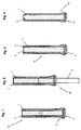
- Fig. 1 shows in a longitudinal section schematically a step of a manufacturing method according to the invention for composite pipes 10.
- a first tube 1 is produced by means of formwork technology.
- the first tube 1 is designed as a fresh concrete pipe. This fresh concrete is poured into a formwork with an inner formwork and an outer formwork.
- An inner formwork (core) is shown in the illustration Fig. 1 already removed.
- the outer casing 2 (outer casing) is still on the first pipe 1.
- a broadening of the outer dimension is present. Accordingly, the wall thickness is formed stronger in this region of the lower end 3, so that a steel lower sleeve 4 can be arranged there.
- This steel lower sleeve 4 supports the formwork technique and the lower end 3 is due to the special shape suitable for connection to other composite pipes 10.
- the first tube 1 is not yet cured; the concrete is still earth-moist and thus plastically deformable.
- Fig. 2 shows in a longitudinal section schematically a step according to Fig. 1 following step of the manufacturing method according to the invention.
- a second tube 5 is pressed from below through the steel lower sleeve 4 into the not yet cured first tube 1.
- the second tube 5 is a liner tube, which is preferably made of a corrosion-resistant plastic.
- the outer shape and the outer dimensions of the second tube 5 correspond essentially to the inner shape and the inner dimensions of the first tube 1, ie within a tolerance range, the corresponding shapes and / or dimensions of the tubes 1, 5 correspond.
- the second tube 5 When pressed in, the second tube 5 slides in the first tube 1, which is supported by the moist and deformable state of the first tube 1.
- the outer formwork 2 is still present and prevents the first pipe 1 from being pressed apart.
- the second pipe 5 In the illustrated state, the second pipe 5 is pressed into the first pipe 1 by about one third.
- Fig. 3 shows in a longitudinal section schematically a step according to Fig. 2 following step of the manufacturing method according to the invention.
- the second tube 5 is completely pressed into the first tube 1.
- the first tube 1 has not yet fully cured.
- the outer formwork 2 is still outside on the first tube. 1
- Fig. 4 shows in a longitudinal section schematically a step according to Fig. 3 following step of the manufacturing method according to the invention.
- the outer formwork 2 is now removed from the first tube 1.
- the second tube 5 is located in the first tube 1.
- the outer first tube 1 can now fully cure in this state. It is shrunk by the hydraulic setting process on the second tube 5, so that a permanent non-positive and stable connection between the first tube 1 and the second tube 5 is formed.
- the composite pipe 10 is thus completed. After removal of the steel lower sleeve 4, the composite pipes 10 produced in this way can be joined into a tube composite.
- Fig. 5 shows in a sectional view another embodiment of a composite tube 10 in a horizontal position.
- the composite tube 10 comprises a first outer tube 1 and a second inner tube 5.
- the latter is in the present case designed as a plastic plastic liner such as PVC, PP or PE.
- the first pipe 1 is a concrete pipe, more precisely a void-free SV concrete pipe, with an integrated longitudinal reinforcement 6, preferably of steel, which extends along a pipe longitudinal direction L.
- the composite tube 10 comprises on an outer surface of the outer tube 1 a pressure pad 7, which is integrally attached to the tube 1 and provides a point of application for handling the composite tube 10.
- a ball head anchor 8 is arranged. This also serves to facilitate handling, in particular laying, the composite pipes 10th
- a chip 9 is provided in the composite tube 10. This can be integrated in the first outer tube 1 or in the second inner tube 5. Data can be stored on the chip 9 via the composite tube 10. These data may include: date, location, manufacturer, piping, dimensions or material. These data can be read out of the chip 9 via suitable readers and further processed.
- the composite pipe 10 is opened at both ends.
- the lower end 3 in this case has a sleeve 4, which is designed to receive a correspondingly formed upper end 11 1 of a composite pipe 10 to be joined.
- the sleeve 4 at the lower end 3 is approximately double-ring-shaped with a first ring portion 4a in the outer concrete pipe 1 and a second ring portion 4b in the liner 5. It can be seen that Furthermore, the inner diameter of the second annular section 4b is greater than the inner diameter of the liner tube 5, so that towards the end of each step is formed.
- the outer tube 1 forms within the sleeve 4 a stop 12, which limits the reception of a second composite tube 10.
- the male in a sleeve 4 upper end 11 of the composite tube 10 has on the outer tube 1 a tapered shoulder 13 which is received by the first ring portion 4 a of the sleeve 4.
- the inner tube 5 has exactly as at the lower end 3, a ring portion 13 a, which has a slightly larger inner diameter than the liner tube 5, so that here too a step is formed towards the end.
- the inner diameter of the ring sections 4b and 13a are the same size.
- the first tube When joining two composite tubes 10, the first tube is inserted with its shoulder 13 in the sleeve 4 of the other tube, the shoulder 13 comes to rest on the ring stop 12.
- a (not shown) rubber seal seals the concrete pipes 1 against each other. It is preferably located between the first ring portion 4 a of the sleeve 4 and the shoulder 13.
- the lying with their front edges inline tubes 5 are sealed by a (not shown) ring sleeve, which is preferably made of the same material as the liner tubes 5. It is used in joining the composite tubes 10 in the ring sections 4b, 13a of the ends 3, 11 and sealed in it, eg by means of an elastomeric seal, by gluing, by friction or by welding.
- the wall thickness of the annular sleeve corresponds to the height of the step between the inner diameter of the ring sections 4b, 13a and the inner diameter of the inliner tubes 5.
- the inner diameter of the annular sleeve corresponds to the inner diameter of the inliner tubes 5, so that they form a pipeline with a continuously constant inner diameter.
- Each ring portion 4b, 13a may be provided with an annular groove 14, in which an additional rubber seal is inserted. In this way, the composite tubes 10 are always permanently sealed together. The guided in the tubes 10 medium can not escape to the outside.
- Fig. 6 shows a cross section through the composite pipe according to Fig. 5 along the line 1-1.
- the composite tube 10 after Fig. 6 has an annular cross-section.
- the outer tube 1 of the ball anchor 8 is integrated approximately in 12 o'clock position.
- one ballast marker 16 each is in the form of a projection educated. Based on this bedding marking 16, an optimal bedding of the composite tube 10 can be realized.
- the circular plastic liner tube 5 is shown.
- the composite tube comprises a first tube and a second tube attached thereto.
- the attachment is carried out according to the inventive method.
- the second tube is attached to the not yet cured first tube by means of suitable methods. Thereafter, the first tube hardens completely.
- first tube is an outer tube and the second tube is an inner tube, which via a non-positive connection, such as by shrinking, press fitting and the like.
- a non-positive connection such as by shrinking, press fitting and the like.
- the composite pipe is formed so that the first pipe is made of a material comprising concrete, reinforced concrete, reinforced concrete, concrete mixes and the like.
- the second tube is preferably made of plastic and is more preferably a liner tube, that is a coating of plastic, preferably in the form of a prefabricated tube.
- the tubes may have any cross-sectional shape.
- a triangular, square, polygonal, circular, elliptical, egg-shaped or other cross-section may be provided.
- the inner dimensions of the first tube essentially correspond to the outer dimensions of the second tube.
- the cross sections are formed correspondingly corresponding, that is, the cross section of the outer tube is circular, so the adjacent part of the inner tube is complementary, that is also circular. More precisely, the adjacent contours of the outer tube and the inner tube correspond.
- the composite tube has at least one sleeve at the end.
- the composite pipe has a at each end Sleeve on.
- the sleeves are adapted to the inner contour of the corresponding end of the tube.
- the sleeves continue each other, that is, they form a fluid channel in a juxtaposition.
Landscapes
- Engineering & Computer Science (AREA)
- Mechanical Engineering (AREA)
- General Engineering & Computer Science (AREA)
- Manufacturing & Machinery (AREA)
- Chemical & Material Sciences (AREA)
- Ceramic Engineering (AREA)
- Structural Engineering (AREA)
- Rigid Pipes And Flexible Pipes (AREA)
- Manufacturing Of Tubular Articles Or Embedded Moulded Articles (AREA)
Claims (5)
- Procédé de fabrication de tubes composites (10), en particulier de tubes de gainage composites composés d'un premier tube (1) en béton et d'un deuxième tube (5) en matériau résistant à la corrosion, comprenant les étapes suivantes :fabrication du premier tube (1) dans le mode de fabrication en coffrage avec une coque extérieure (2) et une coque intérieure,mise en place du deuxième tube (5) sur le premier tube (1),caractérisé en ce quea) le deuxième tube (5) est mis en place sur le premier tube (1) non encore durci, la mise en place du deuxième tube (5) sur le premier tube (1) comprenant l'étape suivante :enlèvement au moins partiel d'un des coffrages du premier tube (1) de telle sorte que le premier tube (1) présente une partie au moins partiellement dépourvue de coffrage sur laquelle le deuxième tube (5) est mis en place ; en ce queb) le premier tube (1) est un tube extérieur et le deuxième tube (5) est un tube intérieur,c) le deuxième tube (5), après l'enlèvement du coffrage intérieur, étant inséré dans le premier tube (1) non encore durci, etd) à l'intérieur d'une plage de tolérance qui se situe de préférence dans une plage d'environ -15 % à +15 % de différence, de façon plus préférée d'environ -10 % à +10 % de différence, et de façon la plus préférée d'environ - 5 % à +5 % de différence, les dimensions extérieures du deuxième tube (5) correspondant aux dimensions intérieures correspondantes du premier tube (1) ; et en ce quee) le premier tube (1) est réalisé dans un matériau qui, lors du durcissement, modifie son volume et/ou sa forme en direction du deuxième tube (5),f) la plage de tolérance étant dimensionnée de telle sorte que, après le durcissement du béton, il apparaît un raccordement par liaison de force entre le premier tube (1) et le deuxième tube (5).
- Procédé selon la revendication 1, caractérisé en ce que, après la mise en place du deuxième tube (5), le coffrage (2) restant est enlevé.
- Procédé selon une des revendications précédentes 1 à 2, caractérisé en ce que le matériau pour le premier tube (1) est sélectionné parmi un groupe de matériaux qui présentent un retrait lors du durcissement.
- Procédé selon la revendication 3, caractérisé en ce que le matériau pour le premier tube (1) est du béton ou un mélange de béton.
- Procédé selon une des revendications 1 à 4, caractérisé en ce que le matériau pour le deuxième tube (5) est sélectionné parmi un groupe de matériaux appropriés comprenant : matière plastique, grès, matières plastiques renforcées de fibre de verre, verre et similaires.
Applications Claiming Priority (1)
| Application Number | Priority Date | Filing Date | Title |
|---|---|---|---|
| DE200710058885 DE102007058885A1 (de) | 2007-12-05 | 2007-12-05 | Verbundrohr und Verfahren zu dessen Herstellung |
Publications (3)
| Publication Number | Publication Date |
|---|---|
| EP2067590A2 EP2067590A2 (fr) | 2009-06-10 |
| EP2067590A3 EP2067590A3 (fr) | 2011-03-23 |
| EP2067590B1 true EP2067590B1 (fr) | 2013-09-11 |
Family
ID=40451429
Family Applications (1)
| Application Number | Title | Priority Date | Filing Date |
|---|---|---|---|
| EP20080021158 Active EP2067590B1 (fr) | 2007-12-05 | 2008-12-05 | Procédé de fabrication de tuyaux composites |
Country Status (4)
| Country | Link |
|---|---|
| EP (1) | EP2067590B1 (fr) |
| DE (1) | DE102007058885A1 (fr) |
| DK (1) | DK2067590T3 (fr) |
| ES (1) | ES2438769T3 (fr) |
Cited By (2)
| Publication number | Priority date | Publication date | Assignee | Title |
|---|---|---|---|---|
| DE102018101178A1 (de) | 2018-01-19 | 2019-07-25 | J.H. & Wilhelm Finger Gmbh & Co Kg | Betonrohr mit einem einer Innenauskleidung bildenden Kunststoffrohr |
| CN110774411A (zh) * | 2019-10-31 | 2020-02-11 | 杜永明 | 一种陶瓷内衬复合管的制备方法 |
Families Citing this family (5)
| Publication number | Priority date | Publication date | Assignee | Title |
|---|---|---|---|---|
| CN101776187B (zh) * | 2010-02-26 | 2012-04-04 | 武汉理工大学 | 预应力混凝土玻璃钢复合管材结构及其制作工艺 |
| CN102588684B (zh) * | 2011-01-11 | 2015-11-25 | 深圳市吉凌复合材料科技股份有限公司 | 一种新型纤维增强塑料混凝土复合管 |
| CN102269299B (zh) * | 2011-08-01 | 2012-12-19 | 娄底市朝阳塑胶有限公司 | 一种具有加强筋的塑、砼、纤维复合管 |
| DE102014211030A1 (de) | 2014-06-10 | 2015-12-17 | Bfs Betonfertigteilesysteme Gmbh | Verfahren und Vorrichtung zur Herstellung eines Kanalrohrelements |
| CN108889859B (zh) * | 2018-08-22 | 2024-03-12 | 江苏众信绿色管业科技有限公司 | 一种钢衬不锈钢内螺纹管件复合加工设备 |
Family Cites Families (10)
| Publication number | Priority date | Publication date | Assignee | Title |
|---|---|---|---|---|
| DE1762990U (de) * | 1957-12-31 | 1958-03-06 | Buderus Eisenwerk | Betonrohr. |
| DE7534245U (de) | 1975-10-28 | 1976-04-22 | Gekaton Abwasserrohre Gmbh & Co Kg, 8433 Parsberg | Korrosionsschutzrohr |
| DE2634992A1 (de) | 1976-08-04 | 1978-02-09 | Arikan Geb Kartan Sevinc Dipl | Schutzhuelle und verfahren zu deren nachtraeglichen anbringen an den innenwandungsflaechen oder teilen dieser von waagerechten oder senkrechten rohrfoermigen oder kanalartigen bauwerken, insbesondere betonrohren, zum zwecke der abdichtung und/oder ausbildung eines innenflaechenschutzes |
| DE7815282U1 (de) | 1978-05-20 | 1978-08-31 | Dyckerhoff & Widmann Ag, 8000 Muenchen | Betonrohr mit korrosionsbestaendiger auskleidung |
| DE2852007A1 (de) * | 1978-12-01 | 1980-08-07 | Hacheney Wilfried | Verfahren zur herstellung von spannbeton-rohren sowie nach diesem verfahren hergestelltes rohr |
| DE3815843C3 (de) * | 1988-05-09 | 1998-01-29 | Fasel Geb Willwacher Ulrike | Rohre und dgl. Formteile aus Beton mit einer korrosionsfesten Innenauskleidung und mit einem zum Teil flexiblen Verbund |
| DE4127992A1 (de) * | 1991-08-23 | 1993-02-25 | Huels Troisdorf | Beton-kunststoff-verbundrohr, verfahren zu seiner herstellung und seine verwendung als vortriebsrohr |
| DE29700398U1 (de) * | 1997-01-11 | 1997-03-13 | REHAU AG + Co., 95111 Rehau | Betonrohr mit Innenauskleidung aus Kunststoff |
| DE19745599C2 (de) | 1997-10-07 | 2001-05-17 | Hupfeld Beton Gmbh & Co | Verbundrohr und Verfahren zu dessen Herstellung |
| DE19855572C2 (de) | 1998-12-02 | 2002-11-28 | Zueblin Ag | Verfahren zur Betonrohrfertigung mit Inliner und bewegliche Innenschalung für dieses Verfahren |
-
2007
- 2007-12-05 DE DE200710058885 patent/DE102007058885A1/de not_active Withdrawn
-
2008
- 2008-12-05 DK DK08021158T patent/DK2067590T3/da active
- 2008-12-05 ES ES08021158T patent/ES2438769T3/es active Active
- 2008-12-05 EP EP20080021158 patent/EP2067590B1/fr active Active
Cited By (2)
| Publication number | Priority date | Publication date | Assignee | Title |
|---|---|---|---|---|
| DE102018101178A1 (de) | 2018-01-19 | 2019-07-25 | J.H. & Wilhelm Finger Gmbh & Co Kg | Betonrohr mit einem einer Innenauskleidung bildenden Kunststoffrohr |
| CN110774411A (zh) * | 2019-10-31 | 2020-02-11 | 杜永明 | 一种陶瓷内衬复合管的制备方法 |
Also Published As
| Publication number | Publication date |
|---|---|
| DE102007058885A1 (de) | 2009-06-10 |
| EP2067590A2 (fr) | 2009-06-10 |
| ES2438769T3 (es) | 2014-01-20 |
| EP2067590A3 (fr) | 2011-03-23 |
| DK2067590T3 (da) | 2013-12-16 |
Similar Documents
| Publication | Publication Date | Title |
|---|---|---|
| EP1929109B1 (fr) | Concept de tour | |
| EP2067590A2 (fr) | Tuyau composite et son procédé de fabrication | |
| EP2369130B1 (fr) | Procédé d'assainissement d'une galerie | |
| EP3154757B1 (fr) | Procédé et dispositif de fabrication d'un élément de tube de canal | |
| EP3812523B1 (fr) | Revêtement de fond de puits | |
| WO2014037113A1 (fr) | Ensemble d'ancrage haute résistance d'un élément de précontrainte dans une pièce, l'élément de précontrainte comportant une tige de précontrainte, et procédé de production dudit ancrage | |
| DE102007015270A1 (de) | Verfahren zur Herstellung eines Schachtunterteils | |
| DE3503799A1 (de) | Verfahren zum sanieren von beschaedigten abschnitten eines im erdreich verlegten kanals | |
| DE3302075C2 (de) | Verbindung für Spannbeton- oder Stahlbetonbiegeträger | |
| DE102013109594A1 (de) | Tübbing mit einer gegossenen Schutzschicht sowie Verfahren zur Herstellung eines derartigen Tübbings | |
| DE102008064141A1 (de) | Asphaltierte Verkehrsfläche | |
| DE10345124B4 (de) | Vorrichtung zur Auskleidung eines Kanals | |
| EP1647640B1 (fr) | Tuyau de canalisation, notamment tuyau de fonçage, et son procédé de fabrication | |
| DE10315560B3 (de) | Verfahren zur Sanierung eines Abwasserschachtes und Verwendung eines zugehörigen Rohres | |
| DE102009033834B3 (de) | Hubvorrichtung für Bodenplatten | |
| AT393147B (de) | Vorgefertigtes schachtbodenelement, insbesondere fuer kanalschaechte, sowie verfahren und vorrichtungzur herstellung eines solchen schachtbodenelementes | |
| DE10053008B4 (de) | Verfahren und Vorrichtung zur Herstellung stahlbetonummantelter Vortriebsrohre | |
| EP0759488A1 (fr) | Elément de construction pour puits | |
| DD281848A5 (de) | Verfahren zur reparatur von baukonstruktionen | |
| DE202004011702U1 (de) | Infrastruktur-Kanal | |
| EP1167644A2 (fr) | Support et procédé de fabrication de canalisations, en particulier de canalisations d'eau, avec utilisation de manchons tubulaires | |
| DE10103731C1 (de) | Rohranschlusssystem für einen Betonschacht | |
| DE102015110887A1 (de) | Vorrichtung und Verfahren zum Anheben einer Schachtabdeckung insbesondere Kanaldeckel | |
| DE202023103550U1 (de) | Bausatz zur Rohrsanierung | |
| DE4011736A1 (de) | Verfahren zur herstellung von schaechten |
Legal Events
| Date | Code | Title | Description |
|---|---|---|---|
| PUAI | Public reference made under article 153(3) epc to a published international application that has entered the european phase |
Free format text: ORIGINAL CODE: 0009012 |
|
| AK | Designated contracting states |
Kind code of ref document: A2 Designated state(s): AT BE BG CH CY CZ DE DK EE ES FI FR GB GR HR HU IE IS IT LI LT LU LV MC MT NL NO PL PT RO SE SI SK TR |
|
| AX | Request for extension of the european patent |
Extension state: AL BA MK RS |
|
| PUAL | Search report despatched |
Free format text: ORIGINAL CODE: 0009013 |
|
| AK | Designated contracting states |
Kind code of ref document: A3 Designated state(s): AT BE BG CH CY CZ DE DK EE ES FI FR GB GR HR HU IE IS IT LI LT LU LV MC MT NL NO PL PT RO SE SI SK TR |
|
| AX | Request for extension of the european patent |
Extension state: AL BA MK RS |
|
| RIC1 | Information provided on ipc code assigned before grant |
Ipc: B28B 21/72 20060101AFI20090325BHEP Ipc: B28B 21/92 20060101ALI20110217BHEP Ipc: F16L 9/08 20060101ALI20110217BHEP Ipc: B32B 13/12 20060101ALI20110217BHEP Ipc: F16L 9/14 20060101ALI20110217BHEP Ipc: B28B 21/58 20060101ALI20110217BHEP |
|
| 17P | Request for examination filed |
Effective date: 20110601 |
|
| AKX | Designation fees paid |
Designated state(s): AT BE BG CH CY CZ DE DK EE ES FI FR GB GR HR HU IE IS IT LI LT LU LV MC MT NL NO PL PT RO SE SI SK TR |
|
| 17Q | First examination report despatched |
Effective date: 20111104 |
|
| GRAP | Despatch of communication of intention to grant a patent |
Free format text: ORIGINAL CODE: EPIDOSNIGR1 |
|
| INTG | Intention to grant announced |
Effective date: 20130405 |
|
| GRAS | Grant fee paid |
Free format text: ORIGINAL CODE: EPIDOSNIGR3 |
|
| GRAA | (expected) grant |
Free format text: ORIGINAL CODE: 0009210 |
|
| AK | Designated contracting states |
Kind code of ref document: B1 Designated state(s): AT BE BG CH CY CZ DE DK EE ES FI FR GB GR HR HU IE IS IT LI LT LU LV MC MT NL NO PL PT RO SE SI SK TR |
|
| REG | Reference to a national code |
Ref country code: GB Ref legal event code: FG4D Free format text: NOT ENGLISH |
|
| REG | Reference to a national code |
Ref country code: CH Ref legal event code: EP |
|
| REG | Reference to a national code |
Ref country code: AT Ref legal event code: REF Ref document number: 631355 Country of ref document: AT Kind code of ref document: T Effective date: 20130915 |
|
| REG | Reference to a national code |
Ref country code: IE Ref legal event code: FG4D Free format text: LANGUAGE OF EP DOCUMENT: GERMAN |
|
| REG | Reference to a national code |
Ref country code: DE Ref legal event code: R096 Ref document number: 502008010634 Country of ref document: DE Effective date: 20131107 |
|
| REG | Reference to a national code |
Ref country code: DK Ref legal event code: T3 Effective date: 20131212 |
|
| REG | Reference to a national code |
Ref country code: ES Ref legal event code: FG2A Ref document number: 2438769 Country of ref document: ES Kind code of ref document: T3 Effective date: 20140120 |
|
| PG25 | Lapsed in a contracting state [announced via postgrant information from national office to epo] |
Ref country code: CY Free format text: LAPSE BECAUSE OF FAILURE TO SUBMIT A TRANSLATION OF THE DESCRIPTION OR TO PAY THE FEE WITHIN THE PRESCRIBED TIME-LIMIT Effective date: 20130731 Ref country code: LT Free format text: LAPSE BECAUSE OF FAILURE TO SUBMIT A TRANSLATION OF THE DESCRIPTION OR TO PAY THE FEE WITHIN THE PRESCRIBED TIME-LIMIT Effective date: 20130911 Ref country code: SE Free format text: LAPSE BECAUSE OF FAILURE TO SUBMIT A TRANSLATION OF THE DESCRIPTION OR TO PAY THE FEE WITHIN THE PRESCRIBED TIME-LIMIT Effective date: 20130911 Ref country code: HR Free format text: LAPSE BECAUSE OF FAILURE TO SUBMIT A TRANSLATION OF THE DESCRIPTION OR TO PAY THE FEE WITHIN THE PRESCRIBED TIME-LIMIT Effective date: 20130911 Ref country code: NO Free format text: LAPSE BECAUSE OF FAILURE TO SUBMIT A TRANSLATION OF THE DESCRIPTION OR TO PAY THE FEE WITHIN THE PRESCRIBED TIME-LIMIT Effective date: 20131211 |
|
| REG | Reference to a national code |
Ref country code: NL Ref legal event code: VDEP Effective date: 20130911 |
|
| REG | Reference to a national code |
Ref country code: LT Ref legal event code: MG4D |
|
| PG25 | Lapsed in a contracting state [announced via postgrant information from national office to epo] |
Ref country code: GR Free format text: LAPSE BECAUSE OF FAILURE TO SUBMIT A TRANSLATION OF THE DESCRIPTION OR TO PAY THE FEE WITHIN THE PRESCRIBED TIME-LIMIT Effective date: 20131212 Ref country code: FI Free format text: LAPSE BECAUSE OF FAILURE TO SUBMIT A TRANSLATION OF THE DESCRIPTION OR TO PAY THE FEE WITHIN THE PRESCRIBED TIME-LIMIT Effective date: 20130911 Ref country code: SI Free format text: LAPSE BECAUSE OF FAILURE TO SUBMIT A TRANSLATION OF THE DESCRIPTION OR TO PAY THE FEE WITHIN THE PRESCRIBED TIME-LIMIT Effective date: 20130911 Ref country code: LV Free format text: LAPSE BECAUSE OF FAILURE TO SUBMIT A TRANSLATION OF THE DESCRIPTION OR TO PAY THE FEE WITHIN THE PRESCRIBED TIME-LIMIT Effective date: 20130911 |
|
| PG25 | Lapsed in a contracting state [announced via postgrant information from national office to epo] |
Ref country code: CY Free format text: LAPSE BECAUSE OF FAILURE TO SUBMIT A TRANSLATION OF THE DESCRIPTION OR TO PAY THE FEE WITHIN THE PRESCRIBED TIME-LIMIT Effective date: 20130911 |
|
| REG | Reference to a national code |
Ref country code: SK Ref legal event code: T3 Ref document number: E 15524 Country of ref document: SK |
|
| PG25 | Lapsed in a contracting state [announced via postgrant information from national office to epo] |
Ref country code: IS Free format text: LAPSE BECAUSE OF FAILURE TO SUBMIT A TRANSLATION OF THE DESCRIPTION OR TO PAY THE FEE WITHIN THE PRESCRIBED TIME-LIMIT Effective date: 20140111 Ref country code: NL Free format text: LAPSE BECAUSE OF FAILURE TO SUBMIT A TRANSLATION OF THE DESCRIPTION OR TO PAY THE FEE WITHIN THE PRESCRIBED TIME-LIMIT Effective date: 20130911 Ref country code: RO Free format text: LAPSE BECAUSE OF FAILURE TO SUBMIT A TRANSLATION OF THE DESCRIPTION OR TO PAY THE FEE WITHIN THE PRESCRIBED TIME-LIMIT Effective date: 20130911 Ref country code: EE Free format text: LAPSE BECAUSE OF FAILURE TO SUBMIT A TRANSLATION OF THE DESCRIPTION OR TO PAY THE FEE WITHIN THE PRESCRIBED TIME-LIMIT Effective date: 20130911 |
|
| PG25 | Lapsed in a contracting state [announced via postgrant information from national office to epo] |
Ref country code: PL Free format text: LAPSE BECAUSE OF FAILURE TO SUBMIT A TRANSLATION OF THE DESCRIPTION OR TO PAY THE FEE WITHIN THE PRESCRIBED TIME-LIMIT Effective date: 20130911 |
|
| REG | Reference to a national code |
Ref country code: DE Ref legal event code: R097 Ref document number: 502008010634 Country of ref document: DE |
|
| PG25 | Lapsed in a contracting state [announced via postgrant information from national office to epo] |
Ref country code: PT Free format text: LAPSE BECAUSE OF FAILURE TO SUBMIT A TRANSLATION OF THE DESCRIPTION OR TO PAY THE FEE WITHIN THE PRESCRIBED TIME-LIMIT Effective date: 20140113 |
|
| PLBE | No opposition filed within time limit |
Free format text: ORIGINAL CODE: 0009261 |
|
| STAA | Information on the status of an ep patent application or granted ep patent |
Free format text: STATUS: NO OPPOSITION FILED WITHIN TIME LIMIT |
|
| 26N | No opposition filed |
Effective date: 20140612 |
|
| GBPC | Gb: european patent ceased through non-payment of renewal fee |
Effective date: 20131211 |
|
| PG25 | Lapsed in a contracting state [announced via postgrant information from national office to epo] |
Ref country code: MC Free format text: LAPSE BECAUSE OF FAILURE TO SUBMIT A TRANSLATION OF THE DESCRIPTION OR TO PAY THE FEE WITHIN THE PRESCRIBED TIME-LIMIT Effective date: 20130911 |
|
| REG | Reference to a national code |
Ref country code: IE Ref legal event code: MM4A |
|
| REG | Reference to a national code |
Ref country code: DE Ref legal event code: R097 Ref document number: 502008010634 Country of ref document: DE Effective date: 20140612 |
|
| PG25 | Lapsed in a contracting state [announced via postgrant information from national office to epo] |
Ref country code: IE Free format text: LAPSE BECAUSE OF NON-PAYMENT OF DUE FEES Effective date: 20131205 |
|
| PG25 | Lapsed in a contracting state [announced via postgrant information from national office to epo] |
Ref country code: GB Free format text: LAPSE BECAUSE OF NON-PAYMENT OF DUE FEES Effective date: 20131211 |
|
| PG25 | Lapsed in a contracting state [announced via postgrant information from national office to epo] |
Ref country code: TR Free format text: LAPSE BECAUSE OF FAILURE TO SUBMIT A TRANSLATION OF THE DESCRIPTION OR TO PAY THE FEE WITHIN THE PRESCRIBED TIME-LIMIT Effective date: 20130911 |
|
| PG25 | Lapsed in a contracting state [announced via postgrant information from national office to epo] |
Ref country code: HU Free format text: LAPSE BECAUSE OF FAILURE TO SUBMIT A TRANSLATION OF THE DESCRIPTION OR TO PAY THE FEE WITHIN THE PRESCRIBED TIME-LIMIT; INVALID AB INITIO Effective date: 20081205 Ref country code: BG Free format text: LAPSE BECAUSE OF FAILURE TO SUBMIT A TRANSLATION OF THE DESCRIPTION OR TO PAY THE FEE WITHIN THE PRESCRIBED TIME-LIMIT Effective date: 20130911 |
|
| PG25 | Lapsed in a contracting state [announced via postgrant information from national office to epo] |
Ref country code: MT Free format text: LAPSE BECAUSE OF FAILURE TO SUBMIT A TRANSLATION OF THE DESCRIPTION OR TO PAY THE FEE WITHIN THE PRESCRIBED TIME-LIMIT Effective date: 20130911 |
|
| REG | Reference to a national code |
Ref country code: FR Ref legal event code: PLFP Year of fee payment: 8 |
|
| PGFP | Annual fee paid to national office [announced via postgrant information from national office to epo] |
Ref country code: CZ Payment date: 20151204 Year of fee payment: 8 Ref country code: SK Payment date: 20151204 Year of fee payment: 8 |
|
| REG | Reference to a national code |
Ref country code: FR Ref legal event code: PLFP Year of fee payment: 9 |
|
| REG | Reference to a national code |
Ref country code: DE Ref legal event code: R082 Ref document number: 502008010634 Country of ref document: DE Representative=s name: PATENTANWAELTE OLBRICHT, BUCHHOLD, KEULERTZ PA, DE |
|
| PG25 | Lapsed in a contracting state [announced via postgrant information from national office to epo] |
Ref country code: CZ Free format text: LAPSE BECAUSE OF NON-PAYMENT OF DUE FEES Effective date: 20161205 |
|
| REG | Reference to a national code |
Ref country code: SK Ref legal event code: MM4A Ref document number: E 15524 Country of ref document: SK Effective date: 20161205 |
|
| PG25 | Lapsed in a contracting state [announced via postgrant information from national office to epo] |
Ref country code: SK Free format text: LAPSE BECAUSE OF NON-PAYMENT OF DUE FEES Effective date: 20161205 |
|
| REG | Reference to a national code |
Ref country code: FR Ref legal event code: PLFP Year of fee payment: 10 |
|
| PGFP | Annual fee paid to national office [announced via postgrant information from national office to epo] |
Ref country code: DK Payment date: 20181221 Year of fee payment: 11 Ref country code: AT Payment date: 20181220 Year of fee payment: 11 |
|
| PGFP | Annual fee paid to national office [announced via postgrant information from national office to epo] |
Ref country code: IT Payment date: 20181220 Year of fee payment: 11 |
|
| REG | Reference to a national code |
Ref country code: DK Ref legal event code: EBP Effective date: 20191231 |
|
| REG | Reference to a national code |
Ref country code: CH Ref legal event code: PL |
|
| REG | Reference to a national code |
Ref country code: AT Ref legal event code: MM01 Ref document number: 631355 Country of ref document: AT Kind code of ref document: T Effective date: 20191205 |
|
| PG25 | Lapsed in a contracting state [announced via postgrant information from national office to epo] |
Ref country code: IT Free format text: LAPSE BECAUSE OF NON-PAYMENT OF DUE FEES Effective date: 20191205 |
|
| PG25 | Lapsed in a contracting state [announced via postgrant information from national office to epo] |
Ref country code: AT Free format text: LAPSE BECAUSE OF NON-PAYMENT OF DUE FEES Effective date: 20191205 Ref country code: LI Free format text: LAPSE BECAUSE OF NON-PAYMENT OF DUE FEES Effective date: 20191231 Ref country code: CH Free format text: LAPSE BECAUSE OF NON-PAYMENT OF DUE FEES Effective date: 20191231 |
|
| PG25 | Lapsed in a contracting state [announced via postgrant information from national office to epo] |
Ref country code: DK Free format text: LAPSE BECAUSE OF NON-PAYMENT OF DUE FEES Effective date: 20191231 |
|
| PGFP | Annual fee paid to national office [announced via postgrant information from national office to epo] |
Ref country code: LU Payment date: 20211222 Year of fee payment: 14 |
|
| PG25 | Lapsed in a contracting state [announced via postgrant information from national office to epo] |
Ref country code: LU Free format text: LAPSE BECAUSE OF NON-PAYMENT OF DUE FEES Effective date: 20221205 |
|
| PGFP | Annual fee paid to national office [announced via postgrant information from national office to epo] |
Ref country code: FR Payment date: 20251222 Year of fee payment: 18 |
|
| PGFP | Annual fee paid to national office [announced via postgrant information from national office to epo] |
Ref country code: BE Payment date: 20251219 Year of fee payment: 18 |
|
| PGFP | Annual fee paid to national office [announced via postgrant information from national office to epo] |
Ref country code: ES Payment date: 20260130 Year of fee payment: 18 |
|
| PGFP | Annual fee paid to national office [announced via postgrant information from national office to epo] |
Ref country code: DE Payment date: 20251231 Year of fee payment: 18 |