EP2067610B1 - Appareil de formation optique et procédé de formation optique - Google Patents
Appareil de formation optique et procédé de formation optique Download PDFInfo
- Publication number
- EP2067610B1 EP2067610B1 EP08020458A EP08020458A EP2067610B1 EP 2067610 B1 EP2067610 B1 EP 2067610B1 EP 08020458 A EP08020458 A EP 08020458A EP 08020458 A EP08020458 A EP 08020458A EP 2067610 B1 EP2067610 B1 EP 2067610B1
- Authority
- EP
- European Patent Office
- Prior art keywords
- work small
- work
- small area
- areas
- data
- Prior art date
- Legal status (The legal status is an assumption and is not a legal conclusion. Google has not performed a legal analysis and makes no representation as to the accuracy of the status listed.)
- Not-in-force
Links
Images




Classifications
-
- B—PERFORMING OPERATIONS; TRANSPORTING
- B29—WORKING OF PLASTICS; WORKING OF SUBSTANCES IN A PLASTIC STATE IN GENERAL
- B29C—SHAPING OR JOINING OF PLASTICS; SHAPING OF MATERIAL IN A PLASTIC STATE, NOT OTHERWISE PROVIDED FOR; AFTER-TREATMENT OF THE SHAPED PRODUCTS, e.g. REPAIRING
- B29C64/00—Additive manufacturing, i.e. manufacturing of three-dimensional [3D] objects by additive deposition, additive agglomeration or additive layering, e.g. by 3D printing, stereolithography or selective laser sintering
- B29C64/10—Processes of additive manufacturing
- B29C64/106—Processes of additive manufacturing using only liquids or viscous materials, e.g. depositing a continuous bead of viscous material
- B29C64/124—Processes of additive manufacturing using only liquids or viscous materials, e.g. depositing a continuous bead of viscous material using layers of liquid which are selectively solidified
- B29C64/129—Processes of additive manufacturing using only liquids or viscous materials, e.g. depositing a continuous bead of viscous material using layers of liquid which are selectively solidified characterised by the energy source therefor, e.g. by global irradiation combined with a mask
- B29C64/135—Processes of additive manufacturing using only liquids or viscous materials, e.g. depositing a continuous bead of viscous material using layers of liquid which are selectively solidified characterised by the energy source therefor, e.g. by global irradiation combined with a mask the energy source being concentrated, e.g. scanning lasers or focused light sources
-
- B—PERFORMING OPERATIONS; TRANSPORTING
- B33—ADDITIVE MANUFACTURING TECHNOLOGY
- B33Y—ADDITIVE MANUFACTURING, i.e. MANUFACTURING OF THREE-DIMENSIONAL [3D] OBJECTS BY ADDITIVE DEPOSITION, ADDITIVE AGGLOMERATION OR ADDITIVE LAYERING, e.g. BY 3D PRINTING, STEREOLITHOGRAPHY OR SELECTIVE LASER SINTERING
- B33Y50/00—Data acquisition or data processing for additive manufacturing
-
- B—PERFORMING OPERATIONS; TRANSPORTING
- B29—WORKING OF PLASTICS; WORKING OF SUBSTANCES IN A PLASTIC STATE IN GENERAL
- B29C—SHAPING OR JOINING OF PLASTICS; SHAPING OF MATERIAL IN A PLASTIC STATE, NOT OTHERWISE PROVIDED FOR; AFTER-TREATMENT OF THE SHAPED PRODUCTS, e.g. REPAIRING
- B29C64/00—Additive manufacturing, i.e. manufacturing of three-dimensional [3D] objects by additive deposition, additive agglomeration or additive layering, e.g. by 3D printing, stereolithography or selective laser sintering
- B29C64/10—Processes of additive manufacturing
- B29C64/106—Processes of additive manufacturing using only liquids or viscous materials, e.g. depositing a continuous bead of viscous material
- B29C64/124—Processes of additive manufacturing using only liquids or viscous materials, e.g. depositing a continuous bead of viscous material using layers of liquid which are selectively solidified
Definitions
- the present invention contains subject matter related to Japanese Patent Application JP 2007-312027 filed in the Japanese Patent Office on December 3, 2007, the entire contents of which are incorporated herein by reference.
- the present invention relates to an optical shaping apparatus and optical shaping method, and particularly, relates to an optical shaping apparatus and optical shaping method whereby a high-precision shaped object can be shaped with high strength.
- CAD Computer Aided Design
- machining device or the like which is numerically-controlled is employed to create a three-dimensional model by machining.
- RP rapid prototyping
- a manufacturing technique called a layering shaping method is employed wherein cross-sectional shaped thin plates are created by a three-dimensional model being sliced based on the three-dimensional shape data of the three-dimensional model, and the cross-sectional shaped thin plates thereof are layered, thereby creating a three-dimensional model.
- rapid prototyping is classified into optical shaping employing an ultraviolet hardening resin, a method for extrusion-layering thermoplastic resins (FDM), a powder melt adhesion layering method (SLS), a paper thin-film layering method (LOM), a method for discharge-layering powder or hardening catalyst (Ink-Jet method), and so forth.
- FDM extrusion-layering thermoplastic resins
- SLS powder melt adhesion layering method
- LOM paper thin-film layering method
- Ink-Jet method a method for discharge-layering powder or hardening catalyst
- the three-dimensional shape data of a three-dimensional model created by CAD is transformed into STL (Stereo Lithography) which is a format wherein the surface of the three-dimensional model is expressed with a small triangle face, and is input to an optical shaping apparatus.
- STL Step Lithography
- the optical shaping apparatus generates cross-sectional shape data wherein the three-dimensional model is sliced with a certain interval of, for example, around 0.1 through 0.2 mm, from the three-dimensional shape data, and determines an irradiation area of light to be irradiated on the surface of a liquid light hardening resin according to the generated cross-sectional shape data.
- the optical shaping apparatus irradiates light of the irradiation area corresponding to the cross-sectional shape data thereof on the surface of the liquid light hardening resin for each layer of the cross-sectional shape data, and moves a moving trestle within the liquid light hardening resin downward in the vertical direction according to the thickness of the slices of the three-dimensional model. Subsequently, the optical shaping apparatus repeats irradiation of light and movement of the moving trestle from the lowermost layer to the uppermost layer of the cross-sectional shape data, thereby generating a three-dimensional model.
- an image recording apparatus which employs a spatial light modulator to modulate ultraviolet rays according to image data, and records an image on a photosensitive resin by the ultraviolet rays thereof.
- the precision of a generated three-dimensional model may be impaired by the shrinkage of the light hardening resin during hardening.
- US 6,207,097 describes a method for manufacturing a three-dimensional model, wherein a contracting ratio of the light hardening resin is determined and wherein data used for exposing the light hardening resin are modified according to the determined contracting ratio.
- a tiling method is used for forming a hardening layer of the three-dimensional model, a work entire area is divided into multiple work small areas, and one-shot exposure is performed for each of the work small areas. Gaps or regions with decreased strength may be formed between adjacent work small areas of the hardening layer.
- WO 92/20505 describes a method for making a three-dimensional object using the tiling method (as per the preamble of claims 1, 3, 4 and 6) wherein the gaps between adjacent work small areas of a first hardening layer are partially brigded by work small areas of a second hardening layer overlapping the work small areas of the first hardening layer.
- the optical shaping apparatus according to the related art is configured such as described above. There has been recognized demand for an apparatus which can shape a higher precision shaped object than the optical shaping apparatus according to the related art with high strength, and to enable a high-precision shaped object to be shaped with high strength.
- an optical shaping apparatus configured to irradiate light according to the cross-sectional shape data of a three-dimensional model on the surface of a light hardening resin to form a hardening layer, and layer the hardening layer to shape the three-dimensional model, includes: a data generating unit configured to divide the cross-sectional shape data of the three-dimensional model according to work small areas obtained by dividing a work entire area where optical shaping work is performed into a plurality of areas, and generate work small area data which is cross-sectional shape data corresponding to the work small areas; an enlarging unit configured to enlarge the work small area data with offset width based on the contracting ratio of the light hardening resin; and a one-shot exposing unit configured to subject areas, which are wider than the work small areas on the surface of the light hardening resin by the offset width, to one-shot exposure based on the work small area data enlarged by the enlarging unit to form the hardening layer for each
- an optical shaping method adapted to irradiate light according to the cross-sectional shape data of a three-dimensional model on the surface of a light hardening resin to form a hardening layer, and layer the hardening layer to shape the three-dimensional model includes the steps of: dividing the cross-sectional shape data of the three-dimensional model according to work small areas obtained by dividing a work entire area where optical shaping work is performed into a plurality of areas, and generating work small area data which is cross-sectional shape data corresponding to the work small areas; enlarging the work small area data with offset width based on the contracting ratio of the light hardening resin; and subjecting areas, which are wider than the work small areas on the surface of the light hardening resin by the offset width, to one-shot exposure based on the work small area data to form the hardening layer for each of the work small areas.
- the cross-sectional shape data of the three-dimensional model is divided according to work small areas obtained by dividing a work entire area where optical shaping work is performed into a plurality of areas, thereby generating work small area data which is cross-sectional shape data corresponding to the work small areas.
- the work small area data is enlarged with offset width based on the contracting ratio of the light hardening resin, and areas, which are wider than the work small areas on the surface of the light hardening resin by the offset width, are subjected to one-shot exposure based on the work small area data to form the hardening layer for each of the work small areas.
- an optical shaping apparatus configured to irradiate light according to the cross-sectional shape data of a three-dimensional model on the surface of a light hardening resin to.form a hardening layer, and layer the hardening layer to shape the three-dimensional model, includes: a data generating unit configured to divide the cross-sectional shape data of the three-dimensional model according to work small areas obtained by dividing a work entire area where optical shaping work is performed into a plurality of areas, and generate work small area data which is cross-sectional shape data corresponding to the work small areas; an adding unit configured to add data with certain width from a border line between the predetermined work small area and the other work small areas, of work small area data corresponding to the other work small areas adjacent to the predetermined work small area, to the work small area data corresponding to the predetermined work small area, thereby offsetting the border line of the predetermined work small area; and a one-shot exposing unit configured to subject areas, which are wider than the work small
- an optical shaping method adapted to irradiate light according to the cross-sectional shape data of a three-dimensional model on the surface of a light hardening resin to form a hardening layer, and layer the hardening layer to shape the three-dimensional model includes the steps of: dividing the cross-sectional shape data of the three-dimensional model according to work small areas obtained by dividing a work entire area where optical shaping work is performed into a plurality of areas, and generating work small area data which is cross-sectional shape data corresponding to the work small areas; adding data with certain width from a border line between the predetermined work small area and the other work small areas, of work small area data corresponding to the other work small areas adjacent to the predetermined work small area, to the work small area data corresponding to the predetermined work small area, thereby offsetting the border line of the predetermined work small area; and subjecting areas, which are wider than the work small areas on the surface of the light hardening resin by the certain width, to
- the cross-sectional shape data of the three-dimensional model is divided according to work small areas obtained by dividing a work entire area where optical shaping work is performed into a plurality of areas, thereby generating work small area data which is cross-sectional shape data corresponding to the work small areas. Also, of work small area data corresponding to the other work small areas adjacent to the predetermined work small area, data with certain width from a border line between the predetermined work small area and the other work small areas is added to the work small area data corresponding to the predetermined work small area, thereby offsetting the border line of the predetermined work small area. Subsequently, areas, which are wider than the work small areas on the surface of the light hardening resin by the certain width, are subjected to one-shot exposure based on the work small area data to form the hardening layer for each of the work small areas.
- a high-precision shaped object can be shaped with high strength.
- an optical shaping apparatus configured to irradiate light according to the cross-sectional shape data of a three-dimensional model on the surface of a light hardening resin to form a hardening layer, and layer the hardening layer to shape the three-dimensional model, includes: a data generating unit configured to divide the cross-sectional shape data of the three-dimensional model according to work small areas obtained by dividing a work entire area where optical shaping work is performed into a plurality of areas, and generate work small area data which is cross-sectional shape data corresponding to the work small areas (e.g., control unit 21 in Fig. 1 for executing processing in step S13 in Fig.
- an enlarging unit configured to enlarge the work small area data with offset width based on the contracting ratio of the light hardening resin (e.g., control unit 21 in Fig. 1 for executing processing in step S14 in Fig. 7 ); and a one-shot exposing unit configured to subject areas, which are wider than the work small areas on the surface of the light hardening resin by the offset width, to one-shot exposure based on the work small area data enlarged by the enlarging unit to form the hardening layer for each of the work small areas (e.g., control unit 21 in Fig. 1 for executing processing in step S16 in Fig. 7 ).
- the optical shaping apparatus may further include an adding unit configured to add data with certain width from a border line between the predetermined work small area and the other work small areas, of work small area data corresponding to the other work small areas adjacent to the predetermined work small area, to the work small area data corresponding to the predetermined work small area, thereby offsetting the border line of the predetermined work small area (e.g., control unit 21 in Fig. 1 for executing processing in step S15 in Fig.
- an adding unit configured to add data with certain width from a border line between the predetermined work small area and the other work small areas, of work small area data corresponding to the other work small areas adjacent to the predetermined work small area, to the work small area data corresponding to the predetermined work small area, thereby offsetting the border line of the predetermined work small area (e.g., control unit 21 in Fig. 1 for executing processing in step S15 in Fig.
- an optical shaping method adapted to irradiate light according to the cross-sectional shape data of a three-dimensional model on the surface of a light hardening resin to form a hardening layer, and layer the hardening layer to shape the three-dimensional model includes the steps of: dividing the cross-sectional shape data of the three-dimensional model according to work small areas obtained by dividing a work entire area where optical shaping work is performed into a plurality of areas, and generating work small area data which is cross-sectional shape data corresponding to the work small areas (e.g., step S13 in Fig.
- step S14 in Fig. 7 enlarging the work small area data with offset width based on the contracting ratio of the light hardening resin (e.g., step S14 in Fig. 7 ); and subjecting areas, which are wider than the work small areas on the surface of the light hardening resin by the offset width, to one-shot exposure based on the work small area data to form the hardening layer for each of the work small areas (e.g., step S16 in Fig. 7 ).
- an optical shaping apparatus configured to irradiate light according to the cross-sectional shape data of a three-dimensional model on the surface of a light hardening resin to form a hardening layer, and layer the hardening layer to shape the three-dimensional model, includes: a data generating unit configured to divide the cross-sectional shape data of the three-dimensional model according to work small areas obtained by dividing a work entire area where optical shaping work is performed into a plurality of areas, and generate work small area data which is cross-sectional shape data corresponding to the work small areas (e.g., control unit 21 in Fig. 1 for executing processing in step S13 in Fig.
- an adding unit configured to add data with certain width from a border line between the predetermined work small area and the other work small areas, of work small area data corresponding to the other work small areas adjacent to the predetermined work small area, to the work small area data corresponding to the predetermined work small area, thereby offsetting the border line of the predetermined work small area (e.g., control unit 21 in Fig. 1 for executing processing in step S15 in Fig.
- a one-shot exposing unit configured to subject areas, which are wider than the work small areas on the surface of the light hardening resin by the certain width, to one-shot exposure based on the work small area data offset by the adding unit to form the hardening layer for each of the work small areas (e.g., control unit 21 in Fig. 1 for executing processing in step S16 in Fig. 7 ).
- the optical shaping apparatus may further include an enlarging unit configured to enlarge the work small area data with offset width based on the contracting ratio of the light hardening resin (e.g., control unit 21 in Fig. 1 for executing processing in step S14 in Fig. 7 ); with the one-shot exposing unit subjecting areas, which are wider than the work small areas on the surface of the light hardening resin by width obtained by adding the certain width and the offset width, to one-shot exposure based on the work small area enlarged by the enlarging unit, and offset by the adding unit.
- an enlarging unit configured to enlarge the work small area data with offset width based on the contracting ratio of the light hardening resin (e.g., control unit 21 in Fig. 1 for executing processing in step S14 in Fig. 7 ); with the one-shot exposing unit subjecting areas, which are wider than the work small areas on the surface of the light hardening resin by width obtained by adding the certain width and the offset width, to one-
- an optical shaping method adapted to irradiate light according to the cross-sectional shape data of a three-dimensional model on the surface of a light hardening resin to form a hardening layer, and layer the hardening layer to shape the three-dimensional model includes the steps of: dividing the cross-sectional shape data of the three-dimensional model according to work small areas obtained by dividing a work entire area where optical shaping work is performed into a plurality of areas, and generating work small area data which is cross-sectional shape data corresponding to the work small areas (e.g., step S13 in Fig.
- step S15 in Fig. 7 adding data with certain width from a border line between the predetermined work small area and the other work small areas, of work small area data corresponding to the other work small areas adjacent to the predetermined work small area, to the work small area data corresponding to the predetermined work small area, thereby offsetting the border line of the predetermined work small area (e.g., step S15 in Fig. 7 ); and subjecting areas, which are wider than the work small areas on the surface of the light hardening resin by the certain width, to one-shot exposure based on the work small area data to form the hardening layer for each of the work small areas (e.g., step S16 in Fig. 7 ).
- Fig. 1 is a block diagram illustrating a configuration example of an optical shaping apparatus to which an embodiment of the present invention has been applied.
- an optical shaping apparatus 11 is configured of a light source 12, shutter 13, polarizing plate 14, beam integrator 15, mirror 16, spatial light modulator 17, condensing lens 18, objective lens 19, work unit 20, and control unit 21.
- a light source where high-output blue LEDs are disposed in an array fashion can be employed as the light source 12.
- the light source 12 irradiates light for exposing an ultraviolet hardening layer 31 of the work unit 20 to form a hardening layer. Note that a coherent laser light source does not have to be employed as the light source 12.
- the shutter 13 passes or shields light irradiated from the light source 12, and controls on/off of exposure of the ultraviolet hardening resin 31 according to the light from the light source 12, in accordance with control of the control unit 21.
- the polarizing plate 14 converts the light passed through the shutter 13 into predetermined polarization light. That is to say, the polarizing plate 14 polarizes the light from the light source 12 such that the spatial light modulator 17 made up of a transmissive liquid crystal panel can subject the light from the light source 12 to spatial modulation.
- the beam integrator 15 makes uniform the light polarized by the polarizing plate 14.
- a common type is employed as the beam integrator 15, such as a fly eye type made up of multiple lens elements being arrayed, a light rod type having a configuration wherein the inside of a rod lens in a columnar shape such as a quadratic prism or the like is total-reflected, or the like.
- the mirror 16 reflects the light uniformed by the beam integrator 15 toward the spatial light modulator 17.
- the spatial light modulator 17 is made up of, for example, a transmissive liquid crystal panel, and subjects a part of the light reflected by the mirror 16 to spatial modulation in accordance with control of the control unit 21 such that the light reflected by the mirror 16 exposes an irradiation area corresponding to the cross-sectional shape data on the ultraviolet hardening resin 31.
- a driving signal for driving each pixel of the liquid crystal panel is supplied, according to the cross-sectional shape data, to the spatial light modulator 17 from the control unit 21, and the spatial light modulator 17 changes the array of liquid crystal molecules of the pixel corresponding to an irradiation area based on the driving signal thereof to change the polarization direction where light transmits.
- the spatial light modulator 17 subjects the light passed through the liquid crystal panel to spatial modulation, and projects the light having the shape corresponding to the cross-sectional shape data on the ultraviolet hardening resin 31 with the areas corresponding to one pixel of the liquid crystal panel as a unit area for performing exposure.
- the condensing lens 18 is configured of a lens group for correcting distortion at the time of the light subjected to spatial modulation by the spatial light modulator 17 passing through the objective lens 19, and condenses the light subjected to spatial modulation by the spatial light modulator 17 on the anterior focal point of the objective lens 19.
- each of lens groups is configured such that the condensing lens 18 and objective lens 19 make up a symmetric optical system, whereby distortion can be reduced.
- the objective lens 19 is configured of a lens group made up of a single or multiple lenses, and image-forms the light subjected to spatial modulation by the spatial light modulator 17 on the surface of the ultraviolet hardening resin 31.
- the objective lens 19 is configured so as to condense the optical beam from an unshown beam scanning optical system at the time of one-shot exposure according to the light from the light source 12, and beam scanning exposure according to the optical beam from the beam scanning optical system being performed, such that the optical beam is scanned on the surface of the ultraviolet hardening resin 31 at equal speed, i.e., the optical beam is scanned on the surface of the ultraviolet hardening resin 31 at uniform scanning speed.
- the f ⁇ lens is a lens designed such that the scanning speed of an optical beam to be scanned is constant regardless of an incident position to the lens.
- Such an objective lens 19 is employed, whereby occurrence of difference between a design shape and an actual hardening layer shape due to the irregularities of scanning speed can be prevented, and accordingly, high-definition shaping is realized.
- a lens having a normal condensing function may be employed as the objective lens 19 instead of the f ⁇ lens.
- the work unit 20 is configured of a housing container 32, stage 33, and driving unit 34.
- the housing container 32 houses the liquid ultraviolet hardening resin 31.
- the stage 33 is dipped in the liquid ultraviolet hardening resin 31 of the housing container 32, and is movable at least in the vertical direction (direction of an arrow Z in Fig. 1 ) orthogonal to liquid level which is the surface of the ultraviolet hardening resin 31. Also, the stage 33 is configured so as to be movable in the direction along the liquid level which is the surface of the ultraviolet hardening resin 31 (i.e., X-Y direction perpendicular to the direction of the arrow Z).
- the driving unit 34 drives the housing container 32 and stage 33 in accordance with control of the control unit 21. For example, in response to a situation wherein the ultraviolet hardening resin 31 is exposed according to the cross-sectional shape data of a three-dimensional model, and one hardening layer of the three-dimensional model is formed, the driving unit 34 drives the stage 33 downward in the vertical direction step by step. Also, the driving unit 34 drives the housing container 32 in the vertical direction such that the surface of the ultraviolet hardening resin 31 is identical to the rear-side focal position of the objective lens 19.
- the driving unit 34 moves the stage 33 in the direction along with the surface of the ultraviolet hardening resin 31 (X-Y direction) for each of later-described work small areas ( Fig. 2 ).
- the control unit 21 controls the light source 12 to turn on/off irradiation of light from the light source 12, controls the shutter 13 to turn on/off exposure of the ultraviolet hardening resin 31, and controls the driving unit 34 to drive the housing container 32 and stage 33. Also, the control unit 21 supplies a driving signal for driving each pixel of the spatial light modulator 17 to the spatial light modulator 17 such that the pixel of the spatial light modulator 17 corresponding to an irradiation area transmits light, based on the cross-sectional shape data of the three-dimensional model.
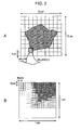
- control unit 21 controls each unit of the optical shaping apparatus 11 such that optical shaping is performed, for example, with a tiling method wherein a work entire area which is all areas where optical shaping work is performed is divided into multiple work small areas, and one-shot exposure is performed for each of the work small areas, thereby forming a hardening layer.
- a work entire area which is all areas where optical shaping work is performed is illustrated in A in Fig. 2
- work small areas which a part of the work entire area are illustrated in B in Fig. 2 .
- the work entire area is 10 cm by 10 cm
- a work small area is 1 cm by 1 cm. That is to say, the work entire area is divided into 10 by 10 work small areas.
- an area subjected to hatching around the center of the work entire area is an exposure area corresponding to the cross-sectional shape data of the three-dimensional model, and a work small area positioned at the second row from the bottom of this work entire area, and at the third column from the left is enlarged and illustrated in B in Fig. 2 .
- a profile line based on the cross-sectional shape data of the three-dimensional model is illustrated with a two-dot broken line, and light is irradiated on a unit area subjected to hatching on the inner side of the profile line thereof.
- a work small area is divided into 1000 by 1000 unit areas according to a pixel of the spatial light modulator 17 (i.e., areas corresponding to one pixel of the spatial light modulator 17).
- a work small area is 1 cm by 1 cm, so a unit area is 10 ⁇ m by 10 ⁇ m.
- the hardening layer can be formed with high precision, and consequently, the dimensional precision of a three-dimensional model can be improved.
- the ultraviolet hardening resin 31 when light is irradiated and hardened, the ultraviolet hardening resin 31 is contracted, for example, with a contracting ratio of around 7%.
- the ultraviolet hardening resin 31 is thus hardened and contracted, and accordingly, for example, the ultraviolet hardening resin 31 is hardened and contracted for each work small area where one-shot exposure is performed, joint strength between adjacent work small areas may be impaired, or the dimensional precision of the hardening layer may deteriorate.
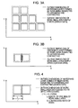
- Figs. 3A and 3B the outside dimensions of work small area data generated by simply dividing the cross-sectional shape data (design data) are shown with a dotted line, and the outside dimensions of a hardening layer formed by light being irradiated based on the work small area data thereof, and the ultraviolet hardening resin 31 being hardened and contracted are shown with a solid line.
- a gap occurs between hardening layers formed by the ultraviolet hardening resin 31 being hardened and contracted.
- Such a gap is hardened, for example, by post-hardening (hardening due to light being irradiated at subsequent processing), but with an area where the gap thereof is hardened, i.e., an area subjected to hatching in Fig. 3B , the strength thereof deteriorates as compared to the hardening layers of the work small areas, and accordingly, joint strength between the hardening layers of the work small areas deteriorates.
- the dimension precision of the hardening layers corresponding to the entire exposure area deteriorates due to occurrence of such a gap.
- the work small area data obtained by dividing the cross-sectional shape data is subjected to offset processing wherein the work small area data obtained by dividing the cross-sectional shape data is enlarged with offset width based on the contracting ratio of the ultraviolet hardening resin 31, and light is irradiated on an area which is wider than the work small area by the offset width, thereby forming a hardening layer of the work small area.
- the length of one side of work small area data generated by simply dividing the cross-sectional shape data is L
- the contracting ratio of the ultraviolet hardening resin 31 is S
- the length L' of one side of the work small area data subjected to the offset processing is thus determined based on the contracting ratio S of the ultraviolet hardening resin 31, so the length of one side of the hardening layer formed by light being irradiated and the ultraviolet hardening resin 31 being hardened and contracted based on the work small area data subjected to the offset processing is equal to the length L of one side of the work small area data generated by simply dividing the cross-sectional shape data. That is to say, the hardening layer having the outside dimensions following the design data is obtained.
- light is irradiated such that adjacent work small areas are overlapped by predetermined offset width, whereby the strength of one layer worth of hardening layer can further be enhanced.
- offset for enabling adjacent work small areas to be overlapped mutually With reference to Fig. 5 .
- offset to be performed based on the contracting ratio of the ultraviolet hardening resin 31 will be referred to as first offset
- offset for enabling adjacent work small areas to be overlapped mutually will be referred to as second offset.
- Work small areas disposed 3 by 3 are shown in Fig. 5 . '
- the work small area data is enlarged such that an area which is wider by offset amount ⁇ is irradiated based on the contracting ratio S of the ultraviolet hardening resin 31.
- the offset amount ⁇ can be set to an arbitrary numeric value, and for example, can be set to around 10 ⁇ m.
- the hardening layer of an area which has been subjected to hatching with the outside dimensions after hardening is formed. That is to say, a hardening layer is formed, which has been overlapped with adjacent work small areas on the upper side and right side of the work small area on the lower left with width corresponding to the offset amount ⁇ .
- a hardening layer is formed so as to be overlapped with adjacent work small areas, whereby junction between adjacent hardening layers can be further reinforced.
- a border line between adjacent work small areas is offset, so border lines which are not adjacent to work small areas (e.g., with the example in Fig. 5 , border lines on the left and lower sides of a work small area to be exposed) do not have to be offset. That is to say, the offset processing method has to be changed depending on the position of a work small area.
- control unit 21 when dividing an exposure area into work small areas, adds a symbol for identifying each of work small areas according to the order to be exposed, and sets a flag indicating presence/absence of adjacent work small areas to each of the work small areas, and the second offset is processed based on the flag thereof.
- Figs. 6A through 6C Similar to Fig. 5 , nine work small areas disposed so as to be 3 by 3 are illustrated, for example, symbols T 1 through T 9 are appended to each of the work small areas in the raster scan order from the lower left to the upper right according to the order to be exposed.
- the second offset as to the work small area T 1 will be described in Fig. 6A
- the second offset as to the work small area T 4 will be described in Fig. 6B
- the second offset as to the work small area T 5 will be described in Fig. 6C .
- the work small area T 1 is disposed at the lower left, the work small area T 2 is adjacent to the right side of the work small area T 1 , and the work small area T 4 is adjacent to the upper side of the work small area T 1 . Accordingly, when dividing an exposure area into work small areas, the control unit 21 sets a flag indicating presences of work small areas adjacent to the right and upper sides of the work small area T 1 .
- a flag X_FLG(+) indicating presence/absence of a work small area adjacent to the right side of the work small area is set to "1" indicating presence of an adjacent work small area
- a flag Y_FLG(+) indicating presence/absence of a work small area adjacent to the upper side of the work small area is set to "1" indicating presence of an adjacent work small area.
- a flag X_FLG(-) indicating presence/absence of a work small area adjacent to the left side of the work small area is set to "0" indicating absence of an adjacent work small area
- a flag Y_FLG(-) indicating presence/absence of a work small area adjacent to the lower side of the work small area is set to "0" indicating absence of an adjacent work small area.
- processing is performed wherein a border line between the work small area T 1 and work small area T 2 is offset to the right side, and a border line between the work small area T 1 and work small area T 4 is offset to the upper side.
- the work small area T 4 is disposed on the left side at the center, the work small area T 5 is adjacent to the right side of the work small area T 4 , the work small area T 7 is adjacent to the upper side of the work small area T 4 , and the work small area T 1 is adjacent to the lower side of the work small area T 4 . Accordingly, when dividing an exposure area into work small areas, the control unit 21 sets a flag indicating presences of work small areas adjacent to the right, upper, and lower sides of the work small area T 4 .
- a flag X_FLG(+) indicating presence/absence of a work small area adjacent to the right side of the work small area is set to "1" indicating presence of an adjacent work small area
- a flag Y_FLG(+) indicating presence/absence of a work small area adjacent to the upper side of the work small area is set to "1" indicating presence of an adjacent work small area
- a flag Y_FLG(-) indicating presence/absence of a work small area adjacent to the lower side of the work small area is set to "1" indicating presence of an adjacent work small area.
- a flag X_FLG(-) indicating presence/absence of a work small area adjacent to the left side of the work small area is set to "0" indicating absence of an adjacent work small area.
- processing is performed wherein a border line between the work small area T 9 and work small area T 5 is offset to the right side, a border line between the work small area T 4 and work small area T 7 is offset to the upper side, and a border line between the work small area T 4 and work small area T 1 is offset to the lower side.
- the work small area T 5 is disposed at the center of the four directions, the work small area T 6 is adjacent to the right side of the work small area T 5 , the work small area T 4 is adjacent to the left side of the work small area T 5 , the work small area T 8 is adjacent to the upper side of the work small area T 5 , and the work small area T 2 is adjacent to the lower side of the work small area T 5 . Accordingly, when dividing an exposure area into work small areas, the control unit 21 sets a flag indicating presences of work small areas adjacent to the right, left, upper, and lower sides of the work small area T 5 .
- a flag X_FLG(+) indicating presence/absence of a work small area adjacent to the right side of the work small area is set to "1" indicating presence of an adjacent work small area
- a flag X_FLG(-) indicating presence/absence of a work small area adjacent to the left side of the work small area is set to "1" indicating presence of an adjacent work small area.
- a flag Y_FLG(+) indicating presence/absence of a work small area adjacent to the upper side of the work small area is set to "1" indicating presence of an adjacent work small area
- a flag Y_FLG(-) indicating presence/absence of a work small area adjacent to the lower side of the work small area is set to "1" indicating presence of an adjacent work small area.
- processing is performed wherein a border line between the work small area T 5 and work small area T 6 is offset to the right side, a border line between the work small area T 5 and work small area T 4 is offset to the left side, a border line between the work small area T 5 and work small area T 8 is offset to the upper side, and a border line between the work small area T 5 and work small area T 2 is offset to the lower side.
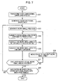
- Fig. 7 is a flowchart for describing processing for performing optical shaping according to the optical shaping apparatus 11 in Fig. 1 .
- the control unit 21 executes a program for transforming the three-dimensional shape data of the three-dimensional model created by CAD into STL to transform the three-dimensional shape data of the three-dimensional model into STL.
- step S11 the processing proceeds to step S12, where the control unit 21 generates the cross-sectional shape data of the three-dimensional model from the three-dimensional shape data transformed into STL, and the processing proceeds to step S13. Also, when generating the cross-sectional shape data of the three-dimensional model, for example, the attitude and orientation of the three-dimensional model are determined, and data for shaping a member for preventing the three-dimensional model from falling during shaping, and so forth are generated.
- step S13 the control unit 21 divides one layer of cross-sectional shape data to be processed (e.g., first, the cross-sectional shape data of the lowermost layer) according to work small areas, and creates (generates) work small area data.
- the control unit 21 adds a symbol for identifying each of the work small areas, and a flag indicating presence/absence of adjacent work small areas to each of the work small area data.
- step S13 the processing proceeds to step S14, where the control unit 21 subjects a work small area to be exposed to the first offset for enlarging the work small area to be exposed with the offset ⁇ based on the contracting ratio of the ultraviolet hardening resin 31 according to the order to be exposed, and the processing proceeds to step S15.
- step S15 the control unit 21 subjects the work small area to be exposed to the second offset for offsetting a border line with the offset ⁇ based on the flag added to the work small area thereof, and the processing proceeds to step S16.
- step S16 the control unit 21 supplies a driving signal for driving each pixel of the spatial light modulator 17 to the spatial light modulator 17 so as to irradiate light on a unit area serving as an irradiation area, and the spatial light modulator 17 drives each pixel such that light irradiated from the light source 12 passes through the pixel corresponding to the unit area serving as a irradiation area.
- the control unit 21 opens the shutter 13 for a predetermined exposure period to expose the irradiation area of the surface of the ultraviolet hardening resin 31.
- step S16 the processing proceeds to step S17, where the control unit 21 determines whether or not exposure based on one layer worth of all of work small area data generated in step S13 has been performed.
- step S17 the control unit 21 has determined that exposure based on one layer worth of all of work small area data has not been performed
- the processing proceeds to step S18, where the control unit 21 controls the driving unit 34 to move the stage 33 such that exposure is performed upon the next work small area of the work small area wherein exposure has been performed in step S16 which is immediately before step S17.
- step S18 After the processing in step S18, the processing returns to step S14, where the same processing is repeated with the next work small area of the work small area wherein exposure is performed in the last step S16 as a processing target.
- step S17 the control unit 21 has determined that exposure based on one layer worth of all of work small area data has been performed
- the processing proceeds to step S19, where the control unit 21 determines regarding whether or not exposure based on all of the cross-sectional shape data generated in step S12 has been performed.
- step S19 the control unit 21 has determined that exposure based on all of the cross-sectional shape data has not been performed, the processing returns to step S13, where the same processing is repeated with the cross-sectional shape data of the next layer of the layer wherein exposure is performed in the last steps S13 through S16 as a processing target.
- step S19 the control unit 21 has determined that exposure based on all of the cross-sectional shape data has been performed, the three-dimensional model is completed, and the processing is ended.
- the optical shaping apparatus 11 subjects the work small area data to the first offset and second offset, exposes an area wider than a work small area, so as described with reference to Fig. 5 , the strength of one layer worth of hardening layers can be enhanced. Also, such as described with reference to Figs. 3A and 3B , deterioration in dimensional precision due to occurrence of a gap can be prevented, and accordingly, the hardening layer can be shaped in a high-precision manner. Accordingly, a three-dimensional model shaped by such a hardening layer being layered can be shaped with high precision and high strength.
- a microchip, connector, microcapsule, or the like, or a prototype of various types of fine component can be shaped by employing such an optical shaping apparatus 11.
- a three-dimensional model shaped by employing the optical shaping apparatus 11 is shaped with high strength, so when coating this with nickel or the like, and transferring the model thereof, such coating is prevented from peeling off for each of the work small areas.
- a digital micromirror device made up of multiple minute reflection mirrors being arrayed wherein the tilt angle is changed according to an input signal, reflective liquid crystal on silicon (LCOS), or the like may be employed as the spatial light modulator 17.
- LCOS reflective liquid crystal on silicon
- each micromirror corresponds to one unit area, so the polarizing plate 14 does not have to be provided.
- work small area data is subjected to both of the first offset and second offset processing, but small area data may be subjected to one of the first offset and second offset, and in this case, a three-dimensional model can be shaped with higher strength as compared to a three-dimensional model according to the related art:
- an arrangement may be made wherein an irradiation area of the surface of the ultraviolet hardening resin 31 is subjected to one-shot exposure through the spatial light modulator 17, and a beam scanning exposure wherein an optical beam is scanned along the profile line of the irradiation area.
- one-shot exposure and beam scanning exposure enables a three-dimensional model to be shaped with higher precision.
- the present invention may be applied to not only the optical shaping apparatus 11 for performing optical shaping by a free liquid level method which is a technique wherein light subjected to spatial modulation by the spatial light modulator 17 is irradiated from above the ultraviolet hardening resin 31, but also an optical shaping apparatus for performing optical shaping by a fluid surface regulation method which is a technique wherein light subjected to spatial modulation by the spatial light modulator 17 is irradiated on the interface between the ultraviolet hardening resin 31 and housing container 32.
- the bottom face of the housing container 32 is configured of a material for transmitting light, such as glass or the like, and light subjected to spatial modulation by the spatial light modulator 17 is irradiated on the interface between the glass thereof and ultraviolet hardening resin 31 from the lower portion of the ultraviolet hardening resin 31. That is to say, the surface of the ultraviolet hardening resin 31 where light corresponding to the cross-sectional shape data of a three-dimensional model is irradiated includes the interface between the glass and ultraviolet hardening resin 31.
- processing is repeated wherein the stage 33 is disposed such that the distance between the housing container 32 and stage 33 is equal to the thickness of one layer worth of hardening layers, and the stage 33 is driven upward in the vertical direction such that the distance between the housing container 32 and stage 33 is equal to the thickness of one layer worth of hardening layers step by step in response to one hardening layer of a three-dimensional model being formed according to light irradiated on the ultraviolet hardening resin 31 through the glass of the bottom face of the housing container 32, thereby forming the three-dimensional model.
- the surface (interface) of the ultraviolet hardening resin 31 where light is irradiated is regulated by glass, thereby shaping the thickness of one layer worth of hardening layers accurately, so layering precision can be improved, and thus, a three-dimensional model can be formed with high precision.
- control unit 21 can be executed by not only hardware but also software.
- a program making up the software is installed from a program recording medium to a computer embedded in dedicated hardware, or a general-purpose personal computer or the like capable of executing various types of function by various types of program being installed.
- Fig. 8 is a block diagram illustrating a configuration example of a computer wherein the above-mentioned series of processing is executed by the program.
- a CPU Central Processing Unit
- ROM Read Only Memory
- RAM Random Access Memory
- An input/output interface 105 is further connected to the bus 104.
- the input/output interface 105 is connected with an input unit 106 made up of a keyboard, mouse, microphone and so forth, an output unit 107 made up of a display, speaker, and so forth, a storing unit 108 made up of a hard disk, nonvolatile memory, and so forth, a communication unit 109 made up of a network interface and so forth, and a drive 110 for driving a removable medium 111 such as a magnetic disk, optical disc, magneto-optical disk, semiconductor memory, or the like.
- the above-mentioned series of processing is performed, for example, by the CPU 101 loading a program stored in the storing unit 108 in the RAM 103 through the input/output interface 105 and bus 104 and executing this.
- the program executed by the computer (CPU 101) is provided by being recorded in the removable medium 111 which is a package medium made up of a magnetic disk (including a flexible disk), optical disc (CD-ROM (Compact Disc-Read Only Memory), DVD (Digital Versatile Disc), etc.), magneto-optical disk, semiconductor memory, or the like, or provided through a cable or wireless transmission medium such as a local area network, the Internet, or digital satellite broadcasting.
- a magnetic disk including a flexible disk
- optical disc CD-ROM (Compact Disc-Read Only Memory), DVD (Digital Versatile Disc), etc.
- magneto-optical disk semiconductor memory, or the like
- semiconductor memory or the like
- a cable or wireless transmission medium such as a local area network, the Internet, or digital satellite broadcasting.
- the removable medium 111 is mounted on the drive 110, whereby the program can be installed in the storing unit 108 through the input/output interface 105. Also, the program can be received at the communication unit 109 through a cable or wireless transmission medium, and installed in the storing unit 108. Alternatively, the program can be installed in the ROM 102 or storing unit 108 beforehand.
- the program executed by the computer may be a program wherein processing is performed in time sequence along the order described in the present Specification, or may be a program wherein processing is performed in parallel or at appropriate timing such that calling is performed.
- the program may be processed by one CPU, or may be processed by multiple CPUs in a distributed manner.
Landscapes
- Chemical & Material Sciences (AREA)
- Engineering & Computer Science (AREA)
- Materials Engineering (AREA)
- Physics & Mathematics (AREA)
- Optics & Photonics (AREA)
- Manufacturing & Machinery (AREA)
- Mechanical Engineering (AREA)
Claims (6)
- Dispositif de mise en forme optique (11) configuré pour rayonner une lumière conformément aux données de forme en coupe d'un modèle tridimensionnel sur la surface d'une résine à durcissement à la lumière (31) pour former une couche de durcissement, et déposer ladite couche de durcissement pour former ledit modèle tridimensionnel, comprenant :des moyens de génération de données (21) configurés pour diviser les données de forme en coupe dudit modèle tridimensionnel conformément à de petites zones de travail (T1 à T9) obtenues en divisant une zone entière de travail dans laquelle le travail de mise en forme optique est effectué en une pluralité de zones, et générer des données de petites zones de travail qui sont des données de forme en coupe correspondant auxdites petites zones de travail (T1 à T9) ;caractérisé en ce qu'il comprend en outre :des moyens d'agrandissement (21) configurés pour agrandir lesdites données de petites zones de travail d'une largeur de décalage sur la base du rapport de contraction (S) de ladite résine à durcissement à la lumière (31) ; etdes moyens d'exposition en une seule fois (12 à 19) configurés pour soumettre des zones, qui sont plus larges que lesdites petites zones de travail (T1 à T9) sur la surface de ladite résine à durcissement à la lumière (31) de ladite largeur de décalage, à une exposition en une seule fois sur la base desdites données de petites zones de travail agrandies par lesdits moyens d'agrandissement (21) pour former ladite couche de durcissement pour chacune desdites petites zones de travail (T1 à T9) .
- Dispositif de mise en forme optique selon la revendication 1, comprenant en outre :des moyens d'ajout (21) configurés pour ajouter des données d'une certaine largeur à partir d'une ligne de frontière entre une petite zone de travail prédéterminée desdites petites zones de travail (T1 à T9) et d'autres petites zones de travail, de données de petites zones de travail correspondant auxdites autres petites zones de travail adjacentes à ladite petite zone de travail prédéterminée, auxdites données de petites zones de travail correspondant à ladite petite zone de travail prédéterminée, décalant de ce fait ladite ligne de frontière de ladite petite zone de travail prédéterminée ;dans lequel lesdits moyens d'exposition en une seule fois (12 à 19) soumettent des zones, qui sont plus larges que lesdites petites zones de travail (T1 à T9) sur la surface de ladite résine à durcissement à la lumière (31) d'une largeur obtenue en ajoutant ladite certaine largeur et ladite largeur de décalage, à une exposition en une seule fois sur la base desdites données de petites zones de travail décalées par lesdits moyens d'ajout (21), et agrandies par lesdits moyens d'agrandissement (21).
- Procédé de mise en forme optique adapté pour rayonner une lumière conformément aux données de forme en coupe d'un modèle tridimensionnel sur la surface d'une résine à durcissement à la lumière (31) pour former une couche de durcissement, et disposer ladite couche de durcissement pour former ledit modèle tridimensionnel, comprenant les étapes consistant à :diviser les données de forme en coupe dudit modèle tridimensionnel conformément à de petites zones de travail (T1 à T9) obtenues en divisant une zone entière de travail dans laquelle un travail de mise en forme optique est effectué, en une pluralité de zones, et générer les données de petites zones de travail qui sont des données de forme en coupe correspondant auxdites petites zones de travail (T1 à T9) ;caractérisé en ce qu'il comprend en outre les étapes consistant à :agrandir lesdites données de petites zones de travail d'une largeur de décalage sur la base du rapport de contraction (S) de ladite résine à durcissement à la lumière (31) ; etsoumettre les zones, qui sont plus larges que lesdites petites zones de travail (T1 à T9) sur la surface de ladite résine à durcissement à la lumière (31) de ladite largeur de décalage, à une exposition en une seule fois sur la base desdites données de petites zones de travail pour former ladite couche de durcissement pour chacune desdites petites zones de travail (T1 à T9) .
- Dispositif de mise en forme optique (11) configuré pour rayonner une lumière conformément aux données de forme en coupe d'un modèle tridimensionnel sur la surface d'une résine à durcissement à la lumière (31) pour former une couche de durcissement, et déposer ladite couche de durcissement pour former ledit modèle tridimensionnel, comprenant :des moyens de génération de données (21) configurés pour diviser les données de forme en coupe dudit modèle tridimensionnel conformément à de petites zones de travail (T1 à T9) obtenues en divisant une zone entière de travail dans laquelle un travail de mise en forme optique est effectué en une pluralité de zones, et générer des données de petites zones de travail qui sont des données de forme en coupe correspondant auxdites petites zones de travail (T1 à T9) ;caractérisé en ce qu'il comprend en outre :des moyens d'ajout (21) configurés pour ajouter des données d'une certaine largeur à partir d'une ligne de frontière entre une petite zone de travail prédéterminée desdites petites zones de travail (T1 à T9) et d'autres petites zones de travail, de données de petites zones de travail correspondant auxdites autres petites zones de travail adjacentes à ladite petite zone de travail prédéterminée, auxdites données de petites zones de travail correspondant à ladite petite zone de travail prédéterminée, décalant de ce fait ladite ligne de frontière de ladite petite zone de travail prédéterminée ; etdes moyens d'exposition en une seule fois (12 à 19) configurés pour soumettre des zones, qui sont plus larges que lesdites petites zones de travail (T1 à T9) sur la surface de ladite résine à durcissement à la lumière (31) de ladite certaine largeur, à une exposition en une seule fois sur la base desdites données de petites zones de travail décalées par lesdits moyens d'ajout (21) pour former ladite couche de durcissement pour chacune desdites petites zones de travail (T1 à T9 ).
- Dispositif de mise en forme optique selon la revendication 4, comprenant en outre :des moyens d'agrandissement (21) configurés pour agrandir lesdites données de petites zones de travail d'une largeur de décalage sur la base du rapport de contraction (S) de ladite résine à durcissement à la lumière (31) ;dans lequel lesdits moyens d'exposition en une seule fois (12 à 19) soumettent des zones, qui sont plus larges que lesdites petites zones de travail (T1 à T9) sur la surface de ladite résine à durcissement à la lumière (31) d'une largeur obtenue en ajoutant ladite certaine largeur et ladite largeur de décalage, à une exposition en une seule fois sur la base desdites données de petites zones de travail agrandies par lesdits moyens d'agrandissement (21), et décalées par lesdits moyens d'ajout (21).
- Procédé de mise en forme optique adapté pour rayonner une lumière conformément aux données de forme en coupe d'un modèle tridimensionnel sur la surface d'une résine à durcissement à la lumière (31) pour former une couche de durcissement, et déposer ladite couche de durcissement pour former ledit modèle tridimensionnel, comprenant les étapes consistant à :diviser les données de forme en coupe dudit modèle tridimensionnel conformément à de petites zones de travail (T1 à T9) obtenues en divisant une zone entière de travail dans laquelle un travail de mise en forme optique est effectué en une pluralité de zones, et générer des données de petites zones de travail qui sont des données de forme en coupe correspondant auxdites petites zones de travail (T1 à T9) ;caractérisé en ce qu'il comprend en outre les étapes consistant à :ajouter des données d'une certaine largeur à partir d'une ligne de frontière entre une petite zone de travail prédéterminée desdites petites zones de travail (T1 à T9) et d'autres petites zones de travail, de données de petites zones de travail correspondant auxdites autres petites zones de travail adjacentes à ladite petite zone de travail prédéterminée, auxdites données de petites zones de travail correspondant à ladite petite zone de travail prédéterminée, décalant de ce fait ladite ligne de frontière de ladite petite zone de travail prédéterminée ; etsoumettre des zones, qui sont plus larges que lesdites petites zones de travail (T1 à T9) sur la surface de ladite résine à durcissement à la lumière (31) de ladite certaine largeur, à une exposition en une seule fois sur la base desdites données de petites zones de travail pour former ladite couche de durcissement pour chacune desdites petites zones de travail (T1 à T9) .
Applications Claiming Priority (1)
| Application Number | Priority Date | Filing Date | Title |
|---|---|---|---|
| JP2007312027A JP5234315B2 (ja) | 2007-12-03 | 2007-12-03 | 光造形装置および光造形方法 |
Publications (2)
| Publication Number | Publication Date |
|---|---|
| EP2067610A1 EP2067610A1 (fr) | 2009-06-10 |
| EP2067610B1 true EP2067610B1 (fr) | 2011-11-02 |
Family
ID=40227791
Family Applications (1)
| Application Number | Title | Priority Date | Filing Date |
|---|---|---|---|
| EP08020458A Not-in-force EP2067610B1 (fr) | 2007-12-03 | 2008-11-25 | Appareil de formation optique et procédé de formation optique |
Country Status (4)
| Country | Link |
|---|---|
| US (1) | US7670541B2 (fr) |
| EP (1) | EP2067610B1 (fr) |
| JP (1) | JP5234315B2 (fr) |
| AT (1) | ATE531507T1 (fr) |
Cited By (2)
| Publication number | Priority date | Publication date | Assignee | Title |
|---|---|---|---|---|
| DE102011012484A1 (de) * | 2011-02-25 | 2012-08-30 | Nanoscribe Gmbh | Verfahren und Vorrichtung zum ortsaufgelösten Einbringen eines Intensitätsmusters aus elektromagnetischer Strahlung in eine photosensitive Substanz sowie Verwendung hiervon |
| WO2018024872A1 (fr) | 2016-08-05 | 2018-02-08 | Karlsruher Institut für Technologie | Procédé et dispositif de génération lithographique d'une structure cible sur une structure initiale non plane |
Families Citing this family (16)
| Publication number | Priority date | Publication date | Assignee | Title |
|---|---|---|---|---|
| JP5293993B2 (ja) * | 2008-01-09 | 2013-09-18 | ソニー株式会社 | 光造形装置および光造形方法 |
| KR101711376B1 (ko) * | 2010-05-03 | 2017-03-02 | 주식회사 이오테크닉스 | 디지털 3차원 리소그래피 방법 및 장치 |
| JP5724317B2 (ja) * | 2010-11-18 | 2015-05-27 | ソニー株式会社 | 3次元造形装置 |
| FR3000698B1 (fr) * | 2013-01-09 | 2015-02-06 | Phidias Technologies | Fabrication d'un objet en volume par lithographie, a resolution spatiale amelioree |
| JP2015058678A (ja) * | 2013-09-20 | 2015-03-30 | インターナショナル・ビジネス・マシーンズ・コーポレーションInternational Business Machines Corporation | レーザ照射で形成される3次元構造物の寸法と当該3次元構造物のスキャンパスの設計値との差を最小化するためのデータを作成する方法、並びに当該データを作成するためのコンピュータ及びコンピュータ・プログラム |
| AT516769B1 (de) * | 2015-01-22 | 2017-12-15 | Way To Production Gmbh | Verfahren zur Belichtung eines dreidimensionalen Bereichs |
| US10688733B2 (en) * | 2015-11-25 | 2020-06-23 | The Boeing Company | Method and apparatus for three-dimensional printing |
| JP6833431B2 (ja) | 2016-09-29 | 2021-02-24 | キヤノン株式会社 | 光造形装置、光造形方法および光造形プログラム |
| JP6849365B2 (ja) | 2016-09-29 | 2021-03-24 | キヤノン株式会社 | 光造形装置、光造形方法および光造形プログラム |
| JP6800679B2 (ja) * | 2016-09-29 | 2020-12-16 | キヤノン株式会社 | 光造形装置、光造形方法および光造形プログラム |
| JP6786332B2 (ja) | 2016-09-29 | 2020-11-18 | キヤノン株式会社 | 光造形装置、光造形方法および光造形プログラム |
| CN106313504A (zh) * | 2016-10-13 | 2017-01-11 | 广州黑格智能科技有限公司 | 一种3d打印机的光固方法 |
| US20190129308A1 (en) * | 2017-11-02 | 2019-05-02 | Taiwan Green Point Enterprises Co., Ltd. | Digital masking system, pattern imaging apparatus and digital masking method |
| CN115592953B (zh) * | 2021-06-28 | 2024-03-12 | 广州黑格智造信息科技有限公司 | 用于3d打印的固化处理方法、系统、装置及存储介质 |
| US20240059022A1 (en) * | 2022-08-18 | 2024-02-22 | General Electric Company | Systems and methods for additive manufacturing using pixel shifting |
| US20240059023A1 (en) * | 2022-08-18 | 2024-02-22 | General Electric Company | Systems and methods for additive manufacturing using pixel shifting |
Family Cites Families (9)
| Publication number | Priority date | Publication date | Assignee | Title |
|---|---|---|---|---|
| US6036911A (en) * | 1988-04-18 | 2000-03-14 | 3D Systems, Inc. | Method of making a three-dimensional object by stereolithography |
| US5609813A (en) * | 1988-04-18 | 1997-03-11 | 3D Systems, Inc. | Method of making a three-dimensional object by stereolithography |
| US5182055A (en) * | 1988-04-18 | 1993-01-26 | 3D Systems, Inc. | Method of making a three-dimensional object by stereolithography |
| JPH0695257A (ja) | 1992-09-11 | 1994-04-08 | Dainippon Screen Mfg Co Ltd | 画像記録装置 |
| JPH10180881A (ja) * | 1996-12-26 | 1998-07-07 | Toshiba Corp | 光造形装置 |
| US6207097B1 (en) * | 1998-02-18 | 2001-03-27 | Norma Jean Iverson | Method for manufacturing physical objects using precision stereolithography |
| US6399010B1 (en) * | 1999-02-08 | 2002-06-04 | 3D Systems, Inc. | Method and apparatus for stereolithographically forming three dimensional objects with reduced distortion |
| JP4525424B2 (ja) * | 2005-03-30 | 2010-08-18 | Jsr株式会社 | 光造形方法 |
| JP4684943B2 (ja) | 2006-05-17 | 2011-05-18 | 株式会社日立製作所 | 緊急通信指令システム |
-
2007
- 2007-12-03 JP JP2007312027A patent/JP5234315B2/ja not_active Expired - Fee Related
-
2008
- 2008-11-25 EP EP08020458A patent/EP2067610B1/fr not_active Not-in-force
- 2008-11-25 AT AT08020458T patent/ATE531507T1/de active
- 2008-12-02 US US12/326,290 patent/US7670541B2/en active Active
Cited By (5)
| Publication number | Priority date | Publication date | Assignee | Title |
|---|---|---|---|---|
| DE102011012484A1 (de) * | 2011-02-25 | 2012-08-30 | Nanoscribe Gmbh | Verfahren und Vorrichtung zum ortsaufgelösten Einbringen eines Intensitätsmusters aus elektromagnetischer Strahlung in eine photosensitive Substanz sowie Verwendung hiervon |
| DE102011012484B4 (de) | 2011-02-25 | 2025-08-14 | Nanoscribe Holding Gmbh | Verfahren und Vorrichtung zum ortsaufgelösten Einbringen eines Intensitätsmusters aus elektromagnetischer Strahlung in eine photosensitive Substanz sowie Verwendung hiervon |
| WO2018024872A1 (fr) | 2016-08-05 | 2018-02-08 | Karlsruher Institut für Technologie | Procédé et dispositif de génération lithographique d'une structure cible sur une structure initiale non plane |
| US11143966B2 (en) | 2016-08-05 | 2021-10-12 | Karlsruhe Institute Of Technology | Method and device for lithographically producing a target structure on a non-planar initial structure |
| US11630394B2 (en) | 2016-08-05 | 2023-04-18 | Karlsruhe Institute Of Technology | Method and device for lithographically producing a target structure on a non-planar initial structure |
Also Published As
| Publication number | Publication date |
|---|---|
| US7670541B2 (en) | 2010-03-02 |
| JP5234315B2 (ja) | 2013-07-10 |
| EP2067610A1 (fr) | 2009-06-10 |
| ATE531507T1 (de) | 2011-11-15 |
| JP2009132126A (ja) | 2009-06-18 |
| US20090140466A1 (en) | 2009-06-04 |
Similar Documents
| Publication | Publication Date | Title |
|---|---|---|
| EP2067610B1 (fr) | Appareil de formation optique et procédé de formation optique | |
| EP2067607B1 (fr) | Appareil de formation optique et procédé de formation optique | |
| EP2067608A1 (fr) | Appareil de formation optique et procédé de formation optique | |
| JP5293993B2 (ja) | 光造形装置および光造形方法 | |
| EP1935620B1 (fr) | Appareil de modélisation optique et méthode de modélisation optique | |
| US7758329B2 (en) | Optical modeling apparatus | |
| EP3600844B1 (fr) | Impression 3d d'un objet ayant des surfaces lisses incurvées | |
| CN101151141A (zh) | 光成型方法 | |
| CN110325918B (zh) | 直接成像曝光装置以及直接成像曝光方法 | |
| JP5023975B2 (ja) | 光造形装置及び光造形方法 | |
| EP1449636B1 (fr) | Appareil de photofabrication | |
| JP2002331591A (ja) | 光造形方法 | |
| JP2009113294A (ja) | 光造形装置及び光造形方法 | |
| JP2009083240A (ja) | 光造形装置 | |
| JP5071114B2 (ja) | 光造形装置および光造形方法 | |
| JP2009160859A (ja) | 光造形装置および光造形方法、並びに光造形物 | |
| US7724410B2 (en) | Optical beam scanning apparatus, method of manufacturing optical beam scanning apparatus, image forming apparatus and method of manufacturing image forming apparatus | |
| CN114690574B (zh) | 一种3d曝光系统及方法 | |
| JP2009132125A (ja) | 光造形装置および光造形方法 | |
| US20040197715A1 (en) | Lenticular printing | |
| JP2009137230A (ja) | 光造形装置 |
Legal Events
| Date | Code | Title | Description |
|---|---|---|---|
| PUAI | Public reference made under article 153(3) epc to a published international application that has entered the european phase |
Free format text: ORIGINAL CODE: 0009012 |
|
| AK | Designated contracting states |
Kind code of ref document: A1 Designated state(s): AT BE BG CH CY CZ DE DK EE ES FI FR GB GR HR HU IE IS IT LI LT LU LV MC MT NL NO PL PT RO SE SI SK TR |
|
| AX | Request for extension of the european patent |
Extension state: AL BA MK RS |
|
| 17P | Request for examination filed |
Effective date: 20091209 |
|
| AKX | Designation fees paid |
Designated state(s): AT CH DE LI |
|
| 17Q | First examination report despatched |
Effective date: 20100212 |
|
| GRAP | Despatch of communication of intention to grant a patent |
Free format text: ORIGINAL CODE: EPIDOSNIGR1 |
|
| GRAS | Grant fee paid |
Free format text: ORIGINAL CODE: EPIDOSNIGR3 |
|
| GRAA | (expected) grant |
Free format text: ORIGINAL CODE: 0009210 |
|
| AK | Designated contracting states |
Kind code of ref document: B1 Designated state(s): AT CH DE LI |
|
| REG | Reference to a national code |
Ref country code: CH Ref legal event code: EP |
|
| REG | Reference to a national code |
Ref country code: DE Ref legal event code: R096 Ref document number: 602008011003 Country of ref document: DE Effective date: 20111229 |
|
| REG | Reference to a national code |
Ref country code: CH Ref legal event code: NV Representative=s name: ISLER & PEDRAZZINI AG |
|
| PLBE | No opposition filed within time limit |
Free format text: ORIGINAL CODE: 0009261 |
|
| STAA | Information on the status of an ep patent application or granted ep patent |
Free format text: STATUS: NO OPPOSITION FILED WITHIN TIME LIMIT |
|
| 26N | No opposition filed |
Effective date: 20120803 |
|
| REG | Reference to a national code |
Ref country code: DE Ref legal event code: R097 Ref document number: 602008011003 Country of ref document: DE Effective date: 20120803 |
|
| REG | Reference to a national code |
Ref country code: DE Ref legal event code: R084 Ref document number: 602008011003 Country of ref document: DE |
|
| REG | Reference to a national code |
Ref country code: DE Ref legal event code: R084 Ref document number: 602008011003 Country of ref document: DE Effective date: 20150410 |
|
| REG | Reference to a national code |
Ref country code: DE Ref legal event code: R079 Ref document number: 602008011003 Country of ref document: DE Free format text: PREVIOUS MAIN CLASS: B29C0067000000 Ipc: B29C0064106000 |
|
| PGFP | Annual fee paid to national office [announced via postgrant information from national office to epo] |
Ref country code: DE Payment date: 20191121 Year of fee payment: 12 |
|
| PGFP | Annual fee paid to national office [announced via postgrant information from national office to epo] |
Ref country code: CH Payment date: 20191121 Year of fee payment: 12 Ref country code: AT Payment date: 20191121 Year of fee payment: 12 |
|
| REG | Reference to a national code |
Ref country code: DE Ref legal event code: R119 Ref document number: 602008011003 Country of ref document: DE |
|
| REG | Reference to a national code |
Ref country code: CH Ref legal event code: PL |
|
| REG | Reference to a national code |
Ref country code: AT Ref legal event code: MM01 Ref document number: 531507 Country of ref document: AT Kind code of ref document: T Effective date: 20201125 |
|
| PG25 | Lapsed in a contracting state [announced via postgrant information from national office to epo] |
Ref country code: AT Free format text: LAPSE BECAUSE OF NON-PAYMENT OF DUE FEES Effective date: 20201125 Ref country code: CH Free format text: LAPSE BECAUSE OF NON-PAYMENT OF DUE FEES Effective date: 20201130 Ref country code: LI Free format text: LAPSE BECAUSE OF NON-PAYMENT OF DUE FEES Effective date: 20201130 |
|
| PG25 | Lapsed in a contracting state [announced via postgrant information from national office to epo] |
Ref country code: DE Free format text: LAPSE BECAUSE OF NON-PAYMENT OF DUE FEES Effective date: 20210601 |