EP2067613A1 - Procédé et dispositif de fabrication de lentille ophtalmique utilisant un matériau photoactif - Google Patents
Procédé et dispositif de fabrication de lentille ophtalmique utilisant un matériau photoactif Download PDFInfo
- Publication number
- EP2067613A1 EP2067613A1 EP07301633A EP07301633A EP2067613A1 EP 2067613 A1 EP2067613 A1 EP 2067613A1 EP 07301633 A EP07301633 A EP 07301633A EP 07301633 A EP07301633 A EP 07301633A EP 2067613 A1 EP2067613 A1 EP 2067613A1
- Authority
- EP
- European Patent Office
- Prior art keywords
- map
- refractive index
- photoactive material
- radiation
- layer
- Prior art date
- Legal status (The legal status is an assumption and is not a legal conclusion. Google has not performed a legal analysis and makes no representation as to the accuracy of the status listed.)
- Withdrawn
Links
- 239000000463 material Substances 0.000 title claims abstract description 68
- 238000000034 method Methods 0.000 title claims abstract description 42
- 238000004519 manufacturing process Methods 0.000 title claims abstract description 29
- 230000005855 radiation Effects 0.000 claims abstract description 76
- 230000004913 activation Effects 0.000 claims abstract description 59
- 239000000758 substrate Substances 0.000 claims description 15
- 238000011065 in-situ storage Methods 0.000 claims description 7
- 238000005259 measurement Methods 0.000 claims description 7
- 238000004590 computer program Methods 0.000 claims description 6
- 230000007423 decrease Effects 0.000 claims description 5
- 239000004973 liquid crystal related substance Substances 0.000 claims description 3
- 239000011159 matrix material Substances 0.000 description 21
- 230000004075 alteration Effects 0.000 description 12
- 230000008569 process Effects 0.000 description 11
- 230000003287 optical effect Effects 0.000 description 10
- 239000000203 mixture Substances 0.000 description 7
- 229920000642 polymer Polymers 0.000 description 7
- 238000006243 chemical reaction Methods 0.000 description 6
- 230000006870 function Effects 0.000 description 6
- 230000015654 memory Effects 0.000 description 6
- 239000000178 monomer Substances 0.000 description 6
- 238000012937 correction Methods 0.000 description 5
- 210000001525 retina Anatomy 0.000 description 5
- 230000033228 biological regulation Effects 0.000 description 4
- 239000011248 coating agent Substances 0.000 description 4
- 238000000576 coating method Methods 0.000 description 4
- 201000004569 Blindness Diseases 0.000 description 3
- 239000004593 Epoxy Substances 0.000 description 3
- 238000004891 communication Methods 0.000 description 3
- WBYWAXJHAXSJNI-VOTSOKGWSA-M trans-cinnamate Chemical compound [O-]C(=O)\C=C\C1=CC=CC=C1 WBYWAXJHAXSJNI-VOTSOKGWSA-M 0.000 description 3
- 239000002253 acid Substances 0.000 description 2
- 239000000853 adhesive Substances 0.000 description 2
- 230000001070 adhesive effect Effects 0.000 description 2
- 210000004556 brain Anatomy 0.000 description 2
- CCRCUPLGCSFEDV-UHFFFAOYSA-N cinnamic acid methyl ester Natural products COC(=O)C=CC1=CC=CC=C1 CCRCUPLGCSFEDV-UHFFFAOYSA-N 0.000 description 2
- 150000001988 diarylethenes Chemical class 0.000 description 2
- 238000005516 engineering process Methods 0.000 description 2
- 238000003384 imaging method Methods 0.000 description 2
- CCRCUPLGCSFEDV-BQYQJAHWSA-N methyl trans-cinnamate Chemical compound COC(=O)\C=C\C1=CC=CC=C1 CCRCUPLGCSFEDV-BQYQJAHWSA-N 0.000 description 2
- 230000000750 progressive effect Effects 0.000 description 2
- 238000003860 storage Methods 0.000 description 2
- WBYWAXJHAXSJNI-VOTSOKGWSA-N trans-cinnamic acid Chemical compound OC(=O)\C=C\C1=CC=CC=C1 WBYWAXJHAXSJNI-VOTSOKGWSA-N 0.000 description 2
- 230000004393 visual impairment Effects 0.000 description 2
- UKFXMSBXHCEXIK-UHFFFAOYSA-N 2,3,3-tribromoprop-2-enoic acid Chemical compound OC(=O)C(Br)=C(Br)Br UKFXMSBXHCEXIK-UHFFFAOYSA-N 0.000 description 1
- OXBLVCZKDOZZOJ-UHFFFAOYSA-N 2,3-Dihydrothiophene Chemical compound C1CC=CS1 OXBLVCZKDOZZOJ-UHFFFAOYSA-N 0.000 description 1
- NIXOWILDQLNWCW-UHFFFAOYSA-M Acrylate Chemical compound [O-]C(=O)C=C NIXOWILDQLNWCW-UHFFFAOYSA-M 0.000 description 1
- 101001136034 Homo sapiens Phosphoribosylformylglycinamidine synthase Proteins 0.000 description 1
- 150000005857 PFAS Chemical class 0.000 description 1
- 102100036473 Phosphoribosylformylglycinamidine synthase Human genes 0.000 description 1
- 241000139306 Platt Species 0.000 description 1
- -1 Poly(phenylmethyl) Polymers 0.000 description 1
- 239000004793 Polystyrene Substances 0.000 description 1
- BLRPTPMANUNPDV-UHFFFAOYSA-N Silane Chemical compound [SiH4] BLRPTPMANUNPDV-UHFFFAOYSA-N 0.000 description 1
- 230000009471 action Effects 0.000 description 1
- 230000003213 activating effect Effects 0.000 description 1
- 230000005540 biological transmission Effects 0.000 description 1
- 230000008859 change Effects 0.000 description 1
- 229940114081 cinnamate Drugs 0.000 description 1
- 238000010276 construction Methods 0.000 description 1
- 229920001577 copolymer Polymers 0.000 description 1
- 230000007547 defect Effects 0.000 description 1
- 230000001419 dependent effect Effects 0.000 description 1
- 238000013461 design Methods 0.000 description 1
- 238000009792 diffusion process Methods 0.000 description 1
- 229920006332 epoxy adhesive Polymers 0.000 description 1
- 239000012948 isocyanate Substances 0.000 description 1
- 150000002513 isocyanates Chemical class 0.000 description 1
- 238000013532 laser treatment Methods 0.000 description 1
- LFEUVBZXUFMACD-UHFFFAOYSA-H lead(2+);trioxido(oxo)-$l^{5}-arsane Chemical compound [Pb+2].[Pb+2].[Pb+2].[O-][As]([O-])([O-])=O.[O-][As]([O-])([O-])=O LFEUVBZXUFMACD-UHFFFAOYSA-H 0.000 description 1
- 208000002780 macular degeneration Diseases 0.000 description 1
- QSHDDOUJBYECFT-UHFFFAOYSA-N mercury Chemical compound [Hg] QSHDDOUJBYECFT-UHFFFAOYSA-N 0.000 description 1
- 229910052753 mercury Inorganic materials 0.000 description 1
- SQDFHQJTAWCFIB-UHFFFAOYSA-N n-methylidenehydroxylamine Chemical compound ON=C SQDFHQJTAWCFIB-UHFFFAOYSA-N 0.000 description 1
- 239000002071 nanotube Substances 0.000 description 1
- 239000013307 optical fiber Substances 0.000 description 1
- 238000005457 optimization Methods 0.000 description 1
- 230000010363 phase shift Effects 0.000 description 1
- 238000006552 photochemical reaction Methods 0.000 description 1
- 238000005498 polishing Methods 0.000 description 1
- 229920000314 poly p-methyl styrene Polymers 0.000 description 1
- 229920000555 poly(dimethylsilanediyl) polymer Polymers 0.000 description 1
- 229920003229 poly(methyl methacrylate) Polymers 0.000 description 1
- 229920000058 polyacrylate Polymers 0.000 description 1
- 229920000728 polyester Polymers 0.000 description 1
- 239000004926 polymethyl methacrylate Substances 0.000 description 1
- 229920002223 polystyrene Polymers 0.000 description 1
- 206010063401 primary progressive multiple sclerosis Diseases 0.000 description 1
- 229920005989 resin Polymers 0.000 description 1
- 239000011347 resin Substances 0.000 description 1
- 230000004283 retinal dysfunction Effects 0.000 description 1
- 230000002207 retinal effect Effects 0.000 description 1
- 230000004256 retinal image Effects 0.000 description 1
- 229920006395 saturated elastomer Polymers 0.000 description 1
- 229910000077 silane Inorganic materials 0.000 description 1
- GUGNSJAORJLKGP-UHFFFAOYSA-K sodium 8-methoxypyrene-1,3,6-trisulfonate Chemical compound [Na+].[Na+].[Na+].C1=C2C(OC)=CC(S([O-])(=O)=O)=C(C=C3)C2=C2C3=C(S([O-])(=O)=O)C=C(S([O-])(=O)=O)C2=C1 GUGNSJAORJLKGP-UHFFFAOYSA-K 0.000 description 1
- 150000003573 thiols Chemical class 0.000 description 1
- 230000007704 transition Effects 0.000 description 1
- 229920002554 vinyl polymer Polymers 0.000 description 1
- 230000000007 visual effect Effects 0.000 description 1
- 238000005406 washing Methods 0.000 description 1
Images



Classifications
-
- B—PERFORMING OPERATIONS; TRANSPORTING
- B29—WORKING OF PLASTICS; WORKING OF SUBSTANCES IN A PLASTIC STATE IN GENERAL
- B29D—PRODUCING PARTICULAR ARTICLES FROM PLASTICS OR FROM SUBSTANCES IN A PLASTIC STATE
- B29D11/00—Producing optical elements, e.g. lenses or prisms
- B29D11/00009—Production of simple or compound lenses
- B29D11/00355—Production of simple or compound lenses with a refractive index gradient
-
- B—PERFORMING OPERATIONS; TRANSPORTING
- B29—WORKING OF PLASTICS; WORKING OF SUBSTANCES IN A PLASTIC STATE IN GENERAL
- B29D—PRODUCING PARTICULAR ARTICLES FROM PLASTICS OR FROM SUBSTANCES IN A PLASTIC STATE
- B29D11/00—Producing optical elements, e.g. lenses or prisms
- B29D11/0073—Optical laminates
-
- G—PHYSICS
- G02—OPTICS
- G02C—SPECTACLES; SUNGLASSES OR GOGGLES INSOFAR AS THEY HAVE THE SAME FEATURES AS SPECTACLES; CONTACT LENSES
- G02C2202/00—Generic optical aspects applicable to one or more of the subgroups of G02C7/00
- G02C2202/12—Locally varying refractive index, gradient index lenses
-
- G—PHYSICS
- G02—OPTICS
- G02C—SPECTACLES; SUNGLASSES OR GOGGLES INSOFAR AS THEY HAVE THE SAME FEATURES AS SPECTACLES; CONTACT LENSES
- G02C2202/00—Generic optical aspects applicable to one or more of the subgroups of G02C7/00
- G02C2202/14—Photorefractive lens material
Definitions
- the present invention relates generally to an ophthalmic lens manufacturing method using photo sensitive curable material which can be selectively activated to vary its index of refraction. More specifically, the present invention pertains to patient-specific spectacle lenses manufactured with a variable index aberrator in order to more accurately correct lower order aberrations and possibly correct higher order aberrations.
- lens blanks are available in discrete steps of refractive power of 0.25 diopters. In most cases, these steps may be too large to create optimum vision for a patient's eye.
- the present invention utilizes the technology developed by the wavefront aberrator in which a layer of photoactive material, which can be selectively activated to vary its index of refraction, is exposed to an activation radiation that is modulated spatially or temporally in order to create spatially resolved variations of refractive indices. This will allow the manufacturing of a lens that is capable of introducing or compensating for low and high order aberrations.
- a method for making a lens comprises imaging a patient's eye, selecting a first and a second lens, coating said first lens with a material having an index of refraction that can be changed by exposure to ultraviolet radiation, placing the second lens on said material, and activating, namely curing, it in accordance with the wavefront prescription determined by imaging the patient's eye.
- the epoxy aberrator is exposed to curing radiation in a pre-programmed way in order to fine-tune the refractive properties of the lens to the spherical and cylindrical prescription of the patient's eye and/or to a multi-focal or progressive addition lens prescription.
- the present inventors have studied the aforementioned method and discovered that the quality of the final lens is highly dependent on the method used to control the activation radiation.
- Commonly used method where the intensity of the activation radiation is locally precalculated and once locally provided to the layer of photoactive material, may lead to over-activated zones, as for example overcured zones, and to major optical defects.
- the goal of the present invention is to improve said method and enhance the quality of the final ophthalmic lens.
- the present invention and thanks to the measured resulting refractive index map over the manufacturing process, it is possible to control precisely and locally the effectiveness of the applied radiation and to avoid over activation of the photoactive material through local optimization of the activation radiation quantity over the whole process.
- the wavefront of the resulting lens can then fit very precisely with the prescribed one.
- the measured refractive index map can be measured directly or be calculated thanks to measured phase values that can be determined using wavefront measurements.
- the present method for manufacturing an ophthalmic lens using a photoactive material may be used to manufacture all the different types of ophthalmic lenses, such as spectacle lenses, trial lenses, contact lenses and for all types of prescriptions, namely spherical and/or cylindrical aberrations corrections, higher order aberrations corrections.
- Resulting lenses may be single or progressive addition lenses.
- the present invention may be used to "warp" the retinal image so that damaged portions of the retina will be bypassed by the image.
- the visual field of the patient needs to be mapped with a perimeter or micro-perimeter. From this map of healthy retina, spectacle lenses could be manufactured using the present aberrator.
- the layer of a photoactive material may be provided on a substrate, such as a lens blank. It also may be sandwiched in between two lens blanks.
- the substrate may be flat or curved.
- the substrate may have a concave and/or a convex surface.
- the substrate may be selected to improve some vision parameters of the viewer. As for an example, the substrate corrects first order vision aberrations and the activated layer corrects higher order vision aberrations.
- the activated layer corrects part or totally first order vision aberrations.
- the activated layer of a photoactive material is the final lens.
- in situ means that position of the sample when the measuring radiation is being provided is the same that the position of the sample when the activation radiation is provided. Thanks to the beam splitter both radiation can be provided to the sample when its position remains constant.
- the wavelength of the activation and measuring radiations are different and said wavelengths and the beam splitter are chosen so as the activation radiation is reflected on the beam splitter and the measuring radiation is transmitted through the same beam splitter.
- the activation and measuring radiations can be provided simultaneously or sequentially one after the other.
- Maintaining the sample with the layer of a photoactive material in a constant position may be advantageous because it avoids the photoactive material to flow as it could happen if the samples were displaced from a position to another position.
- a photoactive material which can be selectively and locally cured is a material which refractive index can either increase or decrease when an activation radiation is locally provided.
- the refractive index variation of said material can result from chemical reactions such as thermal reactions, photochemical reactions, diffusion reactions of films or from non chemical reactions such as alignment of LCs or nanotubes, opalization reactions.
- the photoactive material is chosen in the list of index decrease materials comprising Poly(phenylmethyl) Silane; Polydimethyl Silane; PolyVinyl Cinnamate (PVCm); PVCm blend comprising for example PPMS, Methyl trans-Cinnamate, trans-Cinnamate Acid; PMMA blend comprising for example Methyl trans-Cinnamate, trans-Cinnamate Acid, Nitrone; PBPMA copolymer such as P(PBPMA-co-GMA); Sol-gel hybrid films such as MPTS/PFAS.
- the photoactive material is chosen in the list of index increase materials comprising Diarylethene polymer, Pentabromo-acrylate, Thiolene adhesives, Tribromo-acrylate, Diarylethene derivative, Acrylate adhesives, Epoxy adhesives, Azobenzenes.
- the present invention also relates to a device for manufacturing an ophthalmic lens comprising:
- the present invention also relates to a computer program product comprising one or more stored sequences of instruction that is accessible to a processor and which, when executed by the processor, causes the processor to carry out the steps of preceding method for manufacturing an ophthalmic lens.
- It also relates to a computer readable medium carrying one or more sequences of instructions of the here above computer program product.
- Embodiments of the present invention may include apparatuses for performing the operations herein.
- This apparatus may be specially constructed for the desired purposes, or it may comprise a general purpose computer or Digital Signal Processor ("DSP") selectively activated or reconfigured by a computer program stored in the computer.
- DSP Digital Signal Processor
- Such a computer program may be stored in a computer readable storage medium, such as, but is not limited to, any type of disk including floppy disks, optical disks, CD-ROMs, magnetic-optical disks, read-only memories (ROMs), random access memories (RAMs) electrically programmable read-only memories (EPROMs), electrically erasable and programmable read only memories (EEPROMs), magnetic or optical cards, or any other type of media suitable for storing electronic instructions, and capable of being coupled to a computer system bus.
- a computer readable storage medium such as, but is not limited to, any type of disk including floppy disks, optical disks, CD-ROMs, magnetic-optical disks, read-only memories (ROMs), random access memories (RAMs) electrically programmable read-only memories (EPROMs), electrically erasable and programmable read only memories (EEPROMs), magnetic or optical cards, or any other type of media suitable for storing electronic instructions, and capable of being coupled to a computer system bus.
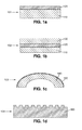
- FIG. 1 Some embodiments of lenses according to the present invention are shown on figures 1 .
- a lens 101 according to the present invention comprises a flat substrate 110 on which a layer 120 of a photoactive material is provided.
- the lens 102 of figure 1b comprises two flat substrates 110, 130 and a layer 120 of a photoactive material is provided in between the two substrates 110, 130.
- the lens 103 of figure 1c comprises a substrate 140 with a concave and a convex surface and a layer 150 of a photoactive material is provided on the convex surface of the substrate 140.
- the photoactive material is a photosensitive curable material which can be selectively and locally cured thanks to curing radiation.
- Example of lenses that can be manufactured according to the present method for manufacturing an ophthalmic lens using a photoactive material layer are disclosed from patent document FR 2 884 622 .
- the thickness of the layer 120, 150 of a photoactive material is between 0.2 and 1mm, namely 0.5mm.
- the lens 104 of figure 1d consists of a layer 160 of a photosensitive curable material where a pattern is formed on one of its surface.
- the pattern results of locally activation, namely curing, the photosensitive material to form the final relief and washing the uncured resin between said final relief.
- the photosensitive material comprises an epoxy polymer.
- the polymer is formed using a composition including a matrix polymer having a monomer mixture dispersed therein, the matrix polymer being selected from the group consisting of polyester, polystyrene, polyacrylate, thiol-cured epoxy polymer, thiol-cured isocyanate polymer, and mixtures thereof; the monomer mixture comprising a thiol monomer and at least one second monomer selected from the group consisting of ene monomer and yne monomer.
- a sheet of the photoactive material is formed. A portion of this sheet is placed on a substrate 110, 140 or between two optical elements 110, 120 to form a lens. A single large sheet can be formed in bulk with portions diced and used to form many lens blanks.
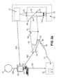
- Figure 2a shows a diagrammatic view of a device according to the present invention where a sample 100 comprising a layer of a photoactive material which can be selectively and locally activated to vary its index of refraction is locally activated thanks to an activation radiation beam, such as a Ultra Violet beam 44.
- an activation radiation beam such as a Ultra Violet beam 44.
- Said sample 100 can for example be configured and treated to form one of the preceding lenses 101, 102, 103, 104.
- the sample 100 is in situ exposed to a laser beam 76 which is used to locally measure the resulting refractive index map of the UV exposed layer of photosensitive material when or after being exposed.
- a UV beam is emitted by a UV source 30 which can be finely tuned and controlled by central computer 20 through communication line 300.
- the UV light source can include a UV Vertical Cavity Surface Emitting Laser (VSCEL), triple YAG laser, or a UV-LED.
- VSCEL UV Vertical Cavity Surface Emitting Laser
- the UV source is a LC8 UV lamp commercialized by the company Hamamatsu.
- the UV beam is transmitted through an optical fibre 31 to a lens system 32 to produce an enlarged UV beam 40.
- UV beam 40 is reflected on a mirror 33 and directed to a modulating optical system 50, such as a DLP, to obtain an UV beam 42 with a two dimensional map of intensity, which is called a two dimensional grayscale pattern.
- a shutter is coupled with the UV source.
- the shutter may be placed between the lens system 32 and the mirror 33 or on the light path after the modulating optical system 50. It is used to suitably stop the UV beam.
- the activation radiation beam is a visible light beam, emitted for example by a Mercury (Hg) lamp.
- Hg Mercury
- DMD Digital Micromirror Device
- a Texas instrument DMD known as Digital Light Projector (DLP), which operates in the UV range, such as for example at a 365 nm wavelength, can be used in the present device.
- DLP Digital Light Projector
- the DMD 50 is controlled by the central computer 20 through communication line 400.
- the two dimensional UV grayscale pattern 42 is focused by a lens or a lens group 55 to form UV beam 43 which is reflected by a beam splitter 60 and directed to sample 100 as UV beam 44.
- Beam 43 may be a converging beam.
- the sample 100 can be in situ measured thanks to an aberrometer 70 comprising for example a wavefront sensor.
- the wavefront sensor can be for example a Shack-Hartmann apparatus, diffraction grating, grating, Hartmann Screen, Fizeau interferometer, ray tracing system, Tscherning aberrometer, skiascopic phase difference system, Twymann-Green interferometer, Talbot interferometer.
- Exemplary aberrometers are described in more detail in US Patent n°6,721,043 to Platt. B. et al . in "Light Adjustable Aberration Conjugator".
- a Shack-Hartmann apparatus is used.
- a laser source 71 emits a laser beam which is parallelized by a lens 72 to form a laser beam 75.
- Said laser beam 75 is transmitted through the beam splitter 60 and directed to the sample 100.
- the Shack-Hartmann apparatus 70 comprises a Hartmann matrix 73 which is situated under the sample 100.
- the result of the Shack-Hartmann measurement is a two dimensional wavefront map of the sample 100 which can be converted in a two dimensional refractive index map of the exposed layer of the photoactive material.
- Results of the aberrometer 70 are brought to the central computer 20 through connection line 500.
- the central computer 20 is used to implement metrics to control the whole manufacturing process.
- Entrance data can be provided to the central computer 20 manually or through the communication line 200 which may be connected to an apparatus 10 suitable to measure the vision parameters of a viewer.
- Said vision parameters are used to define the final lens characteristics which include the two dimensional variable refractive index map of the desired final layer of the photoactive material.
- the lens definition can include the wave map, a pattern of refraction, a prescription in terms of sphere, cylinder, and axis, or any other relation to a pattern of refraction or correction.
- the lens definition may include an optical center, multiple optical centers, single correction zones, multiple correction zones, transition zone, blend zone, swim region, channel, add zones, vertex distance, segmental height, off-axis gaze zone, logos, invisible markings, etc..
- the two dimensional variable refractive index map is at least partially defined in terms of sphere, cylinder and axis.
- a further pattern of refraction for correcting high order aberrations and residual aberrations can be further calculated and incorporated into the two dimensional variable refractive index map.
- said refractive index map can be calculated in terms of low and high order Zernike polynomials.
- FIG. 2b shows an other diagrammatic view of a device according to the present invention where the activation radiation beam is no more reflected by a DMD, but transmitted through a transmitting liquid crystal display (LCD) 53.
- LCD liquid crystal display
- radiation is directed through a photomask to control the amount of radiation received at different points in the sample 100.
- the photomask can comprise regions that are essentially opaque to the radiation, regions that are essentially transparent to the radiation, and regions that transmit a portion of the radiation.
- the sample 100 is exposed to the radiation for a predetermined time to cure and partially cure the photosensitive material such that the pattern of refractive index is formed.
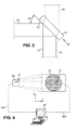
- Figure 3 shows a detailed view of the beam splitter 60 when the UV activation radiation beam 43, 44 and the laser light measuring radiation beam 75, 76 are provided to the sample 100.
- the axis of the beam splitter 60 is situated at a 45° angle from the UV beam 43 which is reflected on surface 62 of the beam splitter to form UV beam 44.
- the laser measuring radiation beam 75 is transmitted through the beam splitter 60 to form the measuring radiation beam 76.
- a beam splitter has usually two main surfaces 61 and 62, where the main surface 61 may be coated with a broadband antireflection layer and the other main surface 62 may be coated with a multilayer dielectric coating.
- the coating of the main surface 61 helps to minimize ghost beams and the coating of the main surface 62 is used to selectively reflect a range of chosen wavelengths beam.
- a beam splitter sold by the company Melles Griot under the commercial reference 424 DCLP may be used in the present device.
- Figure 4 shows diagrammatically the correspondence between the zones of the DMD 50 and the zones of the Hartmann matrix 73.
- the DMD is a 15.3 mm x 11.5 mm device and each pixel, i.e. each mirror, is a square which side is 14 ⁇ m.
- the Hartmann matrix is a 55 mm diameter device with 1 mm side square elements 77.
- the DMD reflected UV beam is magnified 4.8 times.
- a set 51 of 14 pixels of the DMD 50 corresponds to a 1 mm Hartmann matrix element 77.
- the matrix of the DMD can be written as M1 (i, j), where i and j are coordinates of the DMD device and the Hartmann matrix of the wavefront measurement can be written as M2 (x, y), where x and y are coordinates of the Hartmann matrix (same coordinates as the sample 100).
- the results of the wavefront measurement are transmitted to the central computer 20 through line 500 and said results are treated by the computer to generate a new image matrix M1'(i,j) transmitted to the DMD through line 400.
- a new wavefront measurement is performed to generate a new M2'(x,y) file which is analysed and the process goes on up to a target M2 target (x, y) file is obtained.
- Figure 5 shows a diagrammatic flow chart of an embodiment of the present method for manufacturing a lens.
- phase parameters ⁇ target (x,y) are introduced in the computer system.
- ⁇ target (x,y) is the target wavefront matrix values of the lens which is intended to be manufactured.
- Said step may comprise providing information from an apparatus 10 suitable to measure the vision parameters of a viewer, as shown on figure 2 .
- ⁇ init (x,y) is provided to the computer system in step 620.
- ⁇ init (x,y) is the initial wavefront matrix values of the sample before beginning to provide activation radiations to the photoactive material layer.
- Said step may comprise measuring the wavefront matrix values of the un-activated photoactive material layer of at least a substrate. It is also possible to introduce calculated values to define ⁇ init (x, y).
- phase values map or index values map can be first measured to respectively determine corresponding measured index values map or phase values map.
- Both ⁇ target (x,y) and ⁇ init (x,y) matrix values are used in step 630 to calculate an initial grayscale pattern u o .
- the grayscale pattern u includes the grayscale value of each point of the M1 (i,j) matrix of the DMD at a given time.
- the initial grayscale pattern u o is calculated so as to provide locally a activation radiation to the sample which will make the un-activated photoactive material layer partially vary in order to obtain locally an activation level lower than the final target activation level.
- the manufacturing system, SYST, and corresponding devices are operating in step 640 and UV light beam is provided and locally reflected by the DLP to locally modulate the activation radiation and then directed to the layer of the un-activated photoactive material of the sample to be manufactured.
- Resulting wavefront matrix values are measured at the time t1 in step 650 to determine the resulting current ⁇ meas (x,y) matrix.
- a difference function, e(t 1 ), which corresponds to the resulting values of the map of differences is calculated in step 660, where e(t) is the difference matrix between the target wavefront matrix values ⁇ target (x,y) and the measured wavefront matrix values ⁇ meas(t) (x,y) at the time t.
- the e(t 1 ) values are intentionally not nil and a second grayscale pattern u(t 1 ) (or u(t1 + ⁇ ) where ⁇ is a short time period) is calculated in steps 670 and provided to the system and its devices in a new 640 step.
- the steps 640, 650, 660, 670 correspond to a regulation loop.
- the process is repeated up to e(t) reach a threshold value TV. Namely when e(t) ⁇ TV in every local x, y position of the activated photoactive material layer, step 690 is reached which corresponds to the end of the process.
- PID proportional - integral - differential
- K p , K d , K i are chosen so that the e (t) value remains always positive and thus no over-activation of the photoactive material may occur.
- predictive command can be implemented within the regulation loop.
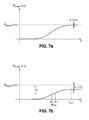
- Figure 6 shows a diagrammatic time schedule of an embodiment of the manufacturing process where measured wavefront phase value ⁇ meas (x, y) is plotted as a function of the operating time, t.
- ⁇ t i corresponds to the initialization period of the process where u o is measured.
- ⁇ t e corresponds to a time period where activation radiation, i.e. exposition time period, is provided to the sample.
- ⁇ t r corresponds to a relaxation time period where no activation radiation is provided to the sample, in order to take into account the time needed for the material to relax and to obtain a stable activated state.
- ⁇ t e + ⁇ t r is the time period corresponding to a activation cycle.
- Each ⁇ t e time period can be divided in a plurality of substeps where:
- the process ends when a threshold is reached and last exposition time period is ⁇ t e end.
- the value e(t) reaches a plateau and do not decrease anymore after the photoactive material has reached a completely activated state.
- the saturation of the material is reached at the saturation time, t sat .
Landscapes
- Engineering & Computer Science (AREA)
- Health & Medical Sciences (AREA)
- Manufacturing & Machinery (AREA)
- Ophthalmology & Optometry (AREA)
- Mechanical Engineering (AREA)
- Eyeglasses (AREA)
Priority Applications (1)
| Application Number | Priority Date | Filing Date | Title |
|---|---|---|---|
| EP07301633A EP2067613A1 (fr) | 2007-12-06 | 2007-12-06 | Procédé et dispositif de fabrication de lentille ophtalmique utilisant un matériau photoactif |
Applications Claiming Priority (1)
| Application Number | Priority Date | Filing Date | Title |
|---|---|---|---|
| EP07301633A EP2067613A1 (fr) | 2007-12-06 | 2007-12-06 | Procédé et dispositif de fabrication de lentille ophtalmique utilisant un matériau photoactif |
Publications (1)
| Publication Number | Publication Date |
|---|---|
| EP2067613A1 true EP2067613A1 (fr) | 2009-06-10 |
Family
ID=39339880
Family Applications (1)
| Application Number | Title | Priority Date | Filing Date |
|---|---|---|---|
| EP07301633A Withdrawn EP2067613A1 (fr) | 2007-12-06 | 2007-12-06 | Procédé et dispositif de fabrication de lentille ophtalmique utilisant un matériau photoactif |
Country Status (1)
| Country | Link |
|---|---|
| EP (1) | EP2067613A1 (fr) |
Cited By (12)
| Publication number | Priority date | Publication date | Assignee | Title |
|---|---|---|---|---|
| US11529230B2 (en) | 2019-04-05 | 2022-12-20 | Amo Groningen B.V. | Systems and methods for correcting power of an intraocular lens using refractive index writing |
| US11564839B2 (en) | 2019-04-05 | 2023-01-31 | Amo Groningen B.V. | Systems and methods for vergence matching of an intraocular lens with refractive index writing |
| WO2023007162A1 (fr) * | 2021-07-30 | 2023-02-02 | Coopervision International Limited | Procédé de fabrication d'une lentille ophtalmique |
| US11583388B2 (en) | 2019-04-05 | 2023-02-21 | Amo Groningen B.V. | Systems and methods for spectacle independence using refractive index writing with an intraocular lens |
| US11583389B2 (en) | 2019-04-05 | 2023-02-21 | Amo Groningen B.V. | Systems and methods for correcting photic phenomenon from an intraocular lens and using refractive index writing |
| GB2611166A (en) * | 2021-07-30 | 2023-03-29 | Coopervision Int Ltd | Ophthalmic lenses having a photopolymer layer with grin elements |
| GB2611164A (en) * | 2021-07-30 | 2023-03-29 | Coopervision Int Ltd | Films having grin elements for application to spectacles or other ophthalmic lenses |
| US11678975B2 (en) | 2019-04-05 | 2023-06-20 | Amo Groningen B.V. | Systems and methods for treating ocular disease with an intraocular lens and refractive index writing |
| US11944574B2 (en) | 2019-04-05 | 2024-04-02 | Amo Groningen B.V. | Systems and methods for multiple layer intraocular lens and using refractive index writing |
| WO2024089401A1 (fr) * | 2022-10-28 | 2024-05-02 | Coopervision International Limited | Procédés de fabrication d'une lentille ophtalmique comprenant des éléments optiques à indice de gradient asymétrique |
| US12357509B2 (en) | 2019-04-05 | 2025-07-15 | Amo Groningen B.V. | Systems and methods for improving vision from an intraocular lens in an incorrect position and using refractive index writing |
| US12377622B2 (en) | 2019-04-05 | 2025-08-05 | Amo Groningen B.V. | Systems and methods for vergence matching with an optical profile and using refractive index writing |
Citations (5)
| Publication number | Priority date | Publication date | Assignee | Title |
|---|---|---|---|---|
| US4440699A (en) * | 1982-02-18 | 1984-04-03 | U.S. Philips Corporation | Method and device for moulding a transparent object |
| US6721043B2 (en) | 2000-10-11 | 2004-04-13 | Calhoun Vision, Inc. | Light adjustable aberration conjugator |
| EP1439946A2 (fr) | 2001-10-25 | 2004-07-28 | Ophthonix, Inc. | Procede de fabrication de lunettes a l'aide d'une couche a indice variable |
| FR2884622A1 (fr) | 2005-04-19 | 2006-10-20 | Essilor Int | Verre ophtalmique comprenant une couche d'indice de refraction variable |
| EP1750162A2 (fr) * | 2002-08-12 | 2007-02-07 | Ophthonix, Inc. | Appareil et procédé de correction d'aberrations d'ordre supérieur de l'oeil humain |
-
2007
- 2007-12-06 EP EP07301633A patent/EP2067613A1/fr not_active Withdrawn
Patent Citations (5)
| Publication number | Priority date | Publication date | Assignee | Title |
|---|---|---|---|---|
| US4440699A (en) * | 1982-02-18 | 1984-04-03 | U.S. Philips Corporation | Method and device for moulding a transparent object |
| US6721043B2 (en) | 2000-10-11 | 2004-04-13 | Calhoun Vision, Inc. | Light adjustable aberration conjugator |
| EP1439946A2 (fr) | 2001-10-25 | 2004-07-28 | Ophthonix, Inc. | Procede de fabrication de lunettes a l'aide d'une couche a indice variable |
| EP1750162A2 (fr) * | 2002-08-12 | 2007-02-07 | Ophthonix, Inc. | Appareil et procédé de correction d'aberrations d'ordre supérieur de l'oeil humain |
| FR2884622A1 (fr) | 2005-04-19 | 2006-10-20 | Essilor Int | Verre ophtalmique comprenant une couche d'indice de refraction variable |
Cited By (31)
| Publication number | Priority date | Publication date | Assignee | Title |
|---|---|---|---|---|
| US11529230B2 (en) | 2019-04-05 | 2022-12-20 | Amo Groningen B.V. | Systems and methods for correcting power of an intraocular lens using refractive index writing |
| US11564839B2 (en) | 2019-04-05 | 2023-01-31 | Amo Groningen B.V. | Systems and methods for vergence matching of an intraocular lens with refractive index writing |
| US12409028B2 (en) | 2019-04-05 | 2025-09-09 | Amo Groningen B.V. | Systems and methods for correcting photic phenomenon from an intraocular lens and using refractive index writing |
| US11583388B2 (en) | 2019-04-05 | 2023-02-21 | Amo Groningen B.V. | Systems and methods for spectacle independence using refractive index writing with an intraocular lens |
| US11583389B2 (en) | 2019-04-05 | 2023-02-21 | Amo Groningen B.V. | Systems and methods for correcting photic phenomenon from an intraocular lens and using refractive index writing |
| US12377622B2 (en) | 2019-04-05 | 2025-08-05 | Amo Groningen B.V. | Systems and methods for vergence matching with an optical profile and using refractive index writing |
| US12357449B2 (en) | 2019-04-05 | 2025-07-15 | Amo Groningen B.V. | Systems and methods for treating ocular disease with an intraocular lens and refractive index writing |
| US12357509B2 (en) | 2019-04-05 | 2025-07-15 | Amo Groningen B.V. | Systems and methods for improving vision from an intraocular lens in an incorrect position and using refractive index writing |
| US11678975B2 (en) | 2019-04-05 | 2023-06-20 | Amo Groningen B.V. | Systems and methods for treating ocular disease with an intraocular lens and refractive index writing |
| US11944574B2 (en) | 2019-04-05 | 2024-04-02 | Amo Groningen B.V. | Systems and methods for multiple layer intraocular lens and using refractive index writing |
| US11931296B2 (en) | 2019-04-05 | 2024-03-19 | Amo Groningen B.V. | Systems and methods for vergence matching of an intraocular lens with refractive index writing |
| TWI830312B (zh) * | 2021-07-30 | 2024-01-21 | 英商庫博光學國際有限公司 | 製造眼科鏡片之方法 |
| CN117042951B (zh) * | 2021-07-30 | 2024-07-19 | 库博光学国际有限公司 | 制造眼科镜片的方法 |
| US11860453B2 (en) | 2021-07-30 | 2024-01-02 | Coopervision International Limited | Methods of manufacturing an ophthalmic lens |
| CN117042951A (zh) * | 2021-07-30 | 2023-11-10 | 库博光学国际有限公司 | 制造眼科镜片的方法 |
| JP2024505112A (ja) * | 2021-07-30 | 2024-02-02 | クーパーヴィジョン インターナショナル リミテッド | 眼科用レンズの製造方法 |
| AU2022318296B2 (en) * | 2021-07-30 | 2023-11-09 | Coopervision International Limited | Methods of manufacturing an ophthalmic lens |
| KR20230128559A (ko) * | 2021-07-30 | 2023-09-05 | 쿠퍼비젼 인터내셔널 리미티드 | 안과 렌즈 제조 방법 |
| WO2023007162A1 (fr) * | 2021-07-30 | 2023-02-02 | Coopervision International Limited | Procédé de fabrication d'une lentille ophtalmique |
| GB2611166A (en) * | 2021-07-30 | 2023-03-29 | Coopervision Int Ltd | Ophthalmic lenses having a photopolymer layer with grin elements |
| GB2611165B (en) * | 2021-07-30 | 2023-12-20 | Coopervision Int Ltd | Methods of manufacturing an ophthalmic lens |
| GB2611164A (en) * | 2021-07-30 | 2023-03-29 | Coopervision Int Ltd | Films having grin elements for application to spectacles or other ophthalmic lenses |
| GB2611164B (en) * | 2021-07-30 | 2024-12-11 | Coopervision Int Ltd | Films having grin elements for application to spectacles or other ophthalmic lenses |
| GB2611166B (en) * | 2021-07-30 | 2024-12-11 | Coopervision Int Ltd | Ophthalmic lenses having a photopolymer layer with grin elements |
| GB2611165A (en) * | 2021-07-30 | 2023-03-29 | Coopervision Int Ltd | Methods of manufacturing an ophthalmic lens |
| US12248201B2 (en) | 2021-07-30 | 2025-03-11 | Coopervision International Limited | Films having grin elements for application to spectacles or other ophthalmic lenses |
| JP2024546347A (ja) * | 2022-10-28 | 2024-12-19 | クーパーヴィジョン インターナショナル リミテッド | 非対称勾配屈折率光学素子を含むオフサルミックレンズの製造方法 |
| CN118524927A (zh) * | 2022-10-28 | 2024-08-20 | 库博光学国际有限公司 | 制造包含非对称梯度折射率光学元件的眼科镜片的方法 |
| KR20240108565A (ko) * | 2022-10-28 | 2024-07-09 | 쿠퍼비젼 인터내셔널 리미티드 | 비대칭 구배 지수 광학 요소를 포함하는 안과용 렌즈의 제조 방법 |
| WO2024089401A1 (fr) * | 2022-10-28 | 2024-05-02 | Coopervision International Limited | Procédés de fabrication d'une lentille ophtalmique comprenant des éléments optiques à indice de gradient asymétrique |
| US12420502B2 (en) | 2022-10-28 | 2025-09-23 | Coopervision International Limited | Methods of manufacturing an ophthalmic lens including asymmetric gradient index optical elements |
Similar Documents
| Publication | Publication Date | Title |
|---|---|---|
| EP2067613A1 (fr) | Procédé et dispositif de fabrication de lentille ophtalmique utilisant un matériau photoactif | |
| EP2067612B1 (fr) | Procédé et appareil de fabrication de lentille ophtalmique utilisant un matériau photoactif | |
| US10166731B2 (en) | Method for modifying power of light adjustable lens | |
| CN100548648C (zh) | 采用调制能制造眼用透镜的方法 | |
| US8002407B2 (en) | System for manufacturing an optical lens | |
| US8753551B2 (en) | Method of manufacturing an optical lens | |
| JP5567116B2 (ja) | 屈折率変化を有する自由形成レンズ | |
| US7568799B2 (en) | Eyeglass dispensing method | |
| AU2004292165B2 (en) | System for manufacturing an optical lens | |
| JP2008500599A (ja) | 光重合材料の空間的局部硬化を用いた波面矯正する眼鏡レンズを製造する装置および方法 |
Legal Events
| Date | Code | Title | Description |
|---|---|---|---|
| PUAI | Public reference made under article 153(3) epc to a published international application that has entered the european phase |
Free format text: ORIGINAL CODE: 0009012 |
|
| AK | Designated contracting states |
Kind code of ref document: A1 Designated state(s): AT BE BG CH CY CZ DE DK EE ES FI FR GB GR HU IE IS IT LI LT LU LV MC MT NL PL PT RO SE SI SK TR |
|
| AX | Request for extension of the european patent |
Extension state: AL BA HR MK RS |
|
| RIN1 | Information on inventor provided before grant (corrected) |
Inventor name: MURADORE, FABIEN Inventor name: BONNIN, THIERRY Inventor name: ROUAULT DE COLIGNY, PIERRE |
|
| STAA | Information on the status of an ep patent application or granted ep patent |
Free format text: STATUS: THE APPLICATION IS DEEMED TO BE WITHDRAWN |
|
| 18D | Application deemed to be withdrawn |
Effective date: 20091211 |