EP2067703B1 - Klebefoliebondingvorrichtung - Google Patents
Klebefoliebondingvorrichtung Download PDFInfo
- Publication number
- EP2067703B1 EP2067703B1 EP07792997.4A EP07792997A EP2067703B1 EP 2067703 B1 EP2067703 B1 EP 2067703B1 EP 07792997 A EP07792997 A EP 07792997A EP 2067703 B1 EP2067703 B1 EP 2067703B1
- Authority
- EP
- European Patent Office
- Prior art keywords
- sheet
- substrate
- roller
- feed
- attaching
- Prior art date
- Legal status (The legal status is an assumption and is not a legal conclusion. Google has not performed a legal analysis and makes no representation as to the accuracy of the status listed.)
- Not-in-force
Links
- 239000000853 adhesive Substances 0.000 title claims description 29
- 230000001070 adhesive effect Effects 0.000 title claims description 29
- 239000000758 substrate Substances 0.000 claims description 69
- 238000007599 discharging Methods 0.000 claims description 3
- 230000007246 mechanism Effects 0.000 description 11
- 238000000034 method Methods 0.000 description 8
- 230000008878 coupling Effects 0.000 description 5
- 238000010168 coupling process Methods 0.000 description 5
- 238000005859 coupling reaction Methods 0.000 description 5
- 238000011144 upstream manufacturing Methods 0.000 description 5
- 230000006399 behavior Effects 0.000 description 2
- 238000006073 displacement reaction Methods 0.000 description 2
- 239000011347 resin Substances 0.000 description 2
- 229920005989 resin Polymers 0.000 description 2
- XUIMIQQOPSSXEZ-UHFFFAOYSA-N Silicon Chemical compound [Si] XUIMIQQOPSSXEZ-UHFFFAOYSA-N 0.000 description 1
- 230000000694 effects Effects 0.000 description 1
- 238000010438 heat treatment Methods 0.000 description 1
- 238000004519 manufacturing process Methods 0.000 description 1
- 239000000463 material Substances 0.000 description 1
- 238000003825 pressing Methods 0.000 description 1
- 230000001681 protective effect Effects 0.000 description 1
- 229910052710 silicon Inorganic materials 0.000 description 1
- 239000010703 silicon Substances 0.000 description 1
Images





Classifications
-
- B—PERFORMING OPERATIONS; TRANSPORTING
- B65—CONVEYING; PACKING; STORING; HANDLING THIN OR FILAMENTARY MATERIAL
- B65H—HANDLING THIN OR FILAMENTARY MATERIAL, e.g. SHEETS, WEBS, CABLES
- B65H37/00—Article or web delivery apparatus incorporating devices for performing specified auxiliary operations
- B65H37/04—Article or web delivery apparatus incorporating devices for performing specified auxiliary operations for securing together articles or webs, e.g. by adhesive, stitching or stapling
-
- B—PERFORMING OPERATIONS; TRANSPORTING
- B42—BOOKBINDING; ALBUMS; FILES; SPECIAL PRINTED MATTER
- B42D—BOOKS; BOOK COVERS; LOOSE LEAVES; PRINTED MATTER CHARACTERISED BY IDENTIFICATION OR SECURITY FEATURES; PRINTED MATTER OF SPECIAL FORMAT OR STYLE NOT OTHERWISE PROVIDED FOR; DEVICES FOR USE THEREWITH AND NOT OTHERWISE PROVIDED FOR; MOVABLE-STRIP WRITING OR READING APPARATUS
- B42D25/00—Information-bearing cards or sheet-like structures characterised by identification or security features; Manufacture thereof
- B42D25/20—Information-bearing cards or sheet-like structures characterised by identification or security features; Manufacture thereof characterised by a particular use or purpose
-
- B—PERFORMING OPERATIONS; TRANSPORTING
- B65—CONVEYING; PACKING; STORING; HANDLING THIN OR FILAMENTARY MATERIAL
- B65C—LABELLING OR TAGGING MACHINES, APPARATUS, OR PROCESSES
- B65C9/00—Details of labelling machines or apparatus
- B65C9/02—Devices for moving articles, e.g. containers, past labelling station
-
- B—PERFORMING OPERATIONS; TRANSPORTING
- B65—CONVEYING; PACKING; STORING; HANDLING THIN OR FILAMENTARY MATERIAL
- B65C—LABELLING OR TAGGING MACHINES, APPARATUS, OR PROCESSES
- B65C9/00—Details of labelling machines or apparatus
- B65C9/08—Label feeding
- B65C9/18—Label feeding from strips, e.g. from rolls
- B65C9/1865—Label feeding from strips, e.g. from rolls the labels adhering on a backing strip
- B65C9/1869—Label feeding from strips, e.g. from rolls the labels adhering on a backing strip and being transferred directly from the backing strip onto the article
-
- B—PERFORMING OPERATIONS; TRANSPORTING
- B65—CONVEYING; PACKING; STORING; HANDLING THIN OR FILAMENTARY MATERIAL
- B65C—LABELLING OR TAGGING MACHINES, APPARATUS, OR PROCESSES
- B65C9/00—Details of labelling machines or apparatus
- B65C9/26—Devices for applying labels
- B65C9/30—Rollers
- B65C9/32—Cooperating rollers between which articles and labels are fed
-
- B—PERFORMING OPERATIONS; TRANSPORTING
- B42—BOOKBINDING; ALBUMS; FILES; SPECIAL PRINTED MATTER
- B42D—BOOKS; BOOK COVERS; LOOSE LEAVES; PRINTED MATTER CHARACTERISED BY IDENTIFICATION OR SECURITY FEATURES; PRINTED MATTER OF SPECIAL FORMAT OR STYLE NOT OTHERWISE PROVIDED FOR; DEVICES FOR USE THEREWITH AND NOT OTHERWISE PROVIDED FOR; MOVABLE-STRIP WRITING OR READING APPARATUS
- B42D25/00—Information-bearing cards or sheet-like structures characterised by identification or security features; Manufacture thereof
-
- Y—GENERAL TAGGING OF NEW TECHNOLOGICAL DEVELOPMENTS; GENERAL TAGGING OF CROSS-SECTIONAL TECHNOLOGIES SPANNING OVER SEVERAL SECTIONS OF THE IPC; TECHNICAL SUBJECTS COVERED BY FORMER USPC CROSS-REFERENCE ART COLLECTIONS [XRACs] AND DIGESTS
- Y10—TECHNICAL SUBJECTS COVERED BY FORMER USPC
- Y10T—TECHNICAL SUBJECTS COVERED BY FORMER US CLASSIFICATION
- Y10T156/00—Adhesive bonding and miscellaneous chemical manufacture
- Y10T156/17—Surface bonding means and/or assemblymeans with work feeding or handling means
-
- Y—GENERAL TAGGING OF NEW TECHNOLOGICAL DEVELOPMENTS; GENERAL TAGGING OF CROSS-SECTIONAL TECHNOLOGIES SPANNING OVER SEVERAL SECTIONS OF THE IPC; TECHNICAL SUBJECTS COVERED BY FORMER USPC CROSS-REFERENCE ART COLLECTIONS [XRACs] AND DIGESTS
- Y10—TECHNICAL SUBJECTS COVERED BY FORMER USPC
- Y10T—TECHNICAL SUBJECTS COVERED BY FORMER US CLASSIFICATION
- Y10T156/00—Adhesive bonding and miscellaneous chemical manufacture
- Y10T156/17—Surface bonding means and/or assemblymeans with work feeding or handling means
- Y10T156/1702—For plural parts or plural areas of single part
- Y10T156/1705—Lamina transferred to base from adhered flexible web or sheet type carrier
-
- Y—GENERAL TAGGING OF NEW TECHNOLOGICAL DEVELOPMENTS; GENERAL TAGGING OF CROSS-SECTIONAL TECHNOLOGIES SPANNING OVER SEVERAL SECTIONS OF THE IPC; TECHNICAL SUBJECTS COVERED BY FORMER USPC CROSS-REFERENCE ART COLLECTIONS [XRACs] AND DIGESTS
- Y10—TECHNICAL SUBJECTS COVERED BY FORMER USPC
- Y10T—TECHNICAL SUBJECTS COVERED BY FORMER US CLASSIFICATION
- Y10T156/00—Adhesive bonding and miscellaneous chemical manufacture
- Y10T156/17—Surface bonding means and/or assemblymeans with work feeding or handling means
- Y10T156/1702—For plural parts or plural areas of single part
- Y10T156/1705—Lamina transferred to base from adhered flexible web or sheet type carrier
- Y10T156/1707—Discrete spaced laminae on adhered carrier
- Y10T156/171—Means serially presenting discrete base articles or separate portions of a single article
Definitions
- the present invention relates to an apparatus for placing an adhesive sheet onto a card body, as a substrate, and then attaching them together, used for producing an ID card such as a student identification card and membership card, for example. More particularly, it relates to an apparatus for placing one of adhesive sheets, arranged on a carrier strip in rows, onto a card body precisely without displacement.
- the present invention is not limited to the application for producing of an ID card.
- the "substrate” includes all kinds of component capable of using as a substrate onto which an adhesive sheet is adhered, such as a nameplate and signboard, in addition to an IC card and magnetic card.
- the "sheet” includes all kinds of component adhered onto an item, such as a sheet onto which photograph and character can be printed and a protective sheet for a card.
- the information may be preliminarily printed on the card body.
- Such the sheets are arranged on a roll of carrier strip in rows at predetermined intervals.
- an operation for attaching the sheet onto the card body is manually carried out by peeling the sheet off the carrier, placing the sheet onto the card body precisely and then attaching them together. Or, the placement of the sheet onto the card body is sometimes carried out using a position adjust tool. In view of precision of the placement of the sheet and card body and efficiency of mass production, it is preferable to use an apparatus capable of placing the sheet onto the card body precisely and attaching them together.
- the attaching operation since the sheet needs to be placed onto the card body while facing an adhesive surface of the sheet to the card body, the sheet sometimes adheres onto the card body before the precise placement of the both. Accordingly, the machine has to be equipped with means for preventing an adhesion of the sheet onto the card body before a precise placement of the both.
- Patent literatures 1 and 2 Apparatuses for peeling a label off a carrier paper onto which many of the labels are arranged, and then attaching the peeled label onto an item are disclosed in Patent literatures 1 and 2, for example.
- the apparatus disclosed in the literature 1 has a performance such that a label peeled off the carrier paper by a peeling machine is set so as to come in contact with a press roller while an item onto which the label is adhered is supported on an bedplate facing the press roller, and then the press roller is moved toward the bedplate to attach the label onto the item.
- the apparatus is provided with a limit switch and a timer and the like for timing control of the precise placement of the label and the item.
- the apparatus disclosed in the literature 2 has a performance such that a label peeled off the carrier paper is supported by a suction device and then the suction device is moved to attach the label onto an item.
- the apparatus is provided with a microprocessor for control of the precise placement of the label and the item.
- the label is adhered onto a long tubular bag, and in the later apparatus, a one-time use camera. So, such the apparatuses are different from an apparatus for attaching the sheet (label) onto the card body of approximately the same size as the sheet after the sheet is placed onto the card body without displacement in the length direction and the width direction, as with an apparatus for producing an ID card.
- An object of the present invention is to provide an apparatus for precisely placing the sheet onto the card body and then attaching them together.
- An apparatus for placing one of adhesive sheets of predetermined size, arranged on a carrier strip in rows, onto a substrate precisely and attaching them together comprises:
- the sheet attaching apparatus of the present invention use of the non-adhesive guide sheet makes it possible to feed the peeled sheet to the attaching position while keeping away from the substrate and to align the forward edges of the sheet and the substrate at the attaching position. Therefore, the adhesion of the sheet and the substrate before the precise placement of the both can be prevented whereby precise placement and attaching operation can be performed.
- the adhesive sheet, guide sheet and substrate are overlapped in the order.
- the adhesive sheet does not come in contact with the substrate because of the thickness of the guide sheet even the guide sheet has the slits.
- the presser roller presses the adhesive sheet to the substrate through the slits, resulting in contact of the sheet and the substrate and thus adhesion of the both. Then, the adhesive sheet and the substrate are pressed across the full width thereof and thus the adhesive sheet is adhered onto the substrate.
- the stopper is retracted from the feed path after the adhesion of the sheet and the substrate, the feed roller is driven to discharge the adhered sheet and substrate through between the press roller and the feed roller, and after the adhered sheet and substrate are discharged from the attaching position completely, the press roller is retracted and also the stopper advance across the feed path.
- the sheet attaching apparatus preferably further comprises:
- the crank mechanism oscillates the stopper between a position across the feed path and a position off the feed path, and also the operation of the cam moves the press roller between a position on a feed path and a position off the feed path. And, it makes possible to drive the stopper and the presser roller at the following timing:
- the sheet attaching apparatus preferably further comprises:
- the movable casing is moved in the direction perpendicular to the feed direction to align the both in the right and left directions.
- a sheet attaching apparatus for placing the sheet onto the card body precisely and attaching them together can be provided.
- Use of the apparatus can improve precision of the placement of the sheet and the card body and also efficiency for producing the card.
- an apparatus for producing an ID card by attaching an adhesive sheet S onto a card body B of approximately the same size of the sheet will be described.
- the adhesive sheets S are arranged on a carrier strip M in rows and the carrier strip M is rolled into a roll with the adhesive sheet S inward.
- One of the sheets A is supplied from the roll.
- the sheet S may be either blank or printed with necessary information.
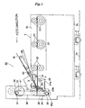
- the sheet attaching apparatus 1 mainly comprises a substrate (card body) supply station 10; an attaching station 20; a carrier strip feed station 60; and a fixing station 80.
- the substrate supply station 10, the attaching station 20 and the fixing station 80 are aligned from the right side to the left side of the figure in order.
- the card body B is fed over a feed path extending from the upstream substrate supply station 10 from the downstream fixing station 80.
- the card body B is kept on an attaching position P in the attaching station 20, at which the sheet S peeled off the carrier strip M is fed from the carrier strip feed station 60, arranged over the attaching station 20 (shown in the upper and center portion of the figure), and is adhered onto the card body B.
- the substrate supply station 10, the fixing station 80 and the carrier strip feed station 60 are stored in a main casing 2 and the attaching station 20 is stored in a movable casing 3 separated from the main casing 2 (described later in detail).
- the substrate supply station 10 is provided with a stock section 11 in which a large number of card bodies B are stacked and stored; a feed roller 13 for feeding the lowermost card body B in the stack to the attaching station 20; and the like.
- the attaching station 20, stored in the movable casing 3 described above, is mainly provided with a substrate supply unit 21 for supplying the card body B to the attaching position; a stopper 24 with which the forward edges of the card body B and the sheet S come in contact at the attaching position P, downstream of the substrate supply unit 21; a guide sheet 23 for feeding the peeled sheet S to the attaching position; an upper roller (press roller) 27 which presses the forward portion of the sheet S onto the forward portion of the card body B at the attaching position P; and a lower roller (feed roller) 28, facing the upper roller 27, for discharging the adhered sheet S and card body B from the attaching position.
- the movable casing 3 as shown in Fig.3 , has right and left side plates 3a in the feed direction and a base plate 3b on which the side plates 3a stand. A distance between the side plates 3a is slightly wider than the shorter length of the card body B. Under the base plate 3b, sliders 4 extending in the direction perpendicular to the feed direction, are mounted. The sliders 4 are slidably engaged with linier guides 5 extending in a direction perpendicular to the feed direction, mounted on a base plate 2a of the main casing 2. Thus, the movable casing 3 is movable to the main casing 2 in the direction perpendicular to the feed direction.
- the substrate supply unit 21 comprises pairs of upper and lower rollers 22 which are arranged between the side plates 3a of the movable casing 3.
- three pairs of upper and lower rollers 22 are arranged from the upstream (the right side of the figure) to the downstream (the left side of the figure).
- the card body B supplied from the substrate supply station 10, is fed by the pairs of the rollers 22 to the attaching position P at which the forward edge of the card body B contacts the stopper 24 as guided by guide plates (not shown) standing at the left and right side of the pairs of the rollers 22.
- the stopper 24 is arranged at the most downstream end of a space between the side plates 3a of the movable casing 3.
- the upstream side of the stopper 24 forms the attaching position P.
- the stopper 24 is rotatably supported to the side plate 3a at the proximal portion 24a by a pin 25 and designed so as to oscillate between a position across the feed path and a position off the feed path by an after-mentioned oscillating unit.
- the stopper 24 is biased to the position across the feed path by a spring 26 under a normal state.
- the upper roller 27 and the lower roller 28, facing the upper roller 27, are arranged.
- the upper roller is designed to move upward and downward by an after-mentioned mechanism.
- the lower roller 28 is driven by a motor. As shown in Fig.3 , in this embodiment, two pairs of upper rollers 27 and lower rollers 28 are arranged in the width direction of the card body B.
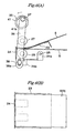
- Figs.4 are drawings showing a structure of the guide sheet
- Fig.4(A) is a plan drawing
- Fig.4(B) is a front drawing.
- the guide sheet 23 is for guiding the adhesive sheet S to the attaching position as described later and, as shown in Fig.4 , has a substantially rectangular sheet piece 23a and a mounting plate 23b for mounting the sheet piece 23a to the side plate 3a of the movable casing 3.
- the sheet piece 23b has substantially the same width as the sheet S and the length slightly shorter than the sheet S.
- the sheet piece 23a is mounted to the side plate 3a with the mounting plate 23b so as to extend obliquely downward and contact the stopper 24 with the forward edge thereof.
- the forward portion of the sheet piece 23a may be folded upward so as to be floated.
- the sheet piece 23a is made of a material to which the adhesive surface of the sheet S is hardly adhered (for example silicon resin).
- the sheet piece 23a is formed with slits 23c extending backward from the forward edge. The slits 23c are positioned under the upper rollers 27.
- the movable casing 3 is further provided with a mechanism for oscillating the stopper 24; a movable plate 50 having a mechanism for moving the upper rollers 27 upward and downward; and the like (described later in detail).
- the sheets S are arranged on the carrier strip M in rows at predetermined intervals and the carrier strip M is rolled into a roll 61 with the sheet S inward.
- One of the sheets S is supplied from the roll.
- the carrier strip feed station 60 is provided with a reel 62 on which the roll 61 is mounted and a take-up reel 63 on which the carrier strip M is wound.
- the carrier strip feed station 60 is further provided with a guide plate 65 protruding over the upstream side of the guide sheet 23.
- the guide plate 65 is fixed to the side plate of the main casing 2 so as to extend obliquely downward toward the stopper 24, as shown in Fig.1 also. Ahead of the guide plate 65, a return roller 66 for returning the carrier strip M is mounted. As shown in Fig.1 , the guide plate 65, the return roller 66 and the guide sheet 23 are aligned in the direction toward the stopper 24 in order.
- the carrier strip M supplied from the roll 61, is passed over the guide plate 65 via the guide roller 68 and is held around the return roller 66.
- the return roller 66 folds back the carrier strip M at substantially 340°.
- the sheet S adhered on the carrier strip M is not folded back and thus peeled off the carrier strip M because of its rigidity, and is fed obliquely downward with the adhesive surface down. And then, the sheet S slides on the guide sheet 23 with the adhesive surface down and then the forward edge of the sheet S comes in contact with the stopper 24.
- the carrier strip M, from which the sheet S is peeled off, is wound onto the take-up reel 63 via a guide roller 69 and a tension roller 70.
- the take-up reel 63 is driven so as to unreel the roll 61 from the reel 62.
- the fixing station 80 is for attaching the sheet S onto the card body B securely.
- the fixing station 80 is, as shown in Fig.2 , provided with upper and lower feed rollers 81; upper and lower heat rollers 82; and the like.
- the heat roller is made of heat-resistant rubber.
- the upper heat roller is rotatably supported in a heat plate 83 which covers the outer surface of the upper heat roller other than the surface facing the feed path. On heating the heat plate 83, the produced heat is translated to the heat roller and to heat it up to a predetermined temperature.
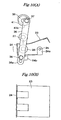
- FIGs. 5 to 10 are drawings showing the method for adhering the sheet onto the card body.
- FIG. 1 is a front drawing and each of figures (B) is a side drawing. Firstly, behaviors of the sheet and the card body will be described mainly. The driving mechanism of the stopper and the upper roller are described later.
- the card body B is fed until the forward edge of the card body b contacts the stopper 24, and then the card body B is held at the attaching position. At this time, the stopper 24 is oscillated to be across the feed path and the upper roller 27 is retracted from the feed path.
- the sheet S peeled off the carrier strip M, is fed over the guide sheet 23 until the forward edge of the sheet S contacts the stopper 24. Since the card body B keeps away from the adhesive surface of the sheet S by the guide sheet 23, the sheet S is not adhered onto the card body B. And, since the forward edges of the sheet S and the card body B contact the stopper 24, as shown in Fig.6(B) , the forward edges of the both can be aligned. If the sheet S is displaced to the card body B in the left and right directions, the movable casing 3 is moved in the direction perpendicular to the feed direction for a suitable distance to align the card body B with the sheet S.
- the upper rollers 27 are moved downward on the feed path.
- the guide sheet 23 is formed with the slits 23c
- the adhesive sheet S is not adhered onto the card body B because of the thickness of the guide sheet 23.
- the adhesive sheet S contacts the card body B, placed on the lower rollers 28, through the slits 23c of the guide sheet 23, resulting in adhesion of the adhesive sheet S and the card body B.
- the stopper 24 is oscillated to be retracted from the feed path.
- the card body B and the sheet S are discharged from the attaching position through between the upper and lower rollers 27 and 28.
- the sheet S is adhered onto the card body B at the fixing station 80 in the whole width direction whereby the whole surfaces of the card body B and the sheet S are adhered.
- the stopper 24 is oscillated to be across the feed path and the upper roller 27 is moved upward to be retracted from the feed path.
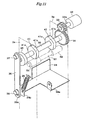
- Fig.11 is a perspective drawing showing a mechanism for oscillating the stopper.
- Figs.12 are perspective drawings showing a mechanism for moving the upper roller upward and downward, Fig.12(A) shows the upper roller positioned at the upper position and Fig.12(B) shows the upper roller positioned at the lower position.
- a rotating shaft 30 is supported between the side plates 3a of the movable casing 3.
- the rotating shaft 30 is for moving the stopper 24 and the upper roller 27.
- a back end of the rotating shaft 30 protrudes from the side plate 3a, to which a gear 31 is fixed.
- the gear 31 is engaged with a reduction gear 33 fixed to an output axis 32a of a motor 32. Driving of the motor 32 rotates the rotating shaft 30 through the reduction gear 33 and the gear 31.
- a forward end of the rotating shaft 30 protrudes from the side plate 3a, to which a roller 35 is fixed.
- the roller 35 is for oscillating the stopper 24.
- the roller 35 has a connecting rod 36 coupled thereto in such a manner that one end (upper end) of the connecting rod 36 is coupled to the end surface of the roller 35 near the circumference edge with a pin 37 (the end surface extending between the rotating shaft 30 and the pin 37 functions as a crank arm).
- Another end (lower end) of the connecting rod 36 is coupled to a work portion 24b of the stopper 24.
- the lower end of the connecting rod 36 is formed with a long hole 36a through which a pin 38, coupling the connecting rod 36 to the stopper 24, is movably inserted.
- the rotating shaft 30 is further provided with two cams 41 fixed thereto between the side plates.
- the cam 41 has a large diameter portion 41a having a circular circumference and a small diameter portion 41b having a circumference in which the radius gradually gets small from the both ends of the large diameter portion 41a toward the center.
- the cams 41 are for moving the upper roller 27 upward and downward.
- the upper roller 27 is mounted to a movable plate 50 as shown in Fig.3 and Fig.12 .
- the movable plate 50 is supported movably upward and downward between the side plates 31 of the movable casing 3.
- the movable plate 50 has a U-shaped cross section and is provided with side plates 50a from which pin 51 stands.
- Each of the pins 51 is inserted through a long hole formed at the side plate 3a of the movable casing 3 so that the movable plate 50 can be moved upward and downward along the long hole.
- the upward and downward moving of the movable plate 50 is carried out by the cams 41, causing the upward and downward moving of the upper roller 27.
- the movable plate 50 In the inactive condition, the movable plate 50 is biased upward by a spring 52 and thus the pins 51 contact the upper ends of the long holes formed at the side plate 3a of the movable casing 3.
- each side plates 50a of the movable plate 50 is formed with a lengthwise long hole 50b through which a rotating axis 53 of the upper roller 27 is inserted.
- the upper roller 27 is movably supported to the rotating axis 53.
- the rotating axis 53 has further a plate spring 54 fixed thereto. With an upper surface of the plate spring 54, a projection 55 protruding from the movable plate 50 comes in contact.
- the rotating axis 27 of the upper roller 27 contacts the lower end of the long hole 50b by its own weight and the plate spring 54 is free of load with the projection 55.
- a shaft 57 is fixed between the upper portions of the side plates 50a of the movable plate 50.
- cam followers 58 are rotatively mounted to which the cams 41 rotating contact.
- the cam follower 58 contacts the large diameter portion 41a of the cam 41, the movable plate 50 is pushed down against a spring force of the spring 52.
- the cam follower 58 contacts the small diameter portion 41b of the cam 41, the movable plate 50 is biased upward by the spring 52.
- the cam follower 58 (not shown in Fig.5 ) contacts the small diameter portion 41b of the cam 41, and thus the movable plate 50 is biased upward and the upper roller 27 is shifted to the upper position so as to be retracted from the feed path.
- the pin 37 coupling the upper end of the connecting rod 36 and the roller 35, is positioned at a position slightly lower than the uppermost point of the rotating path of the pin.
- the pin 38 coupling the stopper 24 to the connecting rod 36, is positioned at the substantially center of the long hole 36a of the connecting rod 36. So, the stopper 24 is not pushed down and advances across the feed path. Then, the card body B, fed by the substrate supply unit 21 through the upper and lower roller 27 and 28, is waiting at the attaching position at which the forward edge of the card body B contacts the stopper 24.
- the lower roller 28 is out of rotating.
- the driving timing of the lower roller 28 is controlled according to a sensor for detecting a position of the light shielding plate attached to the rotating shaft 30.
- the sheet adhering apparatus 1 can produce about 12 ID cards per one minute, for example.
Landscapes
- Engineering & Computer Science (AREA)
- Textile Engineering (AREA)
- Mechanical Engineering (AREA)
- Credit Cards Or The Like (AREA)
- Labeling Devices (AREA)
- Folding Of Thin Sheet-Like Materials, Special Discharging Devices, And Others (AREA)
Claims (4)
- Vorrichtung zum präzisen Platzieren und Aneinanderbefestigen eines von auf einem Trägerstreifen (M) in Reihen angeordneten Haftblättern (S) vorbestimmter Größe auf einem Substrat (B) umfassend:eine Substrat-Zuführstation (21) zum Zuführen des Substrats zu einer Befestigungsposition (P) entlang eines Zuführpfades;eine Trägerstreifen-Zuführstation (60) zum Zuführen des Trägerstreifens;eine Ablösestation (66) zum Ablösen des Blattes von den Trägerstreifen;einen zwischen einer Position auf dem Zuführpfad und einer Position entfernt von dem Zuführpfad beweglichen Stopper (24) welchen Vorderkanten des Substrats und des Blattes an der Befestigungsposition kontaktieren;eine Druckrolle (27); undeine der Druckrolle gegenüber angeordnete Zuführrolle zum Abführen des zusammenhaftenden Blatts und Substrats von der Befestigungsposition,dadurch gekennzeichnet, dasser weiterhin ein nicht haftendes Führungsblatt (23) zum Leiten des abgelösten Blatts an die Befestigungsposition unter Fernhalten von dem Substrat umfasst, und dadurch, dass das Führungsblatt Schlitze (23c) aufweist, die sich in der Zuführrichtung an dem Vorderabschnitt erstrecken und dadurch, dassdie Druckrolle beweglich ist und den Vorderabschnitt des Blattes auf den Vorderabschnitt des Substrats drückt, um das Blatt auf dem Substrat an der Befestigungsposition zu befestigen, und den Vorderabschnitt des Blattes auf den Vorderabschnitt des Substrats durch die Schlitze drückt, um das Blatt auf dem Substrat zu befestigen.
- Blattbefestigungsvorrichtung nach Anspruch 1,
wobei der Stopper (24) nach dem Zusammenhaften von Blatt und Substrat von dem Zuführpfad zurückgezogen wird,
die Zuführrolle (28) angetrieben wird um das zusammenhaftende Blatt und Substrat zwischen der Druckrolle und der Zuführrolle hindurch abzuführen, und
nachdem das zusammenhaftende Blatt und Substrat von der Befestigungsposition komplett abgeführt sind, die Druckrolle zurückgezogen wird und auch der Stopper über den Zuführpfad vorrückt. - Blattbefestigungsvorrichtung nach Anspruch 1 weiterhin umfassend:einen Antriebshebel und eine Nocke (41) auf einer rotierenden Welle (30);eine Verbindungsstange, die an einem Ende mit dem Antriebshebel gekoppelt ist und an dem anderen Ende mit dem Stopper (24) gekoppelt ist zum Oszillieren des Stoppers zwischen einer Position entfernt von dem Zuführpfad und einer Position auf dem Zuführpfad;eine bewegliche Platte (50) die relativ zu einem Hauptgehäuse (2) nach oben und nach unten beweglich ist und durch eine Wirkung der Nocke die Druckrolle (29) nach unten drückt, die an der nach oben und nach unten beweglichen Platte angebracht ist;eine auf der Achse der Druckrolle angebrachte Feder; undeine Hervorstehung, die von der beweglichen Platte hervorsteht und die Feder nach unten drückt.
- Blattbefestigungsvorrichtung nach Anspruch 1 weiterhin umfassend:eine Substrat-Zuführstation (10) zum Speichern des Substrats (B) und zum Zuführen eines der Substrate zu der Substrat-Zuführstation (21);wobei zwei oder mehr Stationen der Substrat-Zuführstation, der Trägerstreifen-Zuführstation (60) und der Ablösestation (66) in dem Hauptgehäuse (2) gespeichert sind,zwei oder mehr Komponenten der Substrat-Zuführstation, des Führungsblatts (23), des Stoppers (24), der Druckrolle (27) und der Zuführrolle (28) in einer Einheit (bewegliches Gehäuse 3) gespeichert sind, unddas bewegliche Gehäuse relativ zu dem Hauptgehäuse in einer Richtung senkrecht zu der Zuführrichtung beweglich ist.
Applications Claiming Priority (2)
| Application Number | Priority Date | Filing Date | Title |
|---|---|---|---|
| JP2006249349 | 2006-09-14 | ||
| PCT/JP2007/066520 WO2008032550A1 (fr) | 2006-09-14 | 2007-08-27 | dispositif de COLLAGE de feuille adhésive |
Publications (3)
| Publication Number | Publication Date |
|---|---|
| EP2067703A1 EP2067703A1 (de) | 2009-06-10 |
| EP2067703A4 EP2067703A4 (de) | 2013-08-07 |
| EP2067703B1 true EP2067703B1 (de) | 2014-10-08 |
Family
ID=39183614
Family Applications (1)
| Application Number | Title | Priority Date | Filing Date |
|---|---|---|---|
| EP07792997.4A Not-in-force EP2067703B1 (de) | 2006-09-14 | 2007-08-27 | Klebefoliebondingvorrichtung |
Country Status (4)
| Country | Link |
|---|---|
| US (1) | US8087442B2 (de) |
| EP (1) | EP2067703B1 (de) |
| JP (1) | JP4129051B2 (de) |
| WO (1) | WO2008032550A1 (de) |
Families Citing this family (5)
| Publication number | Priority date | Publication date | Assignee | Title |
|---|---|---|---|---|
| JP5241010B2 (ja) * | 2008-12-18 | 2013-07-17 | 麒麟麦酒株式会社 | タックシールラベラ用のローラ |
| DE102010038293A1 (de) * | 2010-07-22 | 2012-01-26 | Krones Aktiengesellschaft | Spannvorrichtung |
| JP6543152B2 (ja) * | 2015-09-30 | 2019-07-10 | リンテック株式会社 | シート貼付装置および貼付方法並びに接着シート原反 |
| JP6461279B2 (ja) * | 2017-05-12 | 2019-01-30 | 株式会社 ベアック | フィルム部材貼り付け装置、フィルム部材貼り付け方法及び静電気除去部材 |
| JP7391931B2 (ja) * | 2021-12-14 | 2023-12-05 | 天昇電気工業株式会社 | シール材貼付装置 |
Family Cites Families (17)
| Publication number | Priority date | Publication date | Assignee | Title |
|---|---|---|---|---|
| US3428509A (en) * | 1964-10-27 | 1969-02-18 | Roto American Corp | Labeling machine |
| JPS5159300A (ja) * | 1974-11-20 | 1976-05-24 | Tokyo Electric Co Ltd | Raberutenchakusochi |
| JPS611044Y2 (de) * | 1979-12-28 | 1986-01-14 | ||
| FR2565949B1 (fr) * | 1984-06-15 | 1986-11-21 | Nitto Electric Ind Co | Procede et appareil pour le collage d'un ruban adhesif sur un objet mince |
| US4813571A (en) * | 1986-11-14 | 1989-03-21 | Minnesota Mining And Manufacturing Company | Adjustable label dispensing device |
| US5370754A (en) * | 1991-06-27 | 1994-12-06 | Pfizer Inc. | Automatic motorless label applying system |
| US5879507A (en) * | 1992-02-21 | 1999-03-09 | Apax Corporation | Apparatus for automatically applying adhesive-backed labels to moving articles |
| US5399228A (en) * | 1992-02-21 | 1995-03-21 | Best Label Co., Inc. | Apparatus and method for automatically applying adhesive-backed labels to moving articles |
| JP3013064B2 (ja) | 1992-05-21 | 2000-02-28 | 太陽化学株式会社 | 乳酸菌生育促進剤 |
| US5785798A (en) * | 1995-09-20 | 1998-07-28 | Multivac, Inc. | Label applying apparatus |
| JP4040153B2 (ja) * | 1997-12-09 | 2008-01-30 | 株式会社サトー | ラベル貼付装置 |
| US20030121607A1 (en) * | 1998-02-24 | 2003-07-03 | Peter Davis | Surface mount assembly system with integral label feeder |
| US6273170B1 (en) * | 1999-06-02 | 2001-08-14 | Amistar Corporation | Label shuttle and clamp bar assembly for a label placement machine |
| JP2001278233A (ja) | 2000-03-30 | 2001-10-10 | Konica Corp | 粘着ラベル分離装置、粘着ラベル貼付装置および粘着ラベル貼付方法 |
| DE10340331A1 (de) * | 2003-08-29 | 2005-06-30 | Arlinghaus, Clemens | Verfahren und Vorrichtung zum Kennzeichnen eines Aktendeckels |
| JP2006168921A (ja) * | 2004-12-16 | 2006-06-29 | Kyocera Mita Corp | 後処理装置及び画像形成装置 |
| US20060249258A1 (en) * | 2005-05-06 | 2006-11-09 | Powerforward, Inc. | Continuous motion label transferring apparatus |
-
2007
- 2007-08-27 WO PCT/JP2007/066520 patent/WO2008032550A1/ja not_active Ceased
- 2007-08-27 JP JP2007557259A patent/JP4129051B2/ja not_active Expired - Fee Related
- 2007-08-27 US US12/441,065 patent/US8087442B2/en not_active Expired - Fee Related
- 2007-08-27 EP EP07792997.4A patent/EP2067703B1/de not_active Not-in-force
Also Published As
| Publication number | Publication date |
|---|---|
| US20110132547A1 (en) | 2011-06-09 |
| JP4129051B2 (ja) | 2008-07-30 |
| WO2008032550A1 (fr) | 2008-03-20 |
| US8087442B2 (en) | 2012-01-03 |
| EP2067703A4 (de) | 2013-08-07 |
| JPWO2008032550A1 (ja) | 2010-01-21 |
| EP2067703A1 (de) | 2009-06-10 |
Similar Documents
| Publication | Publication Date | Title |
|---|---|---|
| US8168033B1 (en) | Methods and devices for printing and affixing an individual label onto an item having a machine readable code thereon | |
| US7431784B2 (en) | Method and apparatus for producing data carriers equipped with an integrated transponder | |
| CN104487354B (zh) | 用来将标签应用到物件的方法和装置 | |
| US8087442B2 (en) | Adhesive sheet bonding device | |
| EP1406230A1 (de) | Label, verfahren zu seiner benützung, verfahren zum ankleben und vorrichtung dafür | |
| JP4652790B2 (ja) | Rfidラベル検品装置及び検品方法 | |
| JP2591355B2 (ja) | 剥離紙の剥離方法 | |
| US20080315997A1 (en) | Tag tape, tag tape roll, RFID circuit element cartridge, and tag label producing apparatus | |
| JP4848129B2 (ja) | ラベル貼付装置 | |
| EP2221794B1 (de) | Etikettenblatt-herstellungseinrichtung | |
| JP4563509B1 (ja) | Rfidラベル及びラベル貼付装置 | |
| JP2002134635A (ja) | Icラベルの製造装置および製造方法 | |
| JP3118924B2 (ja) | テープ貼着装置 | |
| JPH08246Y2 (ja) | 試験管ラベル自動発行貼付装置 | |
| JP6422533B1 (ja) | ラベル剥離装置、ラベル自動貼付装置、及びラベル剥離方法 | |
| JP2007217043A (ja) | Rfidラベルの角貼り装置およびその角貼り方法 | |
| JP2006515257A (ja) | 高速フォームバッファ | |
| JP2003054054A (ja) | プリンタ | |
| JP3922661B2 (ja) | ラベル貼付装置 | |
| KR20010093278A (ko) | 개인정보가 표시된 쿠폰을 제조하는 방법과 그 설비 | |
| JP4784148B2 (ja) | Icタグの配置装置、icタグ配置済シートの製造方法、被剥離体の配置装置、および被剥離体配置済シートの製造方法 | |
| JP2021142630A (ja) | 切断移載装置及びラベル製造装置並びに切断移載方法及びラベル製造方法 | |
| JP2013095499A (ja) | ラベル剥離機構、ラベル剥離機構の制御方法およびラベル印刷装置 | |
| JP2025113547A (ja) | 貼付媒体への製造情報付与方法 | |
| JP4040153B2 (ja) | ラベル貼付装置 |
Legal Events
| Date | Code | Title | Description |
|---|---|---|---|
| PUAI | Public reference made under article 153(3) epc to a published international application that has entered the european phase |
Free format text: ORIGINAL CODE: 0009012 |
|
| 17P | Request for examination filed |
Effective date: 20090407 |
|
| AK | Designated contracting states |
Kind code of ref document: A1 Designated state(s): AT BE BG CH CY CZ DE DK EE ES FI FR GB GR HU IE IS IT LI LT LU LV MC MT NL PL PT RO SE SI SK TR |
|
| AX | Request for extension of the european patent |
Extension state: AL BA HR MK RS |
|
| DAX | Request for extension of the european patent (deleted) | ||
| A4 | Supplementary search report drawn up and despatched |
Effective date: 20130710 |
|
| RIC1 | Information provided on ipc code assigned before grant |
Ipc: B65C 9/32 20060101AFI20130704BHEP |
|
| GRAP | Despatch of communication of intention to grant a patent |
Free format text: ORIGINAL CODE: EPIDOSNIGR1 |
|
| INTG | Intention to grant announced |
Effective date: 20140417 |
|
| GRAS | Grant fee paid |
Free format text: ORIGINAL CODE: EPIDOSNIGR3 |
|
| GRAA | (expected) grant |
Free format text: ORIGINAL CODE: 0009210 |
|
| RAP1 | Party data changed (applicant data changed or rights of an application transferred) |
Owner name: AI&DI CO., LTD. |
|
| AK | Designated contracting states |
Kind code of ref document: B1 Designated state(s): AT BE BG CH CY CZ DE DK EE ES FI FR GB GR HU IE IS IT LI LT LU LV MC MT NL PL PT RO SE SI SK TR |
|
| REG | Reference to a national code |
Ref country code: GB Ref legal event code: FG4D |
|
| REG | Reference to a national code |
Ref country code: CH Ref legal event code: EP Ref country code: AT Ref legal event code: REF Ref document number: 690434 Country of ref document: AT Kind code of ref document: T Effective date: 20141015 |
|
| REG | Reference to a national code |
Ref country code: IE Ref legal event code: FG4D |
|
| REG | Reference to a national code |
Ref country code: DE Ref legal event code: R096 Ref document number: 602007038839 Country of ref document: DE Effective date: 20141113 |
|
| REG | Reference to a national code |
Ref country code: NL Ref legal event code: VDEP Effective date: 20141008 |
|
| REG | Reference to a national code |
Ref country code: AT Ref legal event code: MK05 Ref document number: 690434 Country of ref document: AT Kind code of ref document: T Effective date: 20141008 |
|
| REG | Reference to a national code |
Ref country code: LT Ref legal event code: MG4D |
|
| PG25 | Lapsed in a contracting state [announced via postgrant information from national office to epo] |
Ref country code: NL Free format text: LAPSE BECAUSE OF FAILURE TO SUBMIT A TRANSLATION OF THE DESCRIPTION OR TO PAY THE FEE WITHIN THE PRESCRIBED TIME-LIMIT Effective date: 20141008 |
|
| PG25 | Lapsed in a contracting state [announced via postgrant information from national office to epo] |
Ref country code: PT Free format text: LAPSE BECAUSE OF FAILURE TO SUBMIT A TRANSLATION OF THE DESCRIPTION OR TO PAY THE FEE WITHIN THE PRESCRIBED TIME-LIMIT Effective date: 20150209 Ref country code: FI Free format text: LAPSE BECAUSE OF FAILURE TO SUBMIT A TRANSLATION OF THE DESCRIPTION OR TO PAY THE FEE WITHIN THE PRESCRIBED TIME-LIMIT Effective date: 20141008 Ref country code: IS Free format text: LAPSE BECAUSE OF FAILURE TO SUBMIT A TRANSLATION OF THE DESCRIPTION OR TO PAY THE FEE WITHIN THE PRESCRIBED TIME-LIMIT Effective date: 20150208 Ref country code: ES Free format text: LAPSE BECAUSE OF FAILURE TO SUBMIT A TRANSLATION OF THE DESCRIPTION OR TO PAY THE FEE WITHIN THE PRESCRIBED TIME-LIMIT Effective date: 20141008 Ref country code: LT Free format text: LAPSE BECAUSE OF FAILURE TO SUBMIT A TRANSLATION OF THE DESCRIPTION OR TO PAY THE FEE WITHIN THE PRESCRIBED TIME-LIMIT Effective date: 20141008 |
|
| PG25 | Lapsed in a contracting state [announced via postgrant information from national office to epo] |
Ref country code: PL Free format text: LAPSE BECAUSE OF FAILURE TO SUBMIT A TRANSLATION OF THE DESCRIPTION OR TO PAY THE FEE WITHIN THE PRESCRIBED TIME-LIMIT Effective date: 20141008 Ref country code: SE Free format text: LAPSE BECAUSE OF FAILURE TO SUBMIT A TRANSLATION OF THE DESCRIPTION OR TO PAY THE FEE WITHIN THE PRESCRIBED TIME-LIMIT Effective date: 20141008 Ref country code: GR Free format text: LAPSE BECAUSE OF FAILURE TO SUBMIT A TRANSLATION OF THE DESCRIPTION OR TO PAY THE FEE WITHIN THE PRESCRIBED TIME-LIMIT Effective date: 20150109 Ref country code: CY Free format text: LAPSE BECAUSE OF FAILURE TO SUBMIT A TRANSLATION OF THE DESCRIPTION OR TO PAY THE FEE WITHIN THE PRESCRIBED TIME-LIMIT Effective date: 20141008 Ref country code: LV Free format text: LAPSE BECAUSE OF FAILURE TO SUBMIT A TRANSLATION OF THE DESCRIPTION OR TO PAY THE FEE WITHIN THE PRESCRIBED TIME-LIMIT Effective date: 20141008 Ref country code: AT Free format text: LAPSE BECAUSE OF FAILURE TO SUBMIT A TRANSLATION OF THE DESCRIPTION OR TO PAY THE FEE WITHIN THE PRESCRIBED TIME-LIMIT Effective date: 20141008 |
|
| REG | Reference to a national code |
Ref country code: DE Ref legal event code: R097 Ref document number: 602007038839 Country of ref document: DE |
|
| PG25 | Lapsed in a contracting state [announced via postgrant information from national office to epo] |
Ref country code: CZ Free format text: LAPSE BECAUSE OF FAILURE TO SUBMIT A TRANSLATION OF THE DESCRIPTION OR TO PAY THE FEE WITHIN THE PRESCRIBED TIME-LIMIT Effective date: 20141008 Ref country code: SK Free format text: LAPSE BECAUSE OF FAILURE TO SUBMIT A TRANSLATION OF THE DESCRIPTION OR TO PAY THE FEE WITHIN THE PRESCRIBED TIME-LIMIT Effective date: 20141008 Ref country code: RO Free format text: LAPSE BECAUSE OF FAILURE TO SUBMIT A TRANSLATION OF THE DESCRIPTION OR TO PAY THE FEE WITHIN THE PRESCRIBED TIME-LIMIT Effective date: 20141008 Ref country code: DK Free format text: LAPSE BECAUSE OF FAILURE TO SUBMIT A TRANSLATION OF THE DESCRIPTION OR TO PAY THE FEE WITHIN THE PRESCRIBED TIME-LIMIT Effective date: 20141008 Ref country code: EE Free format text: LAPSE BECAUSE OF FAILURE TO SUBMIT A TRANSLATION OF THE DESCRIPTION OR TO PAY THE FEE WITHIN THE PRESCRIBED TIME-LIMIT Effective date: 20141008 |
|
| PLBE | No opposition filed within time limit |
Free format text: ORIGINAL CODE: 0009261 |
|
| STAA | Information on the status of an ep patent application or granted ep patent |
Free format text: STATUS: NO OPPOSITION FILED WITHIN TIME LIMIT |
|
| PG25 | Lapsed in a contracting state [announced via postgrant information from national office to epo] |
Ref country code: IT Free format text: LAPSE BECAUSE OF FAILURE TO SUBMIT A TRANSLATION OF THE DESCRIPTION OR TO PAY THE FEE WITHIN THE PRESCRIBED TIME-LIMIT Effective date: 20141008 |
|
| 26N | No opposition filed |
Effective date: 20150709 |
|
| PG25 | Lapsed in a contracting state [announced via postgrant information from national office to epo] |
Ref country code: SI Free format text: LAPSE BECAUSE OF FAILURE TO SUBMIT A TRANSLATION OF THE DESCRIPTION OR TO PAY THE FEE WITHIN THE PRESCRIBED TIME-LIMIT Effective date: 20141008 |
|
| PG25 | Lapsed in a contracting state [announced via postgrant information from national office to epo] |
Ref country code: LU Free format text: LAPSE BECAUSE OF FAILURE TO SUBMIT A TRANSLATION OF THE DESCRIPTION OR TO PAY THE FEE WITHIN THE PRESCRIBED TIME-LIMIT Effective date: 20150827 Ref country code: MC Free format text: LAPSE BECAUSE OF FAILURE TO SUBMIT A TRANSLATION OF THE DESCRIPTION OR TO PAY THE FEE WITHIN THE PRESCRIBED TIME-LIMIT Effective date: 20141008 |
|
| REG | Reference to a national code |
Ref country code: CH Ref legal event code: PL |
|
| PG25 | Lapsed in a contracting state [announced via postgrant information from national office to epo] |
Ref country code: LI Free format text: LAPSE BECAUSE OF NON-PAYMENT OF DUE FEES Effective date: 20150831 Ref country code: CH Free format text: LAPSE BECAUSE OF NON-PAYMENT OF DUE FEES Effective date: 20150831 |
|
| REG | Reference to a national code |
Ref country code: IE Ref legal event code: MM4A |
|
| PG25 | Lapsed in a contracting state [announced via postgrant information from national office to epo] |
Ref country code: IE Free format text: LAPSE BECAUSE OF NON-PAYMENT OF DUE FEES Effective date: 20150827 |
|
| REG | Reference to a national code |
Ref country code: FR Ref legal event code: PLFP Year of fee payment: 10 |
|
| PGFP | Annual fee paid to national office [announced via postgrant information from national office to epo] |
Ref country code: GB Payment date: 20160824 Year of fee payment: 10 |
|
| PGFP | Annual fee paid to national office [announced via postgrant information from national office to epo] |
Ref country code: FR Payment date: 20160825 Year of fee payment: 10 |
|
| PGFP | Annual fee paid to national office [announced via postgrant information from national office to epo] |
Ref country code: DE Payment date: 20161014 Year of fee payment: 10 |
|
| PG25 | Lapsed in a contracting state [announced via postgrant information from national office to epo] |
Ref country code: MT Free format text: LAPSE BECAUSE OF FAILURE TO SUBMIT A TRANSLATION OF THE DESCRIPTION OR TO PAY THE FEE WITHIN THE PRESCRIBED TIME-LIMIT Effective date: 20141008 |
|
| PG25 | Lapsed in a contracting state [announced via postgrant information from national office to epo] |
Ref country code: HU Free format text: LAPSE BECAUSE OF FAILURE TO SUBMIT A TRANSLATION OF THE DESCRIPTION OR TO PAY THE FEE WITHIN THE PRESCRIBED TIME-LIMIT; INVALID AB INITIO Effective date: 20070827 Ref country code: BG Free format text: LAPSE BECAUSE OF FAILURE TO SUBMIT A TRANSLATION OF THE DESCRIPTION OR TO PAY THE FEE WITHIN THE PRESCRIBED TIME-LIMIT Effective date: 20141008 |
|
| REG | Reference to a national code |
Ref country code: DE Ref legal event code: R082 Ref document number: 602007038839 Country of ref document: DE Representative=s name: KLUNKER IP PATENTANWAELTE PARTG MBB, DE |
|
| PG25 | Lapsed in a contracting state [announced via postgrant information from national office to epo] |
Ref country code: TR Free format text: LAPSE BECAUSE OF FAILURE TO SUBMIT A TRANSLATION OF THE DESCRIPTION OR TO PAY THE FEE WITHIN THE PRESCRIBED TIME-LIMIT Effective date: 20141008 |
|
| PG25 | Lapsed in a contracting state [announced via postgrant information from national office to epo] |
Ref country code: BE Free format text: LAPSE BECAUSE OF FAILURE TO SUBMIT A TRANSLATION OF THE DESCRIPTION OR TO PAY THE FEE WITHIN THE PRESCRIBED TIME-LIMIT Effective date: 20141008 |
|
| REG | Reference to a national code |
Ref country code: DE Ref legal event code: R119 Ref document number: 602007038839 Country of ref document: DE |
|
| GBPC | Gb: european patent ceased through non-payment of renewal fee |
Effective date: 20170827 |
|
| REG | Reference to a national code |
Ref country code: FR Ref legal event code: ST Effective date: 20180430 |
|
| PG25 | Lapsed in a contracting state [announced via postgrant information from national office to epo] |
Ref country code: GB Free format text: LAPSE BECAUSE OF NON-PAYMENT OF DUE FEES Effective date: 20170827 Ref country code: DE Free format text: LAPSE BECAUSE OF NON-PAYMENT OF DUE FEES Effective date: 20180301 |
|
| PG25 | Lapsed in a contracting state [announced via postgrant information from national office to epo] |
Ref country code: FR Free format text: LAPSE BECAUSE OF NON-PAYMENT OF DUE FEES Effective date: 20170831 |