EP2067933A2 - Sicherheitskonzept für eine Dampfturbine - Google Patents
Sicherheitskonzept für eine Dampfturbine Download PDFInfo
- Publication number
- EP2067933A2 EP2067933A2 EP07017132A EP07017132A EP2067933A2 EP 2067933 A2 EP2067933 A2 EP 2067933A2 EP 07017132 A EP07017132 A EP 07017132A EP 07017132 A EP07017132 A EP 07017132A EP 2067933 A2 EP2067933 A2 EP 2067933A2
- Authority
- EP
- European Patent Office
- Prior art keywords
- steam
- cooling
- line
- steam turbine
- valve
- Prior art date
- Legal status (The legal status is an assumption and is not a legal conclusion. Google has not performed a legal analysis and makes no representation as to the accuracy of the status listed.)
- Granted
Links
- 238000001816 cooling Methods 0.000 claims abstract description 75
- 238000000034 method Methods 0.000 claims abstract description 9
- 239000002826 coolant Substances 0.000 abstract description 16
- 241000196324 Embryophyta Species 0.000 description 8
- 235000010678 Paulownia tomentosa Nutrition 0.000 description 2
- 240000002834 Paulownia tomentosa Species 0.000 description 2
- 230000009969 flowable effect Effects 0.000 description 2
- 238000007789 sealing Methods 0.000 description 2
- 230000035882 stress Effects 0.000 description 2
- 230000001934 delay Effects 0.000 description 1
- 230000000694 effects Effects 0.000 description 1
- 230000008646 thermal stress Effects 0.000 description 1
Images

Classifications
-
- F—MECHANICAL ENGINEERING; LIGHTING; HEATING; WEAPONS; BLASTING
- F01—MACHINES OR ENGINES IN GENERAL; ENGINE PLANTS IN GENERAL; STEAM ENGINES
- F01D—NON-POSITIVE DISPLACEMENT MACHINES OR ENGINES, e.g. STEAM TURBINES
- F01D25/00—Component parts, details, or accessories, not provided for in, or of interest apart from, other groups
- F01D25/08—Cooling; Heating; Heat-insulation
- F01D25/12—Cooling
-
- F—MECHANICAL ENGINEERING; LIGHTING; HEATING; WEAPONS; BLASTING
- F01—MACHINES OR ENGINES IN GENERAL; ENGINE PLANTS IN GENERAL; STEAM ENGINES
- F01D—NON-POSITIVE DISPLACEMENT MACHINES OR ENGINES, e.g. STEAM TURBINES
- F01D25/00—Component parts, details, or accessories, not provided for in, or of interest apart from, other groups
- F01D25/24—Casings; Casing parts, e.g. diaphragms, casing fastenings
- F01D25/26—Double casings; Measures against temperature strain in casings
-
- F—MECHANICAL ENGINEERING; LIGHTING; HEATING; WEAPONS; BLASTING
- F01—MACHINES OR ENGINES IN GENERAL; ENGINE PLANTS IN GENERAL; STEAM ENGINES
- F01K—STEAM ENGINE PLANTS; STEAM ACCUMULATORS; ENGINE PLANTS NOT OTHERWISE PROVIDED FOR; ENGINES USING SPECIAL WORKING FLUIDS OR CYCLES
- F01K13/00—General layout or general methods of operation of complete plants
- F01K13/006—Auxiliaries or details not otherwise provided for
-
- F—MECHANICAL ENGINEERING; LIGHTING; HEATING; WEAPONS; BLASTING
- F05—INDEXING SCHEMES RELATING TO ENGINES OR PUMPS IN VARIOUS SUBCLASSES OF CLASSES F01-F04
- F05D—INDEXING SCHEME FOR ASPECTS RELATING TO NON-POSITIVE-DISPLACEMENT MACHINES OR ENGINES, GAS-TURBINES OR JET-PROPULSION PLANTS
- F05D2220/00—Application
- F05D2220/30—Application in turbines
- F05D2220/31—Application in turbines in steam turbines
-
- F—MECHANICAL ENGINEERING; LIGHTING; HEATING; WEAPONS; BLASTING
- F05—INDEXING SCHEMES RELATING TO ENGINES OR PUMPS IN VARIOUS SUBCLASSES OF CLASSES F01-F04
- F05D—INDEXING SCHEME FOR ASPECTS RELATING TO NON-POSITIVE-DISPLACEMENT MACHINES OR ENGINES, GAS-TURBINES OR JET-PROPULSION PLANTS
- F05D2260/00—Function
- F05D2260/20—Heat transfer, e.g. cooling
- F05D2260/232—Heat transfer, e.g. cooling characterized by the cooling medium
- F05D2260/2322—Heat transfer, e.g. cooling characterized by the cooling medium steam
Definitions
- the invention relates to a steam turbine plant, comprising a steam turbine with a flow medium flowable through a flow medium, a live steam supply for supplying live steam, arranged in the live steam supply live steam valve, a cooling steam line for supplying cooling steam to the steam turbine, wherein the steam turbine is connected to the cooling steam line the steam turbine is designed such that thermally loaded components can be wetted by the cooling steam and a cooling steam valve arranged in the cooling steam line. Furthermore, the invention relates to a method for cooling a steam turbine, wherein the steam turbine is flowed through an external cooling steam line with a cooling steam and a live steam feed with live steam.
- Steam turbines are currently flowed with live steam, which has a live steam temperature of up to 600 ° C. Higher live steam temperatures require a well-functioning cooling device. Thermally loaded components of the steam turbine must be cooled by means of a cooling medium.
- the cooling medium is fed to the steam turbine via an external cooling steam line.
- the cooling steam is taken for example from the steam generator or branched off from the main steam line before the steam valves, cooled and then fed to the steam turbine at the points that are thermally stressed and therefore must be cooled.
- the cooling medium is provided automatically via the compressor in the respective operating state of the system accordingly.
- the mass flow of the cooling steam to the steam turbine does not correlate correspondingly quickly in the event of a sudden change in the load state of the steam turbine, ie that the mass flow of the cooling steam initially remains undesirably the same after the sudden change in load.
- a fast load change would be, for example, a load shedding or a turbine short circuit.
- the initially undesirably high mass flow of the cooling steam temporarily leads to a high pressure difference between the components to be cooled in the steam turbine and an inflow space of the steam turbine.
- the separating component or the sealing elements between these spaces or the components to be cooled themselves are mechanically stressed here.
- the pressure of the cooling medium automatically drops as well.
- the thin-walled components to be cooled thereby experience no special mechanical stress.
- temporary pressure differences of several 100 bar between the cooling medium and the failed component may occur in such a case in which rapid load changes occur.
- Thin-walled cooling elements can not withstand these stresses and are damaged. Since a sudden load change can not be ruled out according to experience, safety precautions must be taken to avoid damage to the steam turbine components. It would be desirable to form such a steam turbine system with a safety system, which in case of failure of existing safety systems, such as its own quick-closing valve for the cooling medium yet provides suitable protection for mechanically manufactured cooling components.
- the invention is based, whose task is to provide a steam turbine plant, which minimizes the risk of damage to the cooling components in a sudden load shedding.
- a further object of the invention is to specify a method in which a component to be cooled or a backwashed component in a steam turbine is not damaged during load shedding.
- a steam turbine system comprising a steam turbine with a flow medium flowable through a flow channel, a live steam supply for supplying live steam, a arranged in the live steam supply live steam valve, a cooling steam line for supplying cooling steam to the steam turbine, wherein the steam turbine with the cooling steam line is connected.
- the steam turbine is designed in such a way that thermally loaded components can be flowed through with the cooling steam and a cooling steam valve arranged in the cooling steam line, wherein a transverse line fluidly connects the cooling steam line to the live steam supply, wherein a transverse line valve is arranged in the transverse line.
- the object directed to the method is achieved by a method for cooling a steam turbine, wherein the steam turbine is flowed through an external cooling steam line with an external cooling steam and is flowed through a live steam supply with live steam, wherein a transverse line with a cross-line valve between the cooling steam line and the Main steam supply is arranged, wherein the cross-line valve opens when in the live steam supply occurs suddenly occurring pressure drop.
- the invention is based on the aspect that quick-acting valves in the cooling steam line not fast enough to a sudden load change close and thereby too high a mass flow of the cooling medium is passed into the steam turbine, whereby an excessive pressure in the steam turbine, especially in the components to be cooled occurs.
- An advantage of the invention is that now between the external cooling steam line and the live steam supply a transverse line is provided, which is closed in nominal operation with a cross-line valve, so that no cooling medium flows through the transverse line to the live steam supply. In the event of a sudden load change, the quick-closing valve in the live steam supply closes, as a result of which the pressure in the live steam supply suddenly drops.
- the quick-closing valve in the cooling steam line delays in comparison with the quick-closing valve in the live steam supply, a state is present for a short time, which is undesirable, because for this short time until the quick-closing valve in the cooling steam line closes, the high mass flow in the cooling steam line too high a pressure in the components to be cooled in the steam turbine.
- the cross-line valve opens for this case and thereby the cooling steam is passed from the cooling steam line via the transverse line to the live steam supply.
- the live steam supply is dimensioned in relation to the cooling steam line in such a way that the mass flow of the cooling medium in the live steam feed leads to no damage to the steam turbine.
- the cross-line valve is designed as a spring-loaded check valve.
- the spring-loaded check valve is dimensioned such that during normal operation, the cross-line valve remains closed. In nominal operation, the pressure of the cooling medium is higher than the pressure of the live steam. In the event of a sudden load shedding, the pressure of the live steam in the live steam feed unit is abruptly reduced.
- the spring-loaded check valve must in this case are dimensioned such that in this suddenly occurring pressure difference between the pressure in the cooling steam line and the live steam supply opens the valve.
- the control of the cross-line valve is made passive, so to speak. This means that the cross-line valve does not have to be activated actively via a control unit.
- the controlled variables are now the pressures in the cooling steam line and in the live steam feed.
- any form of passive pressure relief valve that opens above a certain pressure differential can be used.
- the transverse line is viewed in the flow direction of the live steam and, seen in the flow direction of the cooling steam, is arranged behind the live steam valve and the cooling steam valve.
- the main steam valve and the cooling steam valve are usually designed as a valve combination of a quick-acting valve and a control valve.
- the quick-closing valve has the task in case of failure to close the mass flow through the cooling steam line.
- the transverse line is arranged inside the steam turbine.
- the transverse line can advantageously be arranged in the inner housing. Outside the steam turbine arranged transverse lines offer the risk of damage due to accidents outside the steam turbine. The arrangement of the transverse line in the inner housing minimizes this risk.
- a steam turbine 1 comprising an outer housing 2 and an inner housing 3 is shown.
- a rotor 4 is rotatably mounted about a rotation axis 5.
- the rotor 4 has a thrust balance piston 6 and a plurality of blades 7.
- the inner housing 3 has a plurality of guide vanes 8.
- a flow channel 9 is formed, which is equipped with the guide vanes 8 and the blades 7.
- a live steam flows via the live steam feed 10, via a quick-closing valve 11 and a control valve 12 into an inlet region 13 into the steam turbine 1.
- the live steam flows through the flow channel 9 along the guide vanes 8 and blades 7, expands to a lower pressure and cools through.
- the thermal energy of the live steam is converted into rotational energy and transmitted via the blades 7 to the rotor.
- a region subject to particular thermal stress is the area in the vicinity of the thrust balance piston 6.
- a cooling steam is conveyed via an external cooling steam line 14 via a quick closing and a control valve 15, 16 the steam turbine is led to the otherwise thermally stressed areas.
- the inner housing 3 in this case has a plurality of cooling holes 17.
- the cooling medium flows in this case in a space between the inner housing 3 and the outer housing 2 to the cooling hole 17.
- the outer housing 2 in this case has an outer housing cooling hole 19 through which the cooling steam enters the space 18.
- the transverse line 21 In the flow direction of Seen cooling steam branches off at the point 20, the transverse line 21 from.
- the transverse line 21 connects the point 20 with the point 22.
- the point 22 represents a branch from the live steam supply 10 to the transverse line 21.
- a transverse line valve 23 In the transverse line 21, a transverse line valve 23 is arranged.
- the cross-line valve 23 is in this case designed as a spring-loaded check valve, which then opens when in the live steam supply 10, the pressure drops abruptly. As a result, the cooling medium is conducted via the cooling medium line 14 and via the point 20 into the inflow region 13. Thus, a too large differential pressure load between the cooling chamber 18 and inflow 13 is avoided via the cooling hole 17, whereby a mechanical overstressing of parts of the inner housing 3 (also includes sealing elements) is avoided.
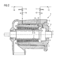
- FIG. 2 is an alternative embodiment to the steam turbine according to FIG. 1 shown.
- the transverse line 21 is not designed as an external transverse line, but as an internal transverse line 24.
- This internal transverse line 24 is disposed within the inner housing 3.
- the internal cross-line 24 also has a cross-line valve 23, which is designed as a spring-loaded check valve.
- the external transverse line 21 which avoids or reduces the risk of damaging influence on an external component.
Landscapes
- Engineering & Computer Science (AREA)
- Mechanical Engineering (AREA)
- General Engineering & Computer Science (AREA)
- Chemical & Material Sciences (AREA)
- Combustion & Propulsion (AREA)
- Control Of Turbines (AREA)
- Turbine Rotor Nozzle Sealing (AREA)
Abstract
Description
- Die Erfindung betrifft eine Dampfturbinenanlage, umfassend eine Dampfturbine mit einem mit einem Strömungsmedium beströmbaren Strömungskanal, eine Frischdampfzuführung zum Zuführen von Frischdampf, einem in der Frischdampfzuführung angeordneten Frischdampfventil, eine Kühldampfleitung zum Zuführen von Kühldampf zur Dampfturbine, wobei die Dampfturbine mit der Kühldampfleitung verbunden ist, wobei die Dampfturbine derart ausgebildet ist, das thermisch belastete Komponenten mit dem Kühldampf beströmbar sind und einem in der Kühldampfleitung angeordneten Kühldampfventil. Des Weiteren betrifft die Erfindung ein Verfahren zur Kühlung einer Dampfturbine, wobei die Dampfturbine über eine externe Kühldampfleitung mit einem Kühldampf und über eine Frischdampfzuführung mit Frischdampf beströmt wird.
- Dampfturbinen werden derzeit mit Frischdampf beströmt, der eine Frischdampftemperatur von bis zu 600°C aufweist. Höhere Frischdampftemperaturen erfordern eine gut funktionierende Kühleinrichtung. Thermisch belastete Komponenten der Dampfturbine müssen mittels eines Kühlmediums gekühlt werden. Das Kühlmedium wird der Dampfturbine über eine externe Kühldampfleitung zugeführt. Der Kühldampf wird beispielsweise aus dem Dampferzeuger entnommen oder aus der Frischdampfleitung vor den Frischdampfventilen abgezweigt, gekühlt und anschließend der Dampfturbine an den Stellen zugeführt, die thermisch belastet sind und daher gekühlt werden müssen. Bei Gasturbinen als Ausführungsform einer Strömungsmaschine wird das Kühlmedium über den Verdichter im jeweiligen Betriebszustand der Anlage entsprechend automatisch zur Verfügung gestellt. Bei Gasturbinen tritt der Effekt auf, dass bei einem geänderten Betrieb außerhalb des Nennbetriebs, beispielsweise bei einem Lastabwurf, verringerter Massenstrom an Kühldampf vorliegt. Solch ein Konzept, bei dem sich die Kühldampfmenge passiv an den Lastzustand der Anlage anpasst, ist für Dampfturbinenanlagen nicht ohne weiteres möglich. Bei einer externen Zuführung von Kühldampf zur Kühlung der Dampfturbine muss die Zuführung des Kühldampfs über mindestens ein Schnellschlussventil und mindestens ein Stellventil zugeführt werden. Der Frischdampf wird ebenfalls über ein Stell- und einem Schnellschlussventil der Dampfturbine zugeführt. In der Praxis kann es allerdings vorkommen, dass bei einem plötzlichen Eintritt einer Änderung des Lastzustandes der Dampfturbine der Massenstrom des Kühldampfs zur Dampfturbine hin nicht entsprechend schnell korreliert, d.h. dass nach der plötzlichen Laständerung der Massenstrom des Kühldampfes zunächst unerwünscht gleich groß bleibt. Eine schnelle Laständerung wäre beispielsweise ein Lastabwurf oder ein Turbinenschnellschluss. Der zunächst unerwünscht hohe Massenstrom des Kühldampfs führt allerdings temporär zu einer hohen Druckdifferenz zwischen der zu kühlenden Komponenten in der Dampfturbine und einem Einströmraum der Dampfturbine. Besonders das trennende Bauteil bzw. die Dichtelemente zwischen diesen Räumen oder die zu kühlenden Komponenten selbst werden hierbei mechanisch stark beansprucht.
- Fällt bei einer Gasturbine das Arbeitsmedium aus, so sinkt automatisch der Druck des Kühlmediums ebenfalls ab. Die dünnwandigen zu kühlenden Bauteile erfahren dadurch keine besondere mechanische Belastung. Bei der separaten Zufuhr des Kühlmediums, wie dies bei Dampfturbinen für hohe Frischdampftemperaturen der Fall sein wird, können in solch einem Fall, bei dem schnelle Laständerungen auftreten, temporäre Druckdifferenzen von mehreren 100 bar zwischen dem Kühlmedium und der ausgefallenen Komponente auftreten. Dünnwandige Kühlelemente können diesen Belastungen nicht standhalten und werden beschädigt. Da eine plötzliche Laständerung erfahrungsgemäß nicht auszuschließen ist, müssen Sicherheitsvorkehrungen getroffen werden, um eine Beschädigung der Dampfturbinenkomponenten zu vermeiden. Wünschenswert wäre es, solch eine Dampfturbinenanlage mit einem Sicherheitssystem auszubilden, das bei einem Versagen der vorhandenen Sicherheitssysteme, z.B. ein eigenes Schnellschlussventil für das Kühlmedium dennoch einen geeigneten Schutz bietet für mechanisch gefertigte Kühlkomponenten.
- An dieser Stelle setzt die Erfindung an, deren Aufgabe es ist, eine Dampfturbinenanlage anzugeben, die bei einem plötzlichen Lastabwurf die Gefahr einer Beschädigung der Kühlkomponenten minimiert. Eine weitere Aufgabe der Erfindung ist es, ein Verfahren anzugeben, bei dem eine zu kühlende bzw. eine hinterspülte Komponente in einer Dampfturbine bei einem Lastabwurf nicht beschädigt wird.
- Die auf die Vorrichtung hin gerichtete Aufgabe wird gelöst durch eine Dampfturbinenanlage umfassend eine Dampfturbine mit einem mit einem Strömungsmedium beströmbaren Strömungskanal, eine Frischdampfzuführung zum Zuführen von Frischdampf, einem in der Frischdampfzuführung angeordneten Frischdampfventil, eine Kühldampfleitung zum Zuführen von Kühldampf zur Dampfturbine, wobei die Dampfturbine mit der Kühldampfleitung verbunden ist. Wobei die Dampfturbine derart ausgebildet, dass thermisch belastete Komponenten mit dem Kühldampf beströmbar sind, und einem in der Kühldampfleitung angeordneten Kühldampfventil, wobei eine Querleitung die Kühldampfleitung mit der Frischdampfzuführung strömungstechnisch miteinander verbindet, wobei in der Querleitung ein Querleitungsventil angeordnet ist.
- Die auf das Verfahren hin gerichtete Aufgabe wird gelöst durch ein Verfahren zur Kühlung einer Dampfturbine, wobei die Dampfturbine über eine externe Kühldampfleitung mit einem externen Kühldampf beströmt wird und über eine Frischdampfzuführung mit Frischdampf beströmt wird, wobei eine Querleitung mit einem Querleitungsventil zwischen der Kühldampfleitung und der Frischdampfzuführung angeordnet wird, wobei das Querleitungsventil öffnet, wenn in der Frischdampfzuführung ein plötzlich eintretender Druckabfall auftritt.
- Die Erfindung geht von dem Aspekt aus, dass Schnellschlussventile in der Kühldampfleitung nicht schnell genug auf eine plötzliche Laständerung hin schließen und dadurch ein zu hoher Massenstrom des Kühlmediums in die Dampfturbine geleitet wird, wodurch ein zu hoher Druck in der Dampfturbine, insbesondere bei den zu kühlenden Komponenten auftritt. Ein Vorteil der Erfindung ist es, dass nunmehr zwischen der externen Kühldampfleitung und der Frischdampfzuführung eine Querleitung vorgesehen ist, die im Nennbetrieb mit einem Querleitungsventil geschlossen ist, so dass kein Kühlmedium über die Querleitung zur Frischdampfzuführung strömt. Bei einer plötzlichen Laständerung schließt das Schnellschlussventil in der Frischdampfzuführung, wodurch der Druck in der Frischdampfzuführung plötzlich abfällt. Wenn in der Kühldampfleitung das Schnellschlussventil im Vergleich zum Schnellschlussventil in der Frischdampfzuführung verzögert schließt, liegt für eine kurze Zeit ein Zustand vor, der unerwünscht ist, denn für diese kurze Zeit bis das Schnellschlussventil in der Kühldampfleitung schließt, führt der hohe Massenstrom in der Kühldampfleitung zu einem zu hohen Druck in den zu kühlenden Komponenten in der Dampfturbine. Das Querleitungsventil öffnet für diesen Fall und dadurch wird der Kühldampf von der Kühldampfleitung über die Querleitung zur Frischdampfzuführung geleitet. Die Frischdampfzuführung ist gegenüber der Kühldampfleitung derart dimensioniert, dass der Massenstrom des Kühlmediums in der Frischdampfzuführung zu keiner Beschädigung der Dampfturbine führt. Durch dieses Sicherheitskonzept, das passiv ausgeführt werden kann, ist eine zuverlässige Möglichkeit nunmehr vorgestellt, wie eine Dampfturbine zuverlässig mit einem externen Kühlmedium gekühlt werden kann.
- Vorteilhafterweise wird das Querleitungsventil als ein federbelastetes Rückschlagventil ausgebildet. Das federbelastete Rückschlagventil wird dabei derart dimensioniert, dass im Nennbetrieb das Querleitungsventil geschlossen bleibt. Im Nennbetrieb ist der Druck des Kühlmediums höher als der Druck des Frischdampfes. Bei einem plötzlichen Lastabwurf wird der Druck des Frischdampfes in der Frischdampfzuführung schlagartig geringer. Das federbelastete Rückschlagventil muss hierbei derart dimensioniert werden, dass bei diesen plötzlich auftretenden Druckunterschied zwischen dem Druck in der Kühldampfleitung und der Frischdampfzuführung das Ventil öffnet. Somit ist die Steuerung des Querleitungsventils sozusagen passiv ausgeführt. Das bedeutet, das Querleitungsventil muss nicht aktiv über eine Steuerungseinheit aktiviert werden. Als Regelgrößen dienen nunmehr die Drücke in der Kühldampfleitung und in der Frischdampfzuführung.
- Statt eines federbelasteten Rückschlagventils kann jede Form eines passiven Überdruckventils, das oberhalb einer bestimmten Druckdifferenz öffnet, verwendet werden.
- Vorteilhafterweise wird die Querleitung in Strömungsrichtung des Frischdampfes gesehen und in Strömungsrichtung des Kühldampfes gesehen hinter dem Frischdampfventil und dem Kühldampfventil angeordnet. Das Frischdampfventil und das Kühldampfventil werden üblicherweise als eine Ventilkombination aus einem Schnellschlussventil und einem Stellventil ausgeführt. Das Schnellschlussventil hat die Aufgabe bei einer Störung den Massenstrom durch die Kühldampfleitung zu schließen.
- In einer vorteilhaften Weiterbildung ist die Querleitung innerhalb der Dampfturbine angeordnet. Dadurch lässt sich eine Dampfturbinenanlage herstellen, die ohne eine Querleitung aus beispielsweise Rohren besteht. Die Querleitung kann vorteilhafterweise im Innengehäuse angeordnet sein. Außerhalb der Dampfturbine angeordnete Querleitungen bieten die Gefahr einer Beschädigung durch Unfälle außerhalb der Dampfturbine. Durch die Anordnung der Querleitung im Innengehäuse ist diese Gefahr minimiert. Die Vorteile der auf das Verfahren hin gerichteten Lösung entsprechen den Vorteilen der zur Dampfturbinenanlage besprochenen Lösung.
- Im Folgenden wird ein Ausführungsbeispiel anhand von Figuren näher erläutert. Dabei haben Komponenten mit gleicher Funktionsweise gleiche Bezugszeichen.
- Es zeigen:
- FIG 1
- eine Dampfturbinenanlage mit einer externen Querlei- tung,
- FIG 2
- eine Dampfturbinenanlage mit einer internen Querlei- tung.
- In der
FIG 1 ist eine Dampfturbine 1 umfassend ein Außengehäuse 2 und ein Innengehäuse 3 dargestellt. Innerhalb des Innengehäuses 3 ist ein Rotor 4 um eine Rotationsachse 5 drehbar gelagert. Der Rotor 4 weist einen Schubausgleichskolben 6 und mehrere Laufschaufeln 7 auf. Das Innengehäuse 3 weist mehrere Leitschaufeln 8 auf. Zwischen dem Rotor 4 und dem Innengehäuse 3 ist ein Strömungskanal 9 ausgebildet, der mit den Leitschaufeln 8 und den Laufschaufeln 7 bestückt ist. Im Betrieb strömt ein Frischdampf über die Frischdampfzuführung 10, über ein Schnellschlussventil 11 und einem Stellventil 12 in einen Einströmbereich 13 in die Dampfturbine 1. Der Frischdampf strömt durch den Strömungskanal 9 an den Leitschaufeln 8 und Laufschaufeln 7 entlang, expandiert auf einen niedrigeren Druck und kühlt dadurch ab. Die thermische Energie des Frischdampfes wird dabei in Rotationsenergie umgewandelt und über die Laufschaufeln 7 auf den Rotor übertragen. Ein thermisch besonders belasteter Bereich ist der Bereich in der Nähe des Schubausgleichskolbens 6. Zur Kühlung dieses Bereichs und des Raumes zwischen Innengehäuse 3 und Außengehäuse 2 ist vorgesehen, dass ein Kühldampf über eine externe Kühldampfleitung 14 über ein Schnellschluss- und ein Stellventil 15, 16 in die Dampfturbine zu den ansonsten thermisch belasteten Bereichen geführt wird. Das Innengehäuse 3 weist hierbei mehrere Kühlbohrungen 17 auf. Das Kühlmedium strömt hierbei in einem Raum zwischen dem Innengehäuse 3 und dem Außengehäuse 2 zur Kühlbohrung 17. Das Außengehäuse 2 weist hierbei eine Außengehäusekühlbohrung 19 auf, durch den der Kühldampf in den Raum 18 gelangt. In Strömungsrichtung des Kühldampfes gesehen zweigt an der Stelle 20 die Querleitung 21 ab. Die Querleitung 21 verbindet die Stelle 20 mit der Stelle 22. Die Stelle 22 stellt eine Abzweigung dar von der Frischdampfzuführung 10 zur Querleitung 21. In der Querleitung 21 ist ein Querleitungsventil 23 angeordnet. - Das Querleitungsventil 23 ist hierbei als ein federbelastetes Rückschlagventil ausgebildet, das dann öffnet, wenn in der Frischdampfzuführung 10 der Druck schlagartig abfällt. Dadurch wird das Kühlmedium über die Kühlmediumleitung 14 und über die Stelle 20 in den Einströmbereich 13 geführt. Somit wird über die Kühlbohrung 17 eine zu große Differenzdruckbelastung zwischen Kühlraum 18 und Einströmbereich 13 vermieden, wodurch eine mechanische Überbeanspruchung von Teilen des Innengehäuses 3 (beinhaltet auch Dichtelemente) vermieden wird.
- In der
FIG 2 ist eine alternative Ausführungsform zu der Dampfturbine gemäßFIG 1 dargestellt. Der Unterschied zu der Ausführungsform gemäßFIG 1 besteht darin, dass die Querleitung 21 nicht als eine externe Querleitung ausgeführt ist, sondern als eine interne Querleitung 24. Diese interne Querleitung 24 ist innerhalb des Innengehäuses 3 angeordnet. Die interne Querleitung 24 weist ebenfalls ein Querleitungsventil 23 auf, das als ein federbelastetes Rückschlagventil ausgebildet ist. Somit entfällt in derFIG 2 die externe Querleitung 21, wodurch ein Gefahrenpotenzial durch schädigenden Einfluss auf eine externe Komponente vermieden bzw. vermindert ist.
Claims (9)
- Dampfturbinenanlage,
umfassend eine Dampfturbine (1) mit einem mit einem Strömungsmedium beströmbaren Strömungskanal (9),
eine Frischdampfzuführung (10) zum Zuführen von Frischdampf,
einem in der Frischdampfzuführung (10) angeordneten Frischdampfventil (11, 12),
eine Kühldampfleitung (14) zum Zuführen von Kühldampf zur Dampfturbine (1),
wobei die Dampfturbine (1) mit der Kühldampfleitung (14) verbunden ist,
wobei die Dampfturbine (1) derart ausgebildet ist, dass thermisch belastete Komponenten mit dem Kühldampf beströmbar sind, und
einem in der Kühldampfleitung (14) angeordnetes Kühldampfventil (15, 16),
dadurch gekennzeichnet, dass
eine Querleitung (21) die Kühldampfleitung (14) mit der Frischdampfzuführung (10) strömungstechnisch miteinander verbindet,
wobei in der Querleitung (21) ein Querleitungsventil (23) angeordnet ist. - Dampfturbinenanlage nach Anspruch 1,
wobei das Querleitungsventil (23) als ein federbelastetes Rückschlagventil ausgebildet ist. - Dampfturbinenanlage nach Anspruch 1 oder 2,
wobei die Querleitung (21) in Strömungsrichtung des Kühldampfes gesehen hinter dem Frischdampfventil (11, 12) und dem Kühldampfventil (15, 16) angeordnet ist. - Dampfturbinenanlage nach einem der vorhergehenden Ansprüche,
wobei das Querleitungsventil (23) derart ausgebildet ist, dass
ein Druckabfall in der Frischdampfzuführung (10) zum Öffnen führt. - Dampfturbinenanlage nach einem der vorhergehenden Ansprüche,
wobei die Querleitung (21) innerhalb der Dampfturbine (1) angeordnet ist. - Dampfturbinenanlage nach Anspruch 5,
wobei die Dampfturbine (1) ein Außengehäuse (2) und ein Innengehäuse (3) aufweist und die Querleitung (21) im Innengehäuse (3) angeordnet ist. - Verfahren zur Kühlung einer Dampfturbine (1),
wobei die Dampfturbine (1) über eine externe Kühldampfleitung (14) mit einem externen Kühldampf beströmt wird und über eine Frischdampfzuführung (10) mit Frischdampf beströmt wird,
dadurch gekennzeichnet, dass
eine Querleitung (21) mit einem Querleitungsventil (23) zwischen der Kühldampfleitung (14) und der Frischdampfzuführung (10) angeordnet wird,
wobei das Querleitungsventil (23) öffnet, wenn in der Frischdampfzuführung (10) ein plötzlich einsetzender Druckabfall auftritt. - Verfahren nach Anspruch 7,
wobei der Kühldampf mit einem Druck oberhalb dem Druck des Frischdampfes betrieben wird. - Verfahren nach Anspruch 7 oder 8,
wobei das Querleitungsventil (23) als ein federbelastetes Rückschlagventil ausgebildet wird.
Priority Applications (2)
| Application Number | Priority Date | Filing Date | Title |
|---|---|---|---|
| AT07017132T ATE533922T1 (de) | 2007-08-31 | 2007-08-31 | Sicherheitskonzept für eine dampfturbine |
| EP07017132A EP2067933B1 (de) | 2007-08-31 | 2007-08-31 | Sicherheitskonzept für eine Dampfturbine |
Applications Claiming Priority (1)
| Application Number | Priority Date | Filing Date | Title |
|---|---|---|---|
| EP07017132A EP2067933B1 (de) | 2007-08-31 | 2007-08-31 | Sicherheitskonzept für eine Dampfturbine |
Publications (3)
| Publication Number | Publication Date |
|---|---|
| EP2067933A2 true EP2067933A2 (de) | 2009-06-10 |
| EP2067933A3 EP2067933A3 (de) | 2011-01-05 |
| EP2067933B1 EP2067933B1 (de) | 2011-11-16 |
Family
ID=40577782
Family Applications (1)
| Application Number | Title | Priority Date | Filing Date |
|---|---|---|---|
| EP07017132A Not-in-force EP2067933B1 (de) | 2007-08-31 | 2007-08-31 | Sicherheitskonzept für eine Dampfturbine |
Country Status (2)
| Country | Link |
|---|---|
| EP (1) | EP2067933B1 (de) |
| AT (1) | ATE533922T1 (de) |
Cited By (5)
| Publication number | Priority date | Publication date | Assignee | Title |
|---|---|---|---|---|
| EP2412937A1 (de) | 2010-07-30 | 2012-02-01 | Siemens Aktiengesellschaft | Dampfturbine sowie Verfahren zum Kühlen einer solchen |
| EP2565401A1 (de) * | 2011-09-05 | 2013-03-06 | Siemens Aktiengesellschaft | Verfahren zur Temperaturausgleichung in einer Dampfturbine |
| EP2518277A4 (de) * | 2009-12-21 | 2017-04-19 | Mitsubishi Hitachi Power Systems, Ltd. | Kühlverfahren und -vorrichtung in einer einzelflussturbine |
| CN109826675A (zh) * | 2019-03-21 | 2019-05-31 | 上海电气电站设备有限公司 | 汽轮机冷却系统及方法 |
| CN114508393A (zh) * | 2021-12-27 | 2022-05-17 | 东方电气集团东方汽轮机有限公司 | 甩负荷时轴向推力为零的汽缸、一次及二次再热汽轮机 |
Families Citing this family (1)
| Publication number | Priority date | Publication date | Assignee | Title |
|---|---|---|---|---|
| CN106194284B (zh) * | 2016-07-22 | 2017-07-28 | 东方电气集团东方汽轮机有限公司 | 一种汽轮机夹层蒸汽参数调整及运行的方法 |
Family Cites Families (3)
| Publication number | Priority date | Publication date | Assignee | Title |
|---|---|---|---|---|
| DE1034193B (de) * | 1957-10-26 | 1958-07-17 | Escher Wyss Gmbh | Verfahren zum Kuehlhalten hochbeanspruchter Teile von Dampf- oder Gasturbinen |
| JPS58140408A (ja) * | 1982-02-17 | 1983-08-20 | Hitachi Ltd | 蒸気タ−ビンの冷却装置 |
| EP1674669A1 (de) * | 2004-12-21 | 2006-06-28 | Siemens Aktiengesellschaft | Verfahren zur Kühlung einer Dampfturbine |
-
2007
- 2007-08-31 AT AT07017132T patent/ATE533922T1/de active
- 2007-08-31 EP EP07017132A patent/EP2067933B1/de not_active Not-in-force
Non-Patent Citations (1)
| Title |
|---|
| None |
Cited By (14)
| Publication number | Priority date | Publication date | Assignee | Title |
|---|---|---|---|---|
| EP2518277A4 (de) * | 2009-12-21 | 2017-04-19 | Mitsubishi Hitachi Power Systems, Ltd. | Kühlverfahren und -vorrichtung in einer einzelflussturbine |
| JP2013531182A (ja) * | 2010-07-30 | 2013-08-01 | シーメンス アクティエンゲゼルシャフト | 蒸気タービンおよび該蒸気タービンの冷却法 |
| WO2012013531A1 (de) | 2010-07-30 | 2012-02-02 | Siemens Aktiengesellschaft | Dampfturbine sowie verfahren zum kühlen einer solchen |
| EP2412937A1 (de) | 2010-07-30 | 2012-02-01 | Siemens Aktiengesellschaft | Dampfturbine sowie Verfahren zum Kühlen einer solchen |
| CN103052768A (zh) * | 2010-07-30 | 2013-04-17 | 西门子公司 | 蒸汽轮机以及用于冷却这种蒸汽轮机的方法 |
| CN103764956A (zh) * | 2011-09-05 | 2014-04-30 | 西门子公司 | 用于在蒸汽轮机中进行温度补偿的方法 |
| WO2013034377A1 (de) * | 2011-09-05 | 2013-03-14 | Siemens Aktiengesellschaft | Verfahren zur temperaturausgleichung in einer dampfturbine |
| JP2015148232A (ja) * | 2011-09-05 | 2015-08-20 | シーメンス アクティエンゲゼルシャフト | 蒸気タービンの温度補償のための方法 |
| CN103764956B (zh) * | 2011-09-05 | 2015-11-25 | 西门子公司 | 用于在蒸汽轮机中进行温度补偿的方法 |
| US9416684B2 (en) | 2011-09-05 | 2016-08-16 | Siemens Aktiengesellschaft | Method for a temperature compensation in a steam turbine |
| EP2565401A1 (de) * | 2011-09-05 | 2013-03-06 | Siemens Aktiengesellschaft | Verfahren zur Temperaturausgleichung in einer Dampfturbine |
| CN109826675A (zh) * | 2019-03-21 | 2019-05-31 | 上海电气电站设备有限公司 | 汽轮机冷却系统及方法 |
| CN114508393A (zh) * | 2021-12-27 | 2022-05-17 | 东方电气集团东方汽轮机有限公司 | 甩负荷时轴向推力为零的汽缸、一次及二次再热汽轮机 |
| CN114508393B (zh) * | 2021-12-27 | 2023-07-18 | 东方电气集团东方汽轮机有限公司 | 甩负荷时轴向推力为零的汽缸、一次及二次再热汽轮机 |
Also Published As
| Publication number | Publication date |
|---|---|
| ATE533922T1 (de) | 2011-12-15 |
| EP2067933B1 (de) | 2011-11-16 |
| EP2067933A3 (de) | 2011-01-05 |
Similar Documents
| Publication | Publication Date | Title |
|---|---|---|
| DE69832740T2 (de) | Gasturbinenanlage | |
| EP1774140B1 (de) | Dampfturbine und verfahren zum betrieb einer dampfturbine | |
| EP2067933B1 (de) | Sicherheitskonzept für eine Dampfturbine | |
| DE102008029941B4 (de) | Dampfkraftanlage und Verfahren zur Regelung der Leistung einer Dampfkraftanlage | |
| DE10236294A1 (de) | Gasversorgungskontrolleinrichtung einer Gasspeicherkraftanlage | |
| CH703587A2 (de) | Druckbetätigter Stopfen. | |
| EP2596213B1 (de) | Dampfturbine mit einer internen kühlung | |
| EP0696336A1 (de) | Dichtungsanordnung für eine durchführung einer welle durch ein gehäuse sowie verfahren zu ihrem betrieb | |
| WO1998013588A1 (de) | Dampfturbine, dampfturbinenanlage sowie verfahren zur abkühlung einer dampfturbine | |
| EP1998014A2 (de) | Verfahren zum Betreiben einer mehrstufigen Dampfturbine | |
| EP3155226B1 (de) | Dampfturbine und verfahren zum betrieb einer dampfturbine | |
| EP1957759B1 (de) | Verfahren zum starten einer dampfturbinenanlage | |
| EP1455066B1 (de) | Verfahren zur Kühlung einer Strömungsmaschine und Strömungsmaschine dafür | |
| EP2288793A2 (de) | Dampfturbinensystem für ein kraftwerk | |
| EP2598724B1 (de) | Dampfturbine sowie verfahren zum kühlen einer solchen | |
| WO2016206974A1 (de) | Verfahren zum abkühlen einer strömungsmaschine | |
| EP3129623B1 (de) | Gasturbinenanlage mit vorrichtung zum spülen und/oder sperren wenigstens eines brenners und verfahren zum spülen und/oder sperren wenigstens eines brenners einer derartigen gasturbinenanlage | |
| DE2550059C2 (de) | Sicherheitssystem für eine Dampfturbinenanlage | |
| EP2724006B1 (de) | Luftturbinenanlage und zugehörige verfahren | |
| EP2031190B1 (de) | Dampfturbine mit geregelter Kühlmittelzuführung | |
| EP3183426B1 (de) | Kontrollierte kühlung von turbinenwellen | |
| EP3109420A1 (de) | Verfahren zum abkühlen einer strömungsmaschine | |
| EP3591175A1 (de) | Ausgangöffnung einer dampfturbine | |
| EP3628922A1 (de) | Verfahren zur konditionierung einer niederdruckteilturbine | |
| EP2877699A1 (de) | Niederdruck-turbine |
Legal Events
| Date | Code | Title | Description |
|---|---|---|---|
| PUAI | Public reference made under article 153(3) epc to a published international application that has entered the european phase |
Free format text: ORIGINAL CODE: 0009012 |
|
| AK | Designated contracting states |
Kind code of ref document: A2 Designated state(s): AT BE BG CH CY CZ DE DK EE ES FI FR GB GR HU IE IS IT LI LT LU LV MC MT NL PL PT RO SE SI SK TR |
|
| AX | Request for extension of the european patent |
Extension state: AL BA HR MK RS |
|
| PUAL | Search report despatched |
Free format text: ORIGINAL CODE: 0009013 |
|
| AK | Designated contracting states |
Kind code of ref document: A3 Designated state(s): AT BE BG CH CY CZ DE DK EE ES FI FR GB GR HU IE IS IT LI LT LU LV MC MT NL PL PT RO SE SI SK TR |
|
| AX | Request for extension of the european patent |
Extension state: AL BA HR MK RS |
|
| RIC1 | Information provided on ipc code assigned before grant |
Ipc: F01K 13/00 20060101ALI20101130BHEP Ipc: F01D 25/12 20060101AFI20090504BHEP |
|
| 17P | Request for examination filed |
Effective date: 20110207 |
|
| GRAP | Despatch of communication of intention to grant a patent |
Free format text: ORIGINAL CODE: EPIDOSNIGR1 |
|
| RIC1 | Information provided on ipc code assigned before grant |
Ipc: F01K 13/00 20060101ALI20110503BHEP Ipc: F01D 25/12 20060101AFI20110503BHEP |
|
| AKX | Designation fees paid |
Designated state(s): AT BE BG CH CY CZ DE DK EE ES FI FR GB GR HU IE IS IT LI LT LU LV MC MT NL PL PT RO SE SI SK TR |
|
| GRAS | Grant fee paid |
Free format text: ORIGINAL CODE: EPIDOSNIGR3 |
|
| GRAA | (expected) grant |
Free format text: ORIGINAL CODE: 0009210 |
|
| AK | Designated contracting states |
Kind code of ref document: B1 Designated state(s): AT BE BG CH CY CZ DE DK EE ES FI FR GB GR HU IE IS IT LI LT LU LV MC MT NL PL PT RO SE SI SK TR |
|
| REG | Reference to a national code |
Ref country code: GB Ref legal event code: FG4D Free format text: NOT ENGLISH |
|
| REG | Reference to a national code |
Ref country code: CH Ref legal event code: EP |
|
| REG | Reference to a national code |
Ref country code: IE Ref legal event code: FG4D Free format text: LANGUAGE OF EP DOCUMENT: GERMAN |
|
| REG | Reference to a national code |
Ref country code: CH Ref legal event code: NV Representative=s name: SIEMENS SCHWEIZ AG |
|
| REG | Reference to a national code |
Ref country code: NL Ref legal event code: VDEP Effective date: 20111116 |
|
| REG | Reference to a national code |
Ref country code: DE Ref legal event code: R096 Ref document number: 502007008668 Country of ref document: DE Effective date: 20120301 |
|
| LTIE | Lt: invalidation of european patent or patent extension |
Effective date: 20111116 |
|
| PG25 | Lapsed in a contracting state [announced via postgrant information from national office to epo] |
Ref country code: LT Free format text: LAPSE BECAUSE OF FAILURE TO SUBMIT A TRANSLATION OF THE DESCRIPTION OR TO PAY THE FEE WITHIN THE PRESCRIBED TIME-LIMIT Effective date: 20111116 Ref country code: IS Free format text: LAPSE BECAUSE OF FAILURE TO SUBMIT A TRANSLATION OF THE DESCRIPTION OR TO PAY THE FEE WITHIN THE PRESCRIBED TIME-LIMIT Effective date: 20120316 |
|
| PG25 | Lapsed in a contracting state [announced via postgrant information from national office to epo] |
Ref country code: LV Free format text: LAPSE BECAUSE OF FAILURE TO SUBMIT A TRANSLATION OF THE DESCRIPTION OR TO PAY THE FEE WITHIN THE PRESCRIBED TIME-LIMIT Effective date: 20111116 Ref country code: SI Free format text: LAPSE BECAUSE OF FAILURE TO SUBMIT A TRANSLATION OF THE DESCRIPTION OR TO PAY THE FEE WITHIN THE PRESCRIBED TIME-LIMIT Effective date: 20111116 Ref country code: NL Free format text: LAPSE BECAUSE OF FAILURE TO SUBMIT A TRANSLATION OF THE DESCRIPTION OR TO PAY THE FEE WITHIN THE PRESCRIBED TIME-LIMIT Effective date: 20111116 Ref country code: SE Free format text: LAPSE BECAUSE OF FAILURE TO SUBMIT A TRANSLATION OF THE DESCRIPTION OR TO PAY THE FEE WITHIN THE PRESCRIBED TIME-LIMIT Effective date: 20111116 Ref country code: GR Free format text: LAPSE BECAUSE OF FAILURE TO SUBMIT A TRANSLATION OF THE DESCRIPTION OR TO PAY THE FEE WITHIN THE PRESCRIBED TIME-LIMIT Effective date: 20120217 Ref country code: PL Free format text: LAPSE BECAUSE OF FAILURE TO SUBMIT A TRANSLATION OF THE DESCRIPTION OR TO PAY THE FEE WITHIN THE PRESCRIBED TIME-LIMIT Effective date: 20111116 Ref country code: PT Free format text: LAPSE BECAUSE OF FAILURE TO SUBMIT A TRANSLATION OF THE DESCRIPTION OR TO PAY THE FEE WITHIN THE PRESCRIBED TIME-LIMIT Effective date: 20120316 |
|
| REG | Reference to a national code |
Ref country code: IE Ref legal event code: FD4D |
|
| PG25 | Lapsed in a contracting state [announced via postgrant information from national office to epo] |
Ref country code: CY Free format text: LAPSE BECAUSE OF FAILURE TO SUBMIT A TRANSLATION OF THE DESCRIPTION OR TO PAY THE FEE WITHIN THE PRESCRIBED TIME-LIMIT Effective date: 20111116 |
|
| PG25 | Lapsed in a contracting state [announced via postgrant information from national office to epo] |
Ref country code: CZ Free format text: LAPSE BECAUSE OF FAILURE TO SUBMIT A TRANSLATION OF THE DESCRIPTION OR TO PAY THE FEE WITHIN THE PRESCRIBED TIME-LIMIT Effective date: 20111116 Ref country code: IE Free format text: LAPSE BECAUSE OF FAILURE TO SUBMIT A TRANSLATION OF THE DESCRIPTION OR TO PAY THE FEE WITHIN THE PRESCRIBED TIME-LIMIT Effective date: 20111116 Ref country code: SK Free format text: LAPSE BECAUSE OF FAILURE TO SUBMIT A TRANSLATION OF THE DESCRIPTION OR TO PAY THE FEE WITHIN THE PRESCRIBED TIME-LIMIT Effective date: 20111116 Ref country code: DK Free format text: LAPSE BECAUSE OF FAILURE TO SUBMIT A TRANSLATION OF THE DESCRIPTION OR TO PAY THE FEE WITHIN THE PRESCRIBED TIME-LIMIT Effective date: 20111116 Ref country code: EE Free format text: LAPSE BECAUSE OF FAILURE TO SUBMIT A TRANSLATION OF THE DESCRIPTION OR TO PAY THE FEE WITHIN THE PRESCRIBED TIME-LIMIT Effective date: 20111116 Ref country code: BG Free format text: LAPSE BECAUSE OF FAILURE TO SUBMIT A TRANSLATION OF THE DESCRIPTION OR TO PAY THE FEE WITHIN THE PRESCRIBED TIME-LIMIT Effective date: 20120216 |
|
| PG25 | Lapsed in a contracting state [announced via postgrant information from national office to epo] |
Ref country code: RO Free format text: LAPSE BECAUSE OF FAILURE TO SUBMIT A TRANSLATION OF THE DESCRIPTION OR TO PAY THE FEE WITHIN THE PRESCRIBED TIME-LIMIT Effective date: 20111116 |
|
| PLBE | No opposition filed within time limit |
Free format text: ORIGINAL CODE: 0009261 |
|
| STAA | Information on the status of an ep patent application or granted ep patent |
Free format text: STATUS: NO OPPOSITION FILED WITHIN TIME LIMIT |
|
| 26N | No opposition filed |
Effective date: 20120817 |
|
| REG | Reference to a national code |
Ref country code: DE Ref legal event code: R097 Ref document number: 502007008668 Country of ref document: DE Effective date: 20120817 |
|
| BERE | Be: lapsed |
Owner name: SIEMENS A.G. Effective date: 20120831 |
|
| PG25 | Lapsed in a contracting state [announced via postgrant information from national office to epo] |
Ref country code: MC Free format text: LAPSE BECAUSE OF NON-PAYMENT OF DUE FEES Effective date: 20120831 |
|
| PG25 | Lapsed in a contracting state [announced via postgrant information from national office to epo] |
Ref country code: ES Free format text: LAPSE BECAUSE OF FAILURE TO SUBMIT A TRANSLATION OF THE DESCRIPTION OR TO PAY THE FEE WITHIN THE PRESCRIBED TIME-LIMIT Effective date: 20120227 |
|
| PG25 | Lapsed in a contracting state [announced via postgrant information from national office to epo] |
Ref country code: BE Free format text: LAPSE BECAUSE OF NON-PAYMENT OF DUE FEES Effective date: 20120831 |
|
| PG25 | Lapsed in a contracting state [announced via postgrant information from national office to epo] |
Ref country code: FI Free format text: LAPSE BECAUSE OF FAILURE TO SUBMIT A TRANSLATION OF THE DESCRIPTION OR TO PAY THE FEE WITHIN THE PRESCRIBED TIME-LIMIT Effective date: 20111116 |
|
| REG | Reference to a national code |
Ref country code: AT Ref legal event code: MM01 Ref document number: 533922 Country of ref document: AT Kind code of ref document: T Effective date: 20120831 |
|
| PG25 | Lapsed in a contracting state [announced via postgrant information from national office to epo] |
Ref country code: AT Free format text: LAPSE BECAUSE OF NON-PAYMENT OF DUE FEES Effective date: 20120831 |
|
| PG25 | Lapsed in a contracting state [announced via postgrant information from national office to epo] |
Ref country code: MT Free format text: LAPSE BECAUSE OF FAILURE TO SUBMIT A TRANSLATION OF THE DESCRIPTION OR TO PAY THE FEE WITHIN THE PRESCRIBED TIME-LIMIT Effective date: 20111116 |
|
| PG25 | Lapsed in a contracting state [announced via postgrant information from national office to epo] |
Ref country code: TR Free format text: LAPSE BECAUSE OF FAILURE TO SUBMIT A TRANSLATION OF THE DESCRIPTION OR TO PAY THE FEE WITHIN THE PRESCRIBED TIME-LIMIT Effective date: 20111116 |
|
| PG25 | Lapsed in a contracting state [announced via postgrant information from national office to epo] |
Ref country code: LU Free format text: LAPSE BECAUSE OF NON-PAYMENT OF DUE FEES Effective date: 20120831 |
|
| PG25 | Lapsed in a contracting state [announced via postgrant information from national office to epo] |
Ref country code: HU Free format text: LAPSE BECAUSE OF FAILURE TO SUBMIT A TRANSLATION OF THE DESCRIPTION OR TO PAY THE FEE WITHIN THE PRESCRIBED TIME-LIMIT Effective date: 20070831 |
|
| REG | Reference to a national code |
Ref country code: FR Ref legal event code: PLFP Year of fee payment: 10 |
|
| PGFP | Annual fee paid to national office [announced via postgrant information from national office to epo] |
Ref country code: GB Payment date: 20160811 Year of fee payment: 10 Ref country code: IT Payment date: 20160830 Year of fee payment: 10 |
|
| PGFP | Annual fee paid to national office [announced via postgrant information from national office to epo] |
Ref country code: FR Payment date: 20160823 Year of fee payment: 10 |
|
| PGFP | Annual fee paid to national office [announced via postgrant information from national office to epo] |
Ref country code: CH Payment date: 20161109 Year of fee payment: 10 Ref country code: DE Payment date: 20161020 Year of fee payment: 10 |
|
| REG | Reference to a national code |
Ref country code: CH Ref legal event code: PCOW Free format text: NEW ADDRESS: WERNER-VON-SIEMENS-STRASSE 1, 80333 MUENCHEN (DE) |
|
| REG | Reference to a national code |
Ref country code: DE Ref legal event code: R119 Ref document number: 502007008668 Country of ref document: DE |
|
| REG | Reference to a national code |
Ref country code: CH Ref legal event code: PL |
|
| GBPC | Gb: european patent ceased through non-payment of renewal fee |
Effective date: 20170831 |
|
| PG25 | Lapsed in a contracting state [announced via postgrant information from national office to epo] |
Ref country code: CH Free format text: LAPSE BECAUSE OF NON-PAYMENT OF DUE FEES Effective date: 20170831 Ref country code: LI Free format text: LAPSE BECAUSE OF NON-PAYMENT OF DUE FEES Effective date: 20170831 |
|
| REG | Reference to a national code |
Ref country code: FR Ref legal event code: ST Effective date: 20180430 |
|
| PG25 | Lapsed in a contracting state [announced via postgrant information from national office to epo] |
Ref country code: DE Free format text: LAPSE BECAUSE OF NON-PAYMENT OF DUE FEES Effective date: 20180301 Ref country code: GB Free format text: LAPSE BECAUSE OF NON-PAYMENT OF DUE FEES Effective date: 20170831 |
|
| PG25 | Lapsed in a contracting state [announced via postgrant information from national office to epo] |
Ref country code: FR Free format text: LAPSE BECAUSE OF NON-PAYMENT OF DUE FEES Effective date: 20170831 Ref country code: IT Free format text: LAPSE BECAUSE OF NON-PAYMENT OF DUE FEES Effective date: 20170831 |