EP2067940B2 - Procédé de fonctionnement d'ne centrale à cycle combiné, et centrale à cycle combiné pour la mise en oeuvre dudit procédé - Google Patents
Procédé de fonctionnement d'ne centrale à cycle combiné, et centrale à cycle combiné pour la mise en oeuvre dudit procédé Download PDFInfo
- Publication number
- EP2067940B2 EP2067940B2 EP08162627.7A EP08162627A EP2067940B2 EP 2067940 B2 EP2067940 B2 EP 2067940B2 EP 08162627 A EP08162627 A EP 08162627A EP 2067940 B2 EP2067940 B2 EP 2067940B2
- Authority
- EP
- European Patent Office
- Prior art keywords
- feed water
- steam generator
- waste heat
- steam
- power plant
- Prior art date
- Legal status (The legal status is an assumption and is not a legal conclusion. Google has not performed a legal analysis and makes no representation as to the accuracy of the status listed.)
- Active
Links
Images
Classifications
-
- F—MECHANICAL ENGINEERING; LIGHTING; HEATING; WEAPONS; BLASTING
- F01—MACHINES OR ENGINES IN GENERAL; ENGINE PLANTS IN GENERAL; STEAM ENGINES
- F01K—STEAM ENGINE PLANTS; STEAM ACCUMULATORS; ENGINE PLANTS NOT OTHERWISE PROVIDED FOR; ENGINES USING SPECIAL WORKING FLUIDS OR CYCLES
- F01K23/00—Plants characterised by more than one engine delivering power external to the plant, the engines being driven by different fluids
- F01K23/02—Plants characterised by more than one engine delivering power external to the plant, the engines being driven by different fluids the engine cycles being thermally coupled
- F01K23/06—Plants characterised by more than one engine delivering power external to the plant, the engines being driven by different fluids the engine cycles being thermally coupled combustion heat from one cycle heating the fluid in another cycle
- F01K23/10—Plants characterised by more than one engine delivering power external to the plant, the engines being driven by different fluids the engine cycles being thermally coupled combustion heat from one cycle heating the fluid in another cycle with exhaust fluid of one cycle heating the fluid in another cycle
-
- F—MECHANICAL ENGINEERING; LIGHTING; HEATING; WEAPONS; BLASTING
- F22—STEAM GENERATION
- F22B—METHODS OF STEAM GENERATION; STEAM BOILERS
- F22B1/00—Methods of steam generation characterised by form of heating method
- F22B1/02—Methods of steam generation characterised by form of heating method by exploitation of the heat content of hot heat carriers
- F22B1/18—Methods of steam generation characterised by form of heating method by exploitation of the heat content of hot heat carriers the heat carrier being a hot gas, e.g. waste gas such as exhaust gas of internal-combustion engines
-
- Y—GENERAL TAGGING OF NEW TECHNOLOGICAL DEVELOPMENTS; GENERAL TAGGING OF CROSS-SECTIONAL TECHNOLOGIES SPANNING OVER SEVERAL SECTIONS OF THE IPC; TECHNICAL SUBJECTS COVERED BY FORMER USPC CROSS-REFERENCE ART COLLECTIONS [XRACs] AND DIGESTS
- Y02—TECHNOLOGIES OR APPLICATIONS FOR MITIGATION OR ADAPTATION AGAINST CLIMATE CHANGE
- Y02E—REDUCTION OF GREENHOUSE GAS [GHG] EMISSIONS, RELATED TO ENERGY GENERATION, TRANSMISSION OR DISTRIBUTION
- Y02E20/00—Combustion technologies with mitigation potential
- Y02E20/16—Combined cycle power plant [CCPP], or combined cycle gas turbine [CCGT]
Definitions
- the present invention relates to the field of power plant technology. It relates to a method for operating a combined cycle power plant according to the preamble of claim 1 and a combined cycle power plant for carrying out the method.
- the gas turbines are driven with high compression ratios in the prior art.
- compressed air is diverted from the compressor of the gas turbine to cool the combustor and parts of the turbine.
- the high temperatures of the branched air that occur during compression require cooling before the compressed air (compressed air) can be used as cooling air.
- the compressed air can be cooled down, for example, in one or more through-flow cooler(s) (Once Through Cooler OTC).
- OTC On Cooler OTC
- water is diverted from the waste heat steam generator and sent to the flow cooler to cool the compressed air there. During this process, steam is generated in the once-through cooler. The superheated steam from the once-through cooler is returned to the heat recovery steam generator.
- the two-loop mode of operation is more attractive to the operator than the single-loop mode from an efficiency standpoint, the latter can become important when the operator wants more flexibility in operating the plant and better availability without having to use the entire plant must be switched off.
- Single circuit mode can also be useful when initially building a single circuit power plant, which is later expanded to a combined cycle power plant.
- EP 1219801 A discloses a combined cycle power plant with a side stack for gas turbine exhaust gases, which can be operated both in single mode and in combined mode.
- WO99/57421A discloses a combined cycle power plant with an evaporator connected to the water-steam circuit for cooling cooling air for the gas turbine.
- the object of the invention is to specify an operating method for a combined cycle power plant and to create a combined cycle power plant for carrying out the method, which increases the flexibility in operating the plant and results in better plant availability.
- the claimed method is characterized in that when switching from a second operating mode (combined operation), in which the gas turbine cycle and the water/steam cycle are used to generate energy, to a first operating mode (single operation), in which only the gas turbine cycle is used to generate energy, the hot exhaust gases from the gas turbine are successively diverted away from the heat recovery steam generator into a secondary chimney and vice versa, and in that a diverting flap arranged in the exhaust gas duct leading from the gas turbine to the heat recovery steam generator is actuated to divert the hot exhaust gases.
- the discharge of steam from the through-flow cooler to the waste-heat steam generator is reduced and the steam is used elsewhere, or vice versa, with the steam drawn off from the heat-recovery steam generator either being discharged into the side chimney or mixed with the compressed air fed through the through-flow cooler or fed to an air-cooled condenser to minimize the loss of demineralized water.
- the supply of feedwater from the heat recovery steam generator is reduced and replaced by another supply of feedwater, or vice versa, with cold water being mixed into the feedwater in the transition phase by means of a separate cold water mixing line.
- the supply of feedwater from the heat recovery steam generator is reduced by means of a control valve arranged in a feedwater bypass line after the supply of feedwater to the flow cooler has been switched to the feedwater bypass line, or vice versa.
- a separate single-cycle feedwater system is used to supply feedwater from other sources.
- An embodiment of the combined cycle power plant according to the invention is characterized in that a deflection flap is arranged in the exhaust gas duct to divert the hot exhaust gases from the heat recovery steam generator to the secondary chimney.
- a first shut-off valve is arranged in the first steam discharge line, and a second steam discharge line provided for the first operating mode branches off from the first steam discharge line upstream of the first shut-off valve.
- a second shut-off valve and a first control valve are arranged one behind the other in the second vapor discharge line.
- Another embodiment is characterized in that a third shut-off valve is arranged in the first feed water supply line, and in that a feed water bypass line is provided to bypass the third shut-off valve, in which a fourth shut-off valve and a second control valve are arranged one after the other, with the first feed water line a cold water mixing line opens out between the feed water bypass line and the flow cooler, and a fifth shut-off valve and a third control valve are arranged one behind the other in the cold water mixing line.
- a second feedwater line coming from a separate one-cycle feedwater system opens into the first feedwater line between the feedwater bypass line and the flow cooler, and a sixth shut-off valve is arranged in the second feedwater line.
- the invention provides a concept and system for a combined cycle power plant which enables switching between two operating modes, namely between the conventional combined operation with gas turbine and steam turbine and single operation with only the gas turbine, without interrupting the generation of energy.
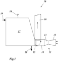
- a gas turbine 11 which sucks in and compresses air with a compressor 12, uses the compressed air to burn a fuel in a combustion chamber (not shown), and expands the resulting hot gases in a turbine 13 to perform work.
- the turbine 13 typically drives the compressor 12 and an electrical generator (not shown).
- the hot exhaust gases emerging from the turbine 13 are fed in combined operation via an exhaust gas duct 14 to a heat recovery steam generator 17 where they convert feed water supplied via a feed water inlet 19 into steam by heat exchange, which is discharged at a superheated steam outlet 20 .
- the cooled exhaust gases leave the heat recovery steam generator 17 via an exhaust gas outlet 18.
- the heat recovery steam generator 17 is part of a water/steam circuit (not shown) with a steam turbine, condenser, feed water tank and feed water pump.
- a secondary chimney 16 branches off from the exhaust gas duct 14 in front of the heat recovery steam generator 17 .
- a deflection flap 15 is arranged in the exhaust gas duct 14, which can be switched between two end positions. In one end position (in 1 shown in dashed lines) it allows the exhaust gases from the gas turbine to the heat recovery steam generator 17 to pass unhindered and at the same time blocks the secondary chimney 16 . This end position is used in the usual combined operation. In the other end position (in 1 drawn in solid) the connection to the heat recovery steam generator 17 is interrupted and the hot exhaust gases are deflected directly into the secondary chimney 16 .
- the deflection flap 15 is switched into this end position when switching from combined operation to single operation, in which only the gas turbine is used without a water/steam cycle 11 is in operation and generating electricity.
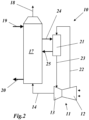
- the turbine 13 and possibly also the combustion chamber are further cooled with air taken from the compressor 12 at one or more points and according to 2 is fed via a compressed air line 22 to a downstream through-flow cooler 21 and cooled down there.
- the through-flow cooler 21 is connected to the heat recovery steam generator 17 via a feed water supply line 24 and a steam discharge line 25 .
- the heat recovery steam generator 17 is supplied with cold feed water via the feed water inlet 19 and with hot exhaust gases from the gas turbine 11 via the exhaust gas duct 14 .
- the feed water is heated through several stages, evaporates and leaves the heat recovery steam generator 17 via the superheated steam outlet 20 as superheated steam.
- the exhaust gases cool down as a result of this heat exchange process and leave the heat recovery steam generator 17 via the exhaust gas outlet 18.
- feedwater is removed from the heat recovery steam generator 17 and fed to the flow cooler 21 via the feedwater supply line 24, where it cools down the compressed air from the gas turbine 11.
- the steam generated in the once-through cooler 21 flows back to the heat recovery steam generator 17 via the steam discharge line 25, while the cooled-down air is routed back to the gas turbine 11 via the compressed air line 23 for cooling purposes.
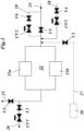
- the shut-off valve V5 in the feed water supply line 24 can be bypassed by a feed water bypass line 29, in which a shut-off valve V6 and a control valve CV2 are installed in series to ensure a smooth change in the feed water pressure when switching from single operation to combined operation.
- a shut-off valve V2 is inserted in the steam discharge line 25 leading to the heat recovery steam generator 17 .
- a steam discharge line 26 branches off, which diverts the steam in single operation, and in which a shut-off valve V1 and a control valve CV1 are installed one after the other.
- the feedwater flows from the heat recovery steam generator 17 in the feedwater supply line 24 through the open shut-off valve V5 at high pressure into the once-through cooler 21.
- the superheated steam is sent back to the overheated part of the heat recovery steam generator 17 via the steam discharge line 25 and the open shut-off valve V2 .
- the shut-off valve V1 is closed.
- feedwater is fed from a separate single-cycle feedwater system 30 via the feedwater supply line 27 at medium pressure via the isolation valve V3, which separates the single-cycle feedwater system 30 from the feedwater system of the heat recovery steam generator 17. Because of corrosion, it is essential that the feed water is provided at a temperature of 150°C in single operation, which is lower than in combined operation.
- the steam generated in the once-through cooler 21 flows out via the steam discharge line 26, the valves V1 and CV1 being used for switching and control purposes.
- the process parameters in combined operation and in single operation differ both in terms of pressure and temperature.
- the cold water mixing line 28 with the valves CV3 and V4 is provided for a gentle temperature transition when switching from combined operation to single operation.
- the feedwater bypass line 29 with the valves CV2 and V6 is there for a stepless change in the feedwater pressure.
- the procedure outlined is important to ensure that pressure overshoot and subcooling in the once-through chiller is minimal.
Landscapes
- Engineering & Computer Science (AREA)
- Chemical & Material Sciences (AREA)
- Combustion & Propulsion (AREA)
- Mechanical Engineering (AREA)
- General Engineering & Computer Science (AREA)
- Life Sciences & Earth Sciences (AREA)
- Sustainable Development (AREA)
- Sustainable Energy (AREA)
- Physics & Mathematics (AREA)
- Thermal Sciences (AREA)
- Engine Equipment That Uses Special Cycles (AREA)
Claims (16)
- Procédé de fonctionnement d'une centrale à cycle combiné (10), qui comprend une turbine à gaz (11) avec un compresseur (12) et une turbine (13), une chaudière de récupération (17) en aval de la turbine à gaz (11) pour la production de vapeur dans un circuit eau-vapeur, ainsi qu'au moins un refroidisseur à circulation (21), à travers lequel circule de l'air comprimé, qui a été comprimé dans le compresseur (12), destiné au refroidissement de la turbine à gaz (11) et, par le refroidissement, de l'eau d'alimentation (24) guidée hors de la chaudière de récupération (17) est transformée en vapeur et débouche au niveau de la chaudière de récupération (17), caractérisé en ce que la centrale à cycle combiné (10), pour rendre plus flexible le fonctionnement sans réduction de la charge de la turbine à gaz (11), est commutée entre un premier mode de fonctionnement (fonctionnement simple), dans lequel seul le circuit de turbine à gaz est utilisé pour la production d'énergie, et un second mode de fonctionnement (fonctionnement combiné), dans lequel le circuit de turbine à gaz et le circuit eau-vapeur sont utilisés pour la production d'énergie, dans lequel lors d'une commutation du second mode de fonctionnement au premier mode de fonctionnement, les gaz d'échappement chauds provenant de la turbine à gaz (11) sont redirigés successivement depuis la chaudière de récupération (17) à l'écart dans une cheminée secondaire (16) et en même temps l'apport en eau d'alimentation provenant de la chaudière de récupération (17) est réduit et remplacé par un autre apport en eau d'alimentation, ou inversement, dans lequel pour l'autre apport en eau d'alimentation, un système d'eau d'alimentation à cycle unique (30) séparé est utilisé et dans lequel, dans la phase de transition, l'eau d'alimentation est mélangée à de l'eau froide au moyen d'une conduite de mélange d'eau froide (28) séparée.
- Procédé selon la revendication précédente, caractérisé en ce que, pour la redirection des gaz d'échappement chauds, un clapet de déviation (15) agencé dans le canal de gaz d'échappement (14) menant de la turbine à gaz (11) à la chaudière de récupération (17) est actionné.
- Procédé selon l'une quelconque des revendications précédentes, caractérisé en ce que, lors de la commutation du second mode de fonctionnement au premier mode de fonctionnement, simultanément l'arrivée de la vapeur provenant du refroidisseur à circulation (21) vers la chaudière de récupération (17) est réduite et la valeur est utilisée ailleurs ou, lors de la commutation du premier mode de fonctionnement au second mode de fonctionnement, simultanément l'arrivée de la vapeur provenant du refroidisseur à circulation (21) vers la chaudière de récupération est augmentée.
- Procédé selon la revendication précédente, caractérisé en ce que la vapeur retirée de la chaudière de récupération (17) est évacuée dans la cheminée secondaire (16).
- Procédé selon la revendication 3, caractérisé en ce que la vapeur retirée de la chaudière de récupération (17) est mélangée à l'air comprimé guidé à travers le refroidisseur à circulation (21).
- Procédé selon la revendication 3, caractérisé en ce que la vapeur retirée de la chaudière de récupération (17) est guidée vers un condenseur refroidi à l'air, afin de réduire au minimum les pertes en eau déminéralisée.
- Procédé selon l'une quelconque des revendications précédentes, caractérisé en ce que l'apport en eau d'alimentation provenant de la chaudière de récupération (17) est réduit au moyen d'une soupape de régulation (CV2) agencée dans une conduite de dérivation d'eau d'alimentation (29), après que l'alimentation du refroidisseur à circulation (21) avec l'eau d'alimentation a été commutée sur la conduite de dérivation d'eau d'alimentation (29) ou inversement.
- Centrale à cycle combiné pour la mise en oeuvre du procédé selon la revendication 1, comprenant une turbine à gaz (11) avec un compresseur (12) et une turbine (13), une chaudière de récupération (17) en aval de la turbine à gaz (11) pour la production de vapeur dans un circuit eau-vapeur, ainsi qu'un refroidisseur à circulation (21), à travers lequel de l'air comprimé, qui a été comprimé dans le compresseur (12), destiné au refroidissement de la turbine à gaz (11) circule et, lors du refroidissement, de l'eau d'alimentation provenant de la chaudière de récupération (17) guidée par le biais d'une première conduite d'eau d'alimentation (24) est transformée en vapeur et débouche par le biais d'une première évacuation de vapeur (25) au niveau de la chaudière de récupération (17), dans laquelle les gaz d'échappement chauds de la turbine à gaz (11) sont guidés par le biais d'un canal de gaz d'échappement (14) vers la chaudière de récupération (17), dans laquelle une cheminée secondaire (16) est détournée du canal de gaz d'échappement (14) et dans laquelle des moyens de réduction de l'apport en eau d'alimentation depuis la chaudière de récupération et pour un autre apport en eau d'alimentation vers le refroidisseur à circulation ainsi qu'une conduite de mélange d'eau froide (28) pour l'apport en eau froide à l'eau d'alimentation sont agencés, dans laquelle les moyens pour l'autre apport en eau d'alimentation au refroidisseur à circulation comprennent un système d'eau d'alimentation à cycle unique (30).
- Centrale à cycle combiné selon la revendication 8, caractérisée en ce que, pour la déviation des gaz d'échappement chauds de la chaudière de récupération (17) vers la cheminée secondaire (16), un clapet de déviation (15) est agencé dans le canal de gaz d'échappement (14).
- Centrale à cycle combiné selon la revendication 8 ou 9,
caractérisée en ce que dans la première évacuation de vapeur (25), une première soupape d'arrêt (V2) est agencée et en ce que de la première évacuation de vapeur (25) avant la première soupape d'arrêt (V2), une seconde évacuation de vapeur (26) est dérivée, prévue pour un premier mode de fonctionnement. - Centrale à cycle combiné selon la revendication précédente, caractérisée en ce que dans la seconde évacuation de vapeur (26) une deuxième soupape d'arrêt (V1) et une première soupape de régulation (CV1) sont agencées l'une derrière l'autre.
- Centrale à cycle combiné selon l'une quelconque des revendications 8 à 11, caractérisée en ce que dans la première conduite d'eau d'alimentation (24) une troisième soupape d'arrêt (V5) est agencée et en ce que pour la déviation de la troisième soupape d'arrêt (V5) une conduite de dérivation d'eau d'alimentation (29) est prévue, dans laquelle sont agencées l'une derrière l'autre une quatrième soupape d'arrêt (V6) et une deuxième soupape de régulation (CV2).
- Centrale à cycle combiné selon la revendication précédente, caractérisée en ce que la conduite de mélange d'eau froide (28) débouche dans la première conduite d'eau d'alimentation (24), entre la conduite de dérivation d'eau d'alimentation (29) et le refroidisseur à circulation (21).
- Centrale à cycle combiné selon la revendication précédente, caractérisée en ce que dans la conduite de mélange d'eau froide (28) une cinquième soupape d'arrêt (V4) et une troisième soupape de régulation (CV3) sont agencées l'une derrière l'autre.
- Centrale à cycle combiné selon la revendication 12,
caractérisée en ce qu'une seconde conduite d'eau d'alimentation (27) provenant du système d'eau d'alimentation à cycle unique (30) séparé débouche dans la première conduite d'eau d'alimentation (24) entre la conduite de dérivation d'eau d'alimentation (29) et le refroidisseur à circulation (21). - Centrale à cycle combiné selon la revendication 15,
caractérisée en ce qu'une sixième soupape d'arrêt (V3) est agencée dans la seconde conduite d'eau d'alimentation (27).
Applications Claiming Priority (1)
| Application Number | Priority Date | Filing Date | Title |
|---|---|---|---|
| CH14062007 | 2007-09-07 |
Publications (4)
| Publication Number | Publication Date |
|---|---|
| EP2067940A2 EP2067940A2 (fr) | 2009-06-10 |
| EP2067940A3 EP2067940A3 (fr) | 2013-06-19 |
| EP2067940B1 EP2067940B1 (fr) | 2019-10-02 |
| EP2067940B2 true EP2067940B2 (fr) | 2023-02-15 |
Family
ID=39301533
Family Applications (1)
| Application Number | Title | Priority Date | Filing Date |
|---|---|---|---|
| EP08162627.7A Active EP2067940B2 (fr) | 2007-09-07 | 2008-08-19 | Procédé de fonctionnement d'ne centrale à cycle combiné, et centrale à cycle combiné pour la mise en oeuvre dudit procédé |
Country Status (3)
| Country | Link |
|---|---|
| US (2) | US8146366B2 (fr) |
| EP (1) | EP2067940B2 (fr) |
| JP (1) | JP5558686B2 (fr) |
Families Citing this family (15)
| Publication number | Priority date | Publication date | Assignee | Title |
|---|---|---|---|---|
| US9435534B2 (en) * | 2009-08-31 | 2016-09-06 | Holistic Engineering Inc | Energy-recovery system for a production plant |
| JP5540209B2 (ja) * | 2009-11-17 | 2014-07-02 | 独立行政法人農業・食品産業技術総合研究機構 | 加熱媒体発生方法 |
| EP2385223A1 (fr) * | 2010-05-04 | 2011-11-09 | Thermal PowerTec GmbH | Procédé d'augmentation du degré d'efficacité d'installations de turbines à gaz et à vapeur |
| ES2578294T3 (es) | 2011-09-07 | 2016-07-22 | Alstom Technology Ltd. | Procedimiento de funcionamiento de una central eléctrica de ciclo combinado |
| CH705929A1 (de) * | 2011-12-22 | 2013-06-28 | Alstom Technology Ltd | Verfahren zum Betreiben eines Kombikraftwerkes. |
| US9429044B2 (en) | 2012-01-13 | 2016-08-30 | Alstom Technology Ltd | Supercritical heat recovery steam generator reheater and supercritical evaporator arrangement |
| EP2775107A1 (fr) | 2013-03-06 | 2014-09-10 | Alstom Technology Ltd | Procédé pour démarrer une centrale électrique à cycle combiné |
| EP2863033B1 (fr) * | 2013-10-21 | 2019-12-04 | Ansaldo Energia IP UK Limited | Turbine à gaz avec système de refroidissement d'air flexible et procédé pour faire fonctionner une turbine à gaz |
| GB2524582B (en) * | 2014-03-28 | 2016-07-20 | Mitsubishi Hitachi Power Sys | Combined cycle gas turbine plant |
| SE539758C2 (en) | 2014-12-04 | 2017-11-21 | Powercell Sweden Ab | Catalytic burner arragement |
| MX392615B (es) | 2017-11-09 | 2025-03-24 | Mitsubishi Hitachi Power Systems Americas Inc | Alimentacion adicional para plantas de energia de ciclo combinado |
| JP6965167B2 (ja) * | 2018-01-12 | 2021-11-10 | 三菱パワー株式会社 | ガスタービンコジェネレーションシステム及びその運転切換方法 |
| US11719156B2 (en) | 2021-03-30 | 2023-08-08 | Doosan Enerbility Co., Ltd. | Combined power generation system with feedwater fuel preheating arrangement |
| EP4071338B1 (fr) * | 2021-04-08 | 2024-01-31 | General Electric Technology GmbH | Système de turbine à gaz comportant des échangeurs de chaleur en série |
| US20260110255A1 (en) * | 2024-10-18 | 2026-04-23 | ACWA POWER Company | Integrated once through cooler water and steam sharing system for multi-unit gas turbine combined cycle power blocks |
Citations (1)
| Publication number | Priority date | Publication date | Assignee | Title |
|---|---|---|---|---|
| EP0773349A1 (fr) † | 1995-11-10 | 1997-05-14 | Asea Brown Boveri Ag | Refroidisseur d'air de refroidissement pour centrales |
Family Cites Families (33)
| Publication number | Priority date | Publication date | Assignee | Title |
|---|---|---|---|---|
| US3953966A (en) * | 1974-08-08 | 1976-05-04 | Westinghouse Electric Corporation | Combined cycle electric power plant having a control system which enables dry steam generator operation during gas turbine operation |
| AT352479B (de) * | 1976-03-08 | 1979-09-25 | Kraftwerk Union Ag | Schutzeinrichtung fuer den abgaskanal einer gas- turbine in einer kombinierten gasturbinen- -dampfkraftanlage |
| US4362013A (en) * | 1980-04-04 | 1982-12-07 | Hitachi, Ltd. | Method for operating a combined plant |
| EP0519304B1 (fr) | 1991-06-21 | 1996-03-13 | Siemens Aktiengesellschaft | Méthode et dispositif pour améliorer un système de turbine à gaz |
| US5267434A (en) * | 1992-04-14 | 1993-12-07 | Siemens Power Corporation | Gas turbine topped steam plant |
| DE4344857A1 (de) | 1993-12-29 | 1995-07-06 | Abb Management Ag | Verfahren und Vorrichtung zum Betreiben einer Gasturbine in einem einfachen und einem mit einer Dampfturbine kombinierten Zyklus |
| US5513488A (en) * | 1994-12-19 | 1996-05-07 | Foster Wheeler Development Corporation | Power process utilizing humidified combusted air to gas turbine |
| DE19508018A1 (de) * | 1995-03-07 | 1996-09-12 | Abb Management Ag | Verfahren zum Betrieb einer Kraftwerksanlage |
| DE19535228C2 (de) * | 1995-09-22 | 2003-05-08 | Alstom | Verfahren zum Betrieb einer Kraftwerksanlage |
| DE19636107C1 (de) | 1996-09-05 | 1998-01-08 | Siemens Ag | Kanalstück für den Rauchgaskanal einer Gasturbine |
| DE19645322B4 (de) * | 1996-11-04 | 2010-05-06 | Alstom | Kombinierte Kraftwerksanlage mit einem Zwangsdurchlaufdampferzeuger als Gasturbinen-Kühlluftkühler |
| KR100584649B1 (ko) * | 1997-05-16 | 2006-05-30 | 지멘스 악티엔게젤샤프트 | 가스 및 증기 터빈 장치, 그리고 상기 방식의 장치내에 있는 가스 터빈의 냉각제를 냉각하는 방법 |
| WO1999057421A1 (fr) * | 1998-05-06 | 1999-11-11 | Siemens Aktiengesellschaft | Installations a turbine a gaz et a turbine a vapeur |
| DE19832294C1 (de) * | 1998-07-17 | 1999-12-30 | Siemens Ag | Gas- und Dampfturbinenanlage |
| DE19901656A1 (de) * | 1999-01-18 | 2000-07-20 | Abb Alstom Power Ch Ag | Verfahren und Vorrichtung zur Regelung der Temperatur am Austritt eines Dampfüberhitzers |
| DE10041413B4 (de) | 1999-08-25 | 2011-05-05 | Alstom (Switzerland) Ltd. | Verfahren zum Betrieb einer Kraftwerksanlage |
| JP4209069B2 (ja) * | 2000-04-18 | 2009-01-14 | 三菱重工業株式会社 | タービン設備 |
| DE10022243A1 (de) * | 2000-05-08 | 2002-02-21 | Alstom Power Nv | Verfahren zum Betrieb eines Kombikraftwerkes sowie Kombikraftwerk zur Durchführung des Verfahrens |
| DE10032625C1 (de) * | 2000-07-07 | 2001-08-02 | Mvv En Ag | Verfahren und Vorrichtung zur gleichzeitigen Wärme- und Heißgaserzeugung mittels Kraftwärmekopplung |
| DE10064263A1 (de) * | 2000-12-22 | 2002-07-04 | Alstom Switzerland Ltd | Strömungsmaschine und Verfahren zum Betrieb |
| EP1262638A1 (fr) * | 2001-05-31 | 2002-12-04 | Siemens Aktiengesellschaft | Dispositif pour refroidir le fluide de refroidissement d'une turbine à gaz et installation à turbine à gaz et à vapeur avec un tel dispositif |
| JP4004800B2 (ja) * | 2002-01-10 | 2007-11-07 | 株式会社東芝 | コンバインドサイクル発電システム |
| JP2004156442A (ja) * | 2002-07-25 | 2004-06-03 | General Electric Co <Ge> | 複合サイクル発電装置の冷却空気システム及びその方法 |
| DE10303341A1 (de) | 2003-01-29 | 2004-08-26 | Alstom Technology Ltd | Luftkühler für Kraftwerksanlagen sowie Anwendung eines solchen Luftkühlers |
| US6922984B2 (en) * | 2003-08-27 | 2005-08-02 | Valero Refining Company - California | Heat recovery circuit |
| EP1682750B1 (fr) * | 2003-10-30 | 2012-11-28 | Alstom Technology Ltd | Centrale electrique |
| JP4469222B2 (ja) * | 2004-05-19 | 2010-05-26 | 東京電力株式会社 | 複合発電プラント |
| US7367177B2 (en) * | 2004-12-14 | 2008-05-06 | Siemens Power Generation, Inc. | Combined cycle power plant with auxiliary air-cooled condenser |
| US20060254280A1 (en) * | 2005-05-12 | 2006-11-16 | Siemens Westinghouse Power Corporation | Combined cycle power plant using compressor air extraction |
| US20060272334A1 (en) * | 2005-06-01 | 2006-12-07 | Pavol Pranda | Practical method for improving the efficiency of cogeneration system |
| JP4811991B2 (ja) * | 2005-07-06 | 2011-11-09 | 株式会社日立製作所 | 高湿分利用ガスタービン設備 |
| CA2641727C (fr) * | 2006-01-09 | 2013-07-30 | Direct Combustion Technologies | Generateur de vapeur a combustion directe |
| EP1808588A1 (fr) * | 2006-01-14 | 2007-07-18 | Thermal PowerTec GmbH | Augmentation de la puissance et du rendement dans des centrales à turbine à gaz et à cycle combiné |
-
2008
- 2008-08-19 EP EP08162627.7A patent/EP2067940B2/fr active Active
- 2008-08-26 US US12/198,359 patent/US8146366B2/en not_active Expired - Fee Related
- 2008-09-03 JP JP2008225440A patent/JP5558686B2/ja not_active Expired - Fee Related
-
2012
- 2012-02-29 US US13/408,140 patent/US8516787B2/en not_active Expired - Fee Related
Patent Citations (1)
| Publication number | Priority date | Publication date | Assignee | Title |
|---|---|---|---|---|
| EP0773349A1 (fr) † | 1995-11-10 | 1997-05-14 | Asea Brown Boveri Ag | Refroidisseur d'air de refroidissement pour centrales |
Also Published As
| Publication number | Publication date |
|---|---|
| EP2067940B1 (fr) | 2019-10-02 |
| US20120167546A1 (en) | 2012-07-05 |
| EP2067940A2 (fr) | 2009-06-10 |
| JP5558686B2 (ja) | 2014-07-23 |
| US20090064656A1 (en) | 2009-03-12 |
| US8146366B2 (en) | 2012-04-03 |
| JP2009062985A (ja) | 2009-03-26 |
| US8516787B2 (en) | 2013-08-27 |
| EP2067940A3 (fr) | 2013-06-19 |
Similar Documents
| Publication | Publication Date | Title |
|---|---|---|
| EP2067940B1 (fr) | Procédé de fonctionnement d'une centrale à cycle combiné, et centrale à cycle combiné pour la mise en oeuvre dudit procédé | |
| DE10041413B4 (de) | Verfahren zum Betrieb einer Kraftwerksanlage | |
| EP0819209B1 (fr) | Procede de fonctionnement d'un generateur de vapeur a recuperation de chaleur, et generateur de vapeur a recuperation de chaleur fonctionnant selon ce procede | |
| EP0563553B1 (fr) | Refroidissement de turbines par air | |
| EP2480762B1 (fr) | Centrale thermique comprenant vanne de régulation de surcharge | |
| EP2067941A2 (fr) | Centrale à cycle combiné avec recirculation des gaz brûlés et séparation de CO2 et méthode de fonctionnement d'une telle centrale à cycle combiné | |
| DE10236324A1 (de) | Verfahren zum Kühlen von Turbinenschaufeln | |
| EP2196633A1 (fr) | Centrale dotée d'une unité de turbine et d'un générateur | |
| EP2798164A2 (fr) | Procédé permettant de faire fonctionner une installation à turbine à gaz et turbine à vapeur pour la stabilisation de la fréquence | |
| EP1795725A1 (fr) | Turbine à gaz avec refroidissement de l'air de refroidissement | |
| EP0666412B1 (fr) | Méthode pour refroidir l'air de refroidissement pour une turbine à gaz | |
| EP2326800B1 (fr) | Centrale à vapeur destinée à la production d'énergie électrique | |
| EP0928365A1 (fr) | Turbine a vapeur, installation de turbine a vapeur et procede de refroidissement de turbine a vapeur | |
| EP3741971A1 (fr) | Agencement de microturbine à gaz | |
| WO1992020905A1 (fr) | Installation a turbine a gaz et a turbine a vapeur | |
| DE10155508C5 (de) | Verfahren und Vorrichtung zur Erzeugung von elektrischer Energie | |
| EP2556218B1 (fr) | Procédé de raccordement rapide d'un générateur de vapeur | |
| EP1854964A1 (fr) | Utilisation de la turbine à vapeur pour la régulation primaire de la fréquence dans des installations de production d'énergie | |
| EP1866521A2 (fr) | Procede permettant de faire demarrer une installation de turbines a gaz et a vapeur | |
| EP1801363A1 (fr) | Centrale électrique | |
| DE2512774A1 (de) | Gasturbinen-heizkraftwerk | |
| EP1896697B1 (fr) | Procédé pour le démarrage d'une installation à turbine à gaz et à vapeur | |
| EP1904731B1 (fr) | Installation combinée de turbines à gaz et à vapeur et son procédé de fonctionnement | |
| EP3759330B1 (fr) | Processus de turbine à gaz étendu avec un dispositif d'expansion | |
| EP2426337A1 (fr) | Dispositif de préchauffage de carburant et procédé de préchauffage de carburant |
Legal Events
| Date | Code | Title | Description |
|---|---|---|---|
| PUAI | Public reference made under article 153(3) epc to a published international application that has entered the european phase |
Free format text: ORIGINAL CODE: 0009012 |
|
| AK | Designated contracting states |
Kind code of ref document: A2 Designated state(s): AT BE BG CH CY CZ DE DK EE ES FI FR GB GR HR HU IE IS IT LI LT LU LV MC MT NL NO PL PT RO SE SI SK TR |
|
| AX | Request for extension of the european patent |
Extension state: AL BA MK RS |
|
| PUAL | Search report despatched |
Free format text: ORIGINAL CODE: 0009013 |
|
| AK | Designated contracting states |
Kind code of ref document: A3 Designated state(s): AT BE BG CH CY CZ DE DK EE ES FI FR GB GR HR HU IE IS IT LI LT LU LV MC MT NL NO PL PT RO SE SI SK TR |
|
| AX | Request for extension of the european patent |
Extension state: AL BA MK RS |
|
| RIC1 | Information provided on ipc code assigned before grant |
Ipc: F01K 23/10 20060101AFI20130514BHEP Ipc: F22B 1/18 20060101ALI20130514BHEP |
|
| 17P | Request for examination filed |
Effective date: 20131022 |
|
| RBV | Designated contracting states (corrected) |
Designated state(s): AT BE BG CH CY CZ DE DK EE ES FI FR GB GR HR HU IE IS IT LI LT LU LV MC MT NL NO PL PT RO SE SI SK TR |
|
| AKX | Designation fees paid |
Designated state(s): AT BE BG CH CY CZ DE DK EE ES FI FR GB GR HR HU IE IS IT LI LT LU LV MC MT NL NO PL PT RO SE SI SK TR |
|
| RAP1 | Party data changed (applicant data changed or rights of an application transferred) |
Owner name: GENERAL ELECTRIC TECHNOLOGY GMBH |
|
| GRAP | Despatch of communication of intention to grant a patent |
Free format text: ORIGINAL CODE: EPIDOSNIGR1 |
|
| STAA | Information on the status of an ep patent application or granted ep patent |
Free format text: STATUS: GRANT OF PATENT IS INTENDED |
|
| INTG | Intention to grant announced |
Effective date: 20190325 |
|
| GRAS | Grant fee paid |
Free format text: ORIGINAL CODE: EPIDOSNIGR3 |
|
| GRAA | (expected) grant |
Free format text: ORIGINAL CODE: 0009210 |
|
| STAA | Information on the status of an ep patent application or granted ep patent |
Free format text: STATUS: THE PATENT HAS BEEN GRANTED |
|
| AK | Designated contracting states |
Kind code of ref document: B1 Designated state(s): AT BE BG CH CY CZ DE DK EE ES FI FR GB GR HR HU IE IS IT LI LT LU LV MC MT NL NO PL PT RO SE SI SK TR |
|
| REG | Reference to a national code |
Ref country code: GB Ref legal event code: FG4D Free format text: NOT ENGLISH |
|
| REG | Reference to a national code |
Ref country code: CH Ref legal event code: EP Ref country code: AT Ref legal event code: REF Ref document number: 1186400 Country of ref document: AT Kind code of ref document: T Effective date: 20191015 |
|
| REG | Reference to a national code |
Ref country code: DE Ref legal event code: R096 Ref document number: 502008016914 Country of ref document: DE |
|
| REG | Reference to a national code |
Ref country code: IE Ref legal event code: FG4D Free format text: LANGUAGE OF EP DOCUMENT: GERMAN |
|
| REG | Reference to a national code |
Ref country code: NL Ref legal event code: MP Effective date: 20191002 |
|
| REG | Reference to a national code |
Ref country code: LT Ref legal event code: MG4D |
|
| PG25 | Lapsed in a contracting state [announced via postgrant information from national office to epo] |
Ref country code: FI Free format text: LAPSE BECAUSE OF FAILURE TO SUBMIT A TRANSLATION OF THE DESCRIPTION OR TO PAY THE FEE WITHIN THE PRESCRIBED TIME-LIMIT Effective date: 20191002 Ref country code: BG Free format text: LAPSE BECAUSE OF FAILURE TO SUBMIT A TRANSLATION OF THE DESCRIPTION OR TO PAY THE FEE WITHIN THE PRESCRIBED TIME-LIMIT Effective date: 20200102 Ref country code: GR Free format text: LAPSE BECAUSE OF FAILURE TO SUBMIT A TRANSLATION OF THE DESCRIPTION OR TO PAY THE FEE WITHIN THE PRESCRIBED TIME-LIMIT Effective date: 20200103 Ref country code: NO Free format text: LAPSE BECAUSE OF FAILURE TO SUBMIT A TRANSLATION OF THE DESCRIPTION OR TO PAY THE FEE WITHIN THE PRESCRIBED TIME-LIMIT Effective date: 20200102 Ref country code: PT Free format text: LAPSE BECAUSE OF FAILURE TO SUBMIT A TRANSLATION OF THE DESCRIPTION OR TO PAY THE FEE WITHIN THE PRESCRIBED TIME-LIMIT Effective date: 20200203 Ref country code: ES Free format text: LAPSE BECAUSE OF FAILURE TO SUBMIT A TRANSLATION OF THE DESCRIPTION OR TO PAY THE FEE WITHIN THE PRESCRIBED TIME-LIMIT Effective date: 20191002 Ref country code: LV Free format text: LAPSE BECAUSE OF FAILURE TO SUBMIT A TRANSLATION OF THE DESCRIPTION OR TO PAY THE FEE WITHIN THE PRESCRIBED TIME-LIMIT Effective date: 20191002 Ref country code: SE Free format text: LAPSE BECAUSE OF FAILURE TO SUBMIT A TRANSLATION OF THE DESCRIPTION OR TO PAY THE FEE WITHIN THE PRESCRIBED TIME-LIMIT Effective date: 20191002 Ref country code: PL Free format text: LAPSE BECAUSE OF FAILURE TO SUBMIT A TRANSLATION OF THE DESCRIPTION OR TO PAY THE FEE WITHIN THE PRESCRIBED TIME-LIMIT Effective date: 20191002 Ref country code: NL Free format text: LAPSE BECAUSE OF FAILURE TO SUBMIT A TRANSLATION OF THE DESCRIPTION OR TO PAY THE FEE WITHIN THE PRESCRIBED TIME-LIMIT Effective date: 20191002 Ref country code: LT Free format text: LAPSE BECAUSE OF FAILURE TO SUBMIT A TRANSLATION OF THE DESCRIPTION OR TO PAY THE FEE WITHIN THE PRESCRIBED TIME-LIMIT Effective date: 20191002 |
|
| PG25 | Lapsed in a contracting state [announced via postgrant information from national office to epo] |
Ref country code: IS Free format text: LAPSE BECAUSE OF FAILURE TO SUBMIT A TRANSLATION OF THE DESCRIPTION OR TO PAY THE FEE WITHIN THE PRESCRIBED TIME-LIMIT Effective date: 20200224 Ref country code: CZ Free format text: LAPSE BECAUSE OF FAILURE TO SUBMIT A TRANSLATION OF THE DESCRIPTION OR TO PAY THE FEE WITHIN THE PRESCRIBED TIME-LIMIT Effective date: 20191002 Ref country code: HR Free format text: LAPSE BECAUSE OF FAILURE TO SUBMIT A TRANSLATION OF THE DESCRIPTION OR TO PAY THE FEE WITHIN THE PRESCRIBED TIME-LIMIT Effective date: 20191002 |
|
| REG | Reference to a national code |
Ref country code: DE Ref legal event code: R026 Ref document number: 502008016914 Country of ref document: DE |
|
| PLBI | Opposition filed |
Free format text: ORIGINAL CODE: 0009260 |
|
| PLAX | Notice of opposition and request to file observation + time limit sent |
Free format text: ORIGINAL CODE: EPIDOSNOBS2 |
|
| PG2D | Information on lapse in contracting state deleted |
Ref country code: IS |
|
| PG25 | Lapsed in a contracting state [announced via postgrant information from national office to epo] |
Ref country code: DK Free format text: LAPSE BECAUSE OF FAILURE TO SUBMIT A TRANSLATION OF THE DESCRIPTION OR TO PAY THE FEE WITHIN THE PRESCRIBED TIME-LIMIT Effective date: 20191002 Ref country code: EE Free format text: LAPSE BECAUSE OF FAILURE TO SUBMIT A TRANSLATION OF THE DESCRIPTION OR TO PAY THE FEE WITHIN THE PRESCRIBED TIME-LIMIT Effective date: 20191002 Ref country code: RO Free format text: LAPSE BECAUSE OF FAILURE TO SUBMIT A TRANSLATION OF THE DESCRIPTION OR TO PAY THE FEE WITHIN THE PRESCRIBED TIME-LIMIT Effective date: 20191002 Ref country code: IS Free format text: LAPSE BECAUSE OF FAILURE TO SUBMIT A TRANSLATION OF THE DESCRIPTION OR TO PAY THE FEE WITHIN THE PRESCRIBED TIME-LIMIT Effective date: 20200202 |
|
| 26 | Opposition filed |
Opponent name: ANSALDO ENERGIA SWITZERLAND AG Effective date: 20200701 |
|
| PG25 | Lapsed in a contracting state [announced via postgrant information from national office to epo] |
Ref country code: SK Free format text: LAPSE BECAUSE OF FAILURE TO SUBMIT A TRANSLATION OF THE DESCRIPTION OR TO PAY THE FEE WITHIN THE PRESCRIBED TIME-LIMIT Effective date: 20191002 |
|
| PLBB | Reply of patent proprietor to notice(s) of opposition received |
Free format text: ORIGINAL CODE: EPIDOSNOBS3 |
|
| PG25 | Lapsed in a contracting state [announced via postgrant information from national office to epo] |
Ref country code: SI Free format text: LAPSE BECAUSE OF FAILURE TO SUBMIT A TRANSLATION OF THE DESCRIPTION OR TO PAY THE FEE WITHIN THE PRESCRIBED TIME-LIMIT Effective date: 20191002 |
|
| PG25 | Lapsed in a contracting state [announced via postgrant information from national office to epo] |
Ref country code: MC Free format text: LAPSE BECAUSE OF FAILURE TO SUBMIT A TRANSLATION OF THE DESCRIPTION OR TO PAY THE FEE WITHIN THE PRESCRIBED TIME-LIMIT Effective date: 20191002 |
|
| REG | Reference to a national code |
Ref country code: CH Ref legal event code: PL |
|
| GBPC | Gb: european patent ceased through non-payment of renewal fee |
Effective date: 20200819 |
|
| PG25 | Lapsed in a contracting state [announced via postgrant information from national office to epo] |
Ref country code: CH Free format text: LAPSE BECAUSE OF NON-PAYMENT OF DUE FEES Effective date: 20200831 Ref country code: LI Free format text: LAPSE BECAUSE OF NON-PAYMENT OF DUE FEES Effective date: 20200831 Ref country code: LU Free format text: LAPSE BECAUSE OF NON-PAYMENT OF DUE FEES Effective date: 20200819 |
|
| REG | Reference to a national code |
Ref country code: BE Ref legal event code: MM Effective date: 20200831 |
|
| PG25 | Lapsed in a contracting state [announced via postgrant information from national office to epo] |
Ref country code: FR Free format text: LAPSE BECAUSE OF NON-PAYMENT OF DUE FEES Effective date: 20200831 |
|
| PG25 | Lapsed in a contracting state [announced via postgrant information from national office to epo] |
Ref country code: BE Free format text: LAPSE BECAUSE OF NON-PAYMENT OF DUE FEES Effective date: 20200831 Ref country code: GB Free format text: LAPSE BECAUSE OF NON-PAYMENT OF DUE FEES Effective date: 20200819 Ref country code: IE Free format text: LAPSE BECAUSE OF NON-PAYMENT OF DUE FEES Effective date: 20200819 |
|
| REG | Reference to a national code |
Ref country code: AT Ref legal event code: MM01 Ref document number: 1186400 Country of ref document: AT Kind code of ref document: T Effective date: 20200819 |
|
| PG25 | Lapsed in a contracting state [announced via postgrant information from national office to epo] |
Ref country code: AT Free format text: LAPSE BECAUSE OF NON-PAYMENT OF DUE FEES Effective date: 20200819 |
|
| PG25 | Lapsed in a contracting state [announced via postgrant information from national office to epo] |
Ref country code: TR Free format text: LAPSE BECAUSE OF FAILURE TO SUBMIT A TRANSLATION OF THE DESCRIPTION OR TO PAY THE FEE WITHIN THE PRESCRIBED TIME-LIMIT Effective date: 20191002 Ref country code: MT Free format text: LAPSE BECAUSE OF FAILURE TO SUBMIT A TRANSLATION OF THE DESCRIPTION OR TO PAY THE FEE WITHIN THE PRESCRIBED TIME-LIMIT Effective date: 20191002 Ref country code: CY Free format text: LAPSE BECAUSE OF FAILURE TO SUBMIT A TRANSLATION OF THE DESCRIPTION OR TO PAY THE FEE WITHIN THE PRESCRIBED TIME-LIMIT Effective date: 20191002 |
|
| PUAH | Patent maintained in amended form |
Free format text: ORIGINAL CODE: 0009272 |
|
| STAA | Information on the status of an ep patent application or granted ep patent |
Free format text: STATUS: PATENT MAINTAINED AS AMENDED |
|
| 27A | Patent maintained in amended form |
Effective date: 20230215 |
|
| AK | Designated contracting states |
Kind code of ref document: B2 Designated state(s): AT BE BG CH CY CZ DE DK EE ES FI FR GB GR HR HU IE IS IT LI LT LU LV MC MT NL NO PL PT RO SE SI SK TR |
|
| REG | Reference to a national code |
Ref country code: DE Ref legal event code: R102 Ref document number: 502008016914 Country of ref document: DE |
|
| P01 | Opt-out of the competence of the unified patent court (upc) registered |
Effective date: 20230522 |
|
| REG | Reference to a national code |
Ref country code: DE Ref legal event code: R082 Ref document number: 502008016914 Country of ref document: DE |
|
| PGFP | Annual fee paid to national office [announced via postgrant information from national office to epo] |
Ref country code: DE Payment date: 20250724 Year of fee payment: 18 |
|
| PGFP | Annual fee paid to national office [announced via postgrant information from national office to epo] |
Ref country code: IT Payment date: 20250723 Year of fee payment: 18 |