EP2067958A2 - Turbosoufflante de gaz d'échappement pour un moteur à combustion interne et dispositif destiné à commuter un dispositif de guidage d'air d'une turbosoufflante de gaz d'échappement - Google Patents
Turbosoufflante de gaz d'échappement pour un moteur à combustion interne et dispositif destiné à commuter un dispositif de guidage d'air d'une turbosoufflante de gaz d'échappement Download PDFInfo
- Publication number
- EP2067958A2 EP2067958A2 EP08170451A EP08170451A EP2067958A2 EP 2067958 A2 EP2067958 A2 EP 2067958A2 EP 08170451 A EP08170451 A EP 08170451A EP 08170451 A EP08170451 A EP 08170451A EP 2067958 A2 EP2067958 A2 EP 2067958A2
- Authority
- EP
- European Patent Office
- Prior art keywords
- compressor
- air
- exhaust gas
- gas turbocharger
- guiding device
- Prior art date
- Legal status (The legal status is an assumption and is not a legal conclusion. Google has not performed a legal analysis and makes no representation as to the accuracy of the status listed.)
- Granted
Links
Images


Classifications
-
- F—MECHANICAL ENGINEERING; LIGHTING; HEATING; WEAPONS; BLASTING
- F02—COMBUSTION ENGINES; HOT-GAS OR COMBUSTION-PRODUCT ENGINE PLANTS
- F02B—INTERNAL-COMBUSTION PISTON ENGINES; COMBUSTION ENGINES IN GENERAL
- F02B37/00—Engines characterised by provision of pumps driven at least for part of the time by exhaust
- F02B37/12—Control of the pumps
- F02B37/22—Control of the pumps by varying cross-section of exhaust passages or air passages, e.g. by throttling turbine inlets or outlets or by varying effective number of guide conduits
- F02B37/225—Control of the pumps by varying cross-section of exhaust passages or air passages, e.g. by throttling turbine inlets or outlets or by varying effective number of guide conduits air passages
-
- F—MECHANICAL ENGINEERING; LIGHTING; HEATING; WEAPONS; BLASTING
- F02—COMBUSTION ENGINES; HOT-GAS OR COMBUSTION-PRODUCT ENGINE PLANTS
- F02B—INTERNAL-COMBUSTION PISTON ENGINES; COMBUSTION ENGINES IN GENERAL
- F02B39/00—Component parts, details, or accessories relating to, driven charging or scavenging pumps, not provided for in groups F02B33/00 - F02B37/00
- F02B39/16—Other safety measures for, or other control of, pumps
-
- F—MECHANICAL ENGINEERING; LIGHTING; HEATING; WEAPONS; BLASTING
- F02—COMBUSTION ENGINES; HOT-GAS OR COMBUSTION-PRODUCT ENGINE PLANTS
- F02D—CONTROLLING COMBUSTION ENGINES
- F02D9/00—Controlling engines by throttling air or fuel-and-air induction conduits or exhaust conduits
- F02D9/08—Throttle valves specially adapted therefor; Arrangements of such valves in conduits
- F02D9/12—Throttle valves specially adapted therefor; Arrangements of such valves in conduits having slidably-mounted valve members; having valve members movable longitudinally of conduit
- F02D9/14—Throttle valves specially adapted therefor; Arrangements of such valves in conduits having slidably-mounted valve members; having valve members movable longitudinally of conduit the members being slidable transversely of conduit
-
- F—MECHANICAL ENGINEERING; LIGHTING; HEATING; WEAPONS; BLASTING
- F02—COMBUSTION ENGINES; HOT-GAS OR COMBUSTION-PRODUCT ENGINE PLANTS
- F02M—SUPPLYING COMBUSTION ENGINES IN GENERAL WITH COMBUSTIBLE MIXTURES OR CONSTITUENTS THEREOF
- F02M35/00—Combustion-air cleaners, air intakes, intake silencers, or induction systems specially adapted for, or arranged on, internal-combustion engines
- F02M35/10—Air intakes; Induction systems
- F02M35/1015—Air intakes; Induction systems characterised by the engine type
- F02M35/10157—Supercharged engines
-
- F—MECHANICAL ENGINEERING; LIGHTING; HEATING; WEAPONS; BLASTING
- F04—POSITIVE - DISPLACEMENT MACHINES FOR LIQUIDS; PUMPS FOR LIQUIDS OR ELASTIC FLUIDS
- F04D—NON-POSITIVE-DISPLACEMENT PUMPS
- F04D29/00—Details, component parts, or accessories
- F04D29/40—Casings; Connections of working fluid
- F04D29/42—Casings; Connections of working fluid for radial or helico-centrifugal pumps
- F04D29/44—Fluid-guiding means, e.g. diffusers
- F04D29/441—Fluid-guiding means, e.g. diffusers especially adapted for elastic fluid pumps
-
- F—MECHANICAL ENGINEERING; LIGHTING; HEATING; WEAPONS; BLASTING
- F02—COMBUSTION ENGINES; HOT-GAS OR COMBUSTION-PRODUCT ENGINE PLANTS
- F02M—SUPPLYING COMBUSTION ENGINES IN GENERAL WITH COMBUSTIBLE MIXTURES OR CONSTITUENTS THEREOF
- F02M35/00—Combustion-air cleaners, air intakes, intake silencers, or induction systems specially adapted for, or arranged on, internal-combustion engines
- F02M35/10—Air intakes; Induction systems
- F02M35/10373—Sensors for intake systems
- F02M35/10386—Sensors for intake systems for flow rate
-
- F—MECHANICAL ENGINEERING; LIGHTING; HEATING; WEAPONS; BLASTING
- F05—INDEXING SCHEMES RELATING TO ENGINES OR PUMPS IN VARIOUS SUBCLASSES OF CLASSES F01-F04
- F05B—INDEXING SCHEME RELATING TO WIND, SPRING, WEIGHT, INERTIA OR LIKE MOTORS, TO MACHINES OR ENGINES FOR LIQUIDS COVERED BY SUBCLASSES F03B, F03D AND F03G
- F05B2220/00—Application
- F05B2220/40—Application in turbochargers
-
- Y—GENERAL TAGGING OF NEW TECHNOLOGICAL DEVELOPMENTS; GENERAL TAGGING OF CROSS-SECTIONAL TECHNOLOGIES SPANNING OVER SEVERAL SECTIONS OF THE IPC; TECHNICAL SUBJECTS COVERED BY FORMER USPC CROSS-REFERENCE ART COLLECTIONS [XRACs] AND DIGESTS
- Y02—TECHNOLOGIES OR APPLICATIONS FOR MITIGATION OR ADAPTATION AGAINST CLIMATE CHANGE
- Y02T—CLIMATE CHANGE MITIGATION TECHNOLOGIES RELATED TO TRANSPORTATION
- Y02T10/00—Road transport of goods or passengers
- Y02T10/10—Internal combustion engine [ICE] based vehicles
- Y02T10/12—Improving ICE efficiencies
Definitions
- the invention relates to an exhaust gas turbocharger for an internal combustion engine, the type specified in the preamble of patent claim 1 and a switchable air guide device of an exhaust gas turbocharger.
- Such an exhaust-gas turbocharger is already known from series-production vehicle construction and usually comprises a compressor, which can be arranged in an intake tract of an internal combustion engine, for precompressed air flow, which is to be conducted through the intake tract to the compressor.
- the compressor takes over the suction of the air flow and promotes the pre-compressed air flow to the engine.
- the drive power of the compressor is supplied by a arranged in an exhaust tract of the internal combustion engine and a shaft rotatably coupled to the compressor exhaust gas turbine, which is driven by the exhaust gases of the internal combustion engine.
- the pre-compressed and heated by the compressor air flow is cooled before entering the cylinders of the internal combustion engine by means of a charge air cooler in order to achieve improved cylinder filling.
- turbo lag comes because the compressor must be accelerated again to the required rated speed to provide the desired boost pressure can.
- Object of the present invention is to provide an exhaust gas turbocharger and a switchable air ducting device for an exhaust gas turbocharger, which allow an improved response of an internal combustion engine.
- an improved response of an internal combustion engine is made possible by the fact that the compressor is preceded by a switchable air ducting device in modular construction of several components, by means of which the compressor is to flow in at least two different ways with the air flow.
- the flow conditions of the Compressor can be varied with the help of the air guide device, whereby it is possible in contrast to the prior art, the air flow, for example, in the part-load and full-load operating mode each differently to the compressor.
- the possibility of a variable flow of the compressor therefore allows an improved consideration of the respective operating mode of the internal combustion engine, resulting in a correspondingly improved response of the same results.
- the air guiding device between a swirl position, in which the air flow before the flow of the compressor is to impart a Drehimpulskomponente, and a power position in which the compressor is fed with an at least substantially rotationally impulsive air flow to switch is.
- the speed of the compressor can be increased, for example under partial load by changing the Anström sculpture without external energy - for example by means of an electric Supporters - would have to be introduced.
- the air guiding device is connected in a swirling position, the compressor thus absorbs less power, whereby a greater part of the power fed in by the exhaust gas turbine can be used to overcome bearing friction forces and the rotational speed of the compressor can be increased accordingly.
- the achievable in this way speed corresponds to the required rated speed, so that at least approximately "windzahistationärer" operation of the compressor can be achieved.
- a switching of the air guiding device in the power position can be used to flow the compressor with an at least substantially rotationally impulsive air flow, in order to obtain no reduction in performance, for example in the full-load operating mode of the internal combustion engine.
- the air flow to be imparted angular momentum component is arranged parallel to an angular momentum of the compressor.
- This allows a particularly advantageous flow to the compressor, since the air flow is swirled in this way in the same direction with a direction of rotation of the compressor and due to the strong Mitdrallströmung a correspondingly high torque can be transmitted to the compressor.
- This allows a significant increase in the speed of the compressor, which thus For example, in part-load operating mode can work as a so-called cold air turbine or impulse turbine.
- the air-guiding device comprises at least one spinal canal and one power canal, wherein the air flow in the fluidized position is to be guided at least predominantly through the spinal canal and in the power position at least predominantly through the power canal.
- the air guiding device comprises a switching flap by means of which a portion of the air flow to be conducted through the swirl duct and / or through the power duct is to be set.
- a switching flap allows rapid switching of the air guide device and can be integrated easily and space-saving in the air guide device.
- the adjustable by means of the switching flap portion of the air flow is preferably a mass fraction. It can also be provided that by means of the switching flap, the entire air flow is to be conducted either through the vortex channel or through the power channel.
- the switching flap should advantageously have switching times of less than 100 ms in order to achieve a fast To ensure response to load changes of the internal combustion engine.
- Another advantage of the switching flap is that the sucked air flow can be throttled specifically, whereby a control of exhaust gas recirculation rates of the internal combustion engine are possible. Furthermore, the efficiency of the internal combustion engine can be worsened by targeted throttling with the aid of the switching flap, whereby the temperature of the exhaust gases increases. This effect can then be used, for example, to improve the emission values during cold start or in internal combustion engines designed as diesel engines for the regeneration of a diesel particulate filter or a NO storage catalytic converter.
- the compressor is not damaged by pressure pulses when moving the switching flap, it has been found to be advantageous in another embodiment that the switching flap is pivotable radially relative to the power channel and the flap is located very close to the compressor to the smallest possible volume between the shot To reach the flap and the compressor wheel.
- the switching flap should have a low weight and can be designed as a thin disc which pivots laterally out of a cavity approximately perpendicular to the power channel in the flow.
- a storage of the flap in the compressor facing away Housing part of the air guide device since lower temperatures are expected.
- the flap bearing can also be integrated in another housing part. To guide the switching flap during actuation and to reduce the frictional forces are formed by the housing slide rails on which the flap can move along.
- end stops for the switching mechanism are provided in the housing of the air guiding device.
- an end stop for the flap in the "power channel open” position is arranged on the inside of the housing, since in this position the flap can be pressed with part of its side surface against the stop and switching mechanism is held by the actuator under tension and thus Noise can be prevented by rattling of switching mechanism or flap.
- a second end stop is provided for the driver outside the housing for the switching position "power channel closed". In this end position, the flap applies to the sealing ring, since the compressor generates a negative pressure, which pulls the flap on the seal and the lever for actuating the flap is clamped to the end stop.
- the switching flap is slidably mounted in the direction of the pivot axis or as a component so yielding that a contact with the sealing disc and a sliding minimally offset in the direction of the pivot axis in the position "power channel" is possible.
- Such a displacement of the flap position in the direction of the pivot axis can be achieved by an axial bearing clearance or a special design of the switching flap, for example, if the flap surface is connected via a resilient web to the bearing point.
- the switching flap can be operated in various ways.
- pneumatic actuators such as under or over-pressure or electric drives into consideration. It is also possible to actuate the switching flap magnetically.
- the actuator is suitably attached to one of the housing parts of the air guiding device. It is advantageous to mount on the housing part, which forms the storage of the switching flap to avoid unnecessary tolerances.
- the sealing washer is preferably made of a slid-optimized material or has at least one surface with low friction.
- a slid-optimized material is, for example, Teflon.
- a Strömungsleitgitter for introducing the air from the vortex channel in the power channel can be arranged between the flap and the compressor.
- the Strömungsleitgitter is inserted into the lower part or the compressor housing and held firmly with an additional spacer ring to the corresponding housing part.
- it can be designed with a favorable embodiment of the swirl duct without Strömungsleitgitter.
- the flow direction of the air flow can be particularly easily and variably deflected and provided, for example with the angular momentum component.
- the air guide element for this purpose one or more vanes with variable blade profiles or blade angles or have different flow cross-sections and is thus optimally adapted to the respective structural and fluidic conditions.
- the air-guiding device can be designed to save space in a particularly space-saving manner by arranging the swirl duct on an outer circumference of the power duct.
- the vertebral channel is at least partially formed spirally. This represents a structurally simple way to form the vortex channel as flow volutes and to use for targeted deflection of the air flow.
- the air guide device is mechanically, in particular by means of an over- and / or vacuum unit, and / or to switch electronically. This allows a particularly variable embodiment of the exhaust gas turbocharger and a simple adaptability to different structural conditions, equipment lines or the like.
- the air guiding device is associated with a housing, via which the air guiding device can be coupled to the exhaust gas turbocharger and / or the intake tract.
- the air guiding device can in principle also be integrated into an already existing compressor housing of the exhaust gas turbocharger, such a housing offers the advantage that the Air guiding device may be formed as an independent component and thus easily coupled with existing exhaust gas turbochargers or offered as a retrofit solution.
- a reduction of storage costs and maintenance and repair costs is achieved due to the variable design options of the air guide device.
- the individual components can be connected in various ways. One embodiment is the assembly with screws. But there are also other methods, such as welding, clipping or gluing possible.
- the housing components of the air guiding device 21 various materials are conceivable.
- the housing of compressors are made of a metal material.
- the air guiding device can also be made of temperature-resistant plastic, such as polyamide or other engineering plastics.
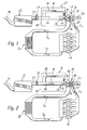
- FIG. 1 a schematic diagram of an internal combustion engine with an exhaust gas turbocharger, the air intake device according to an embodiment in an intake tract upstream, wherein the air guiding device is connected in a swirling position;
- FIG. 2 a schematic diagram of the in FIG. 1 shown internal combustion engine, wherein the air guiding device is connected in a power position;
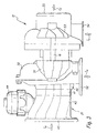
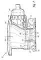
- FIG. 3 the housing of an exhaust gas turbocharger with mounted air guide device
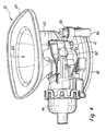
- FIG. 4 a switchable air guide device with actuator and push rod in a perspective side view
- FIG. 5 a switchable air guide device without actuator in a perspective side view
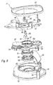
- FIG. 6 an exploded perspective view of the air duct device with parts
- FIG. 7 a sectional view along the longitudinal axis through the air guide device
- FIG. 8 a perspective view of the upper housing part in the switching position "power channel open"
- FIG. 9 a perspective view of the upper housing part in the switching position "power channel closed”.
- Fig. 1 shows a schematic diagram of a trained in the present embodiment as a four-cylinder diesel engine
- Internal combustion engine 10 with an exhaust gas turbocharger 12 which comprises a compressor 13 in an intake tract 14 and a non-rotatably connected via a shaft 16 with the compressor 13 exhaust gas turbine 18 in an exhaust tract 20.
- the internal combustion engine 10 is designed as a gasoline engine with stratified direct injection.
- the guided through the exhaust system 20 exhaust gases of the internal combustion engine 10 drive via the exhaust gas turbine 18 to the compressor 13, which in turn pre-compressed the guided through the intake air flow 14.
- the compressor 13 of the exhaust gas turbocharger 12 is in the intake 14 an incorporated in a housing 19 air guide device 21 upstream, by means of which the compressor 13 is inflict on at least two different ways with the air flow and their operation will be explained in more detail below.
- the air flow is finally passed through a known intercooler 26, by means of which the heated by the compressor 13, precompressed air is cooled before entering the internal combustion engine 10.
- the arrows la and Ib indicate the direction of flow of the air flow in the intake tract 14, the arrows Ic and Id the direction of flow of the resulting combustion within the internal combustion engine 10 exhaust gases in the exhaust system 20.
- the sucked into the intake 14 air flow is first cleaned by means of an air filter 22 , Subsequently, via a downstream of the air filter 22 air mass meter 24, which is presently designed as H thoroughlyfiluuftmassenmesser, the mass of the air flow to control the subsequent combustion process determined.
- the air mass meter 24 may optionally provide important control variables for an exhaust gas recirculation system (not shown).
- the compressor 13 of the exhaust gas turbocharger 12 upstream air guide device 21 comprises a swirl duct 28, a power channel 30 and a pivotable switching flap 32, by means of which the air flow between the swirl duct 28 and the power channel 30 can be divided.
- the switching flap 32 is arranged as close as possible to the compressor 13 in order to minimize the volume between the compressor 13 and the switching flap 32 and thus the volume within which an angular momentum component of the air stream could weaken undesirably.
- the switching flap 32 completely closes the power duct 30 in the swirling position of the air guiding device 21 shown, so that the air flow is directed exclusively through the swirl duct 28 according to arrow W. Alternatively, however, it can also be provided that a part of the air flow is additionally conducted according to arrow L through the power channel 30.
- the air flow is evenly distributed to an air guide element 34, which is arranged at the end of the swirl duct 28 and consists of several, applied to a circular ring 36 vanes 38 (S. Fig.
- the air flow is given a rotational momentum component which is arranged parallel to an angular momentum of the compressor 13.
- a swirling air flow is generated, by means of which the compressor 13 is supplied with a strong Mitdrall, so that a driving impulsive force exerted on the compressor 13 and the speed of the compressor 13 is increased accordingly.
- the compressor 13 during load change into the full-load operating mode of the internal combustion engine 10 (s. Fig. 2 ) are not first accelerated back to the required rated speed, so that a quick response of the internal combustion engine 10 is ensured.
- a particularly large increase in speed can be achieved that the compressor 13 is impressed by the air flow such a strong Mitdrall that the compressor 13 operates in part-load operating mode of the internal combustion engine 10 as a so-called cold air turbine or impulse turbine.
- Fig. 2 shows a schematic diagram of the internal combustion engine 10 according to Fig. 1 , wherein the air guide device 21 is switched to a power position in which the switching flap 32 completely releases both the spinal canal 28 and the power channel 30.
- the switching operation between the swirl and the power position takes place during the load change of the internal combustion engine 10 between the part-load and the full-load operating mode. Since the compressor 13 in the full load operating mode To avoid a reduction in performance of the internal combustion engine 10 must be supplied with swirl-free air flow as possible, at least the majority of the air flow in the power position according to arrow L passed through the power channel 30 and flows the compressor 13 twist-free or macroscopically without parallel to an angular momentum of Compressor 13 arranged angular momentum component.
- Fig. 3 shows in a schematic representation of the housing of an exhaust gas turbocharger 12 with an attached switchable air guide device 21.
- the guided through the exhaust tract 20 exhaust gases of the internal combustion engine 10 drive via the exhaust gas turbine 18 to the compressor 13, which then precompressed by the intake 14 directed air flow.
- the compressor 13 of the exhaust gas turbocharger 12 is in the intake 14 an incorporated in a housing 19 air guide device 21 upstream, by means of which the compressor 13 can be flowed in at least two different ways with the air flow and their structure will be explained in more detail below. Shown are the inflow direction into the turbine side Ic and the turbine-side outflow direction Id and inflow Ie in the air guide device 21 and outflow Ia from the compressor.
- the air guiding device 21 is connected to the connecting line 45 with the clean air line 23. This connection can be made with coupling means familiar to the person skilled in the art, such as bayonet locks, hose clamps, Henn coupling or the like.
- the air guiding device 21 is fixedly connected to the compressor housing 50. In the illustrated embodiment, a portion of the air guide device 21 forms part of the compressor housing 50.
- the air compressed via the compressor wheel 51 flows out of the compressor outlet 52 via a charge air cooler 26 into the combustion chamber of the internal combustion engine 10.
- the compressor wheel 51 is moved by a shaft 16 from the turbine wheel 53 driven on the exhaust side of the exhaust gas turbocharger 12. On the turbine side with the Turbine inlet opening 54, the exhaust gas flows past the turbine wheel 53 to the turbine outlet 55th
- Fig. 4 shows a perspective view of a multi-part housing, in this case made of plastic, a switchable air guide device 21, consisting of an upper part 40 and a lower part 46 with a middle part arranged therebetween 41.
- the sucked by the exhaust gas turbocharger 12 air flows through the air inlet 68 on the clean air side connecting flange 45 in the air guiding device 21 a.
- a mounted on the upper part 40 of the air guide device actuator 44 is connected via a push rod 61 and a lever 62 to the switching device 32. Shown is a vacuum actuator 44 which is controlled via a switching valve (not shown).
- Fig. 5 shows the perspective view of a switchable air guide device 21 without the representation of the actuator 44.
- the upper part 40 is fixedly connected to the middle part 41 and the lower part 46 via a number of attachment points 64.
- the clean air enters from the air filter 22 via the air inlet 60 on the clean air line 23 corresponding connecting flange 45 in the air guide device 21 and after the compression of the air in the compressor 13, this flows out of the compressor outlet 52.
- the flange at the compressor outlet 52 is formed by the lower part 46, which is connected to the compressor housing 50 of the exhaust gas turbocharger 12.
- a sealing ring (not shown) or other suitable sealing means, such as a liquid seal is provided.
- the shift lever 62 shown is provided with a ball head to allow optimum mobility of the push rod 61 on the shift lever 62.
- a housing-fixed stop surface 65 limits the angle of rotation of the shift lever 62 and thus the pivoting flap 32 in the direction of "power channel open".
- Fig. 6 shows an exploded perspective view of the Fig. 4
- the upper part 40 forms the connecting flange 45 to the clean air line 23 and the attachment points 76 for fixing an actuator 44.
- the shaft 66 is mounted for transmitting the forces of the actuator 44 to the switching device 32 in the upper part 40.
- This shaft 66 connects the switching device 32 with the shift lever 62. This may be connected by a screw 67 or other method with the shaft.
- a pivoting flap 32 is arranged, which can close and open the power channel inlet 68 by a rotation about the pivot axis III, while the spinal canal inlet 69 remains constantly open.
- a tribologically optimized sliding ring 42 is arranged, which allows a slight movement of the pivoting flap 32 over the edge of the power channel inlet 68.
- through-holes 70 are arranged on the circumference 41 on the circumference, which allow a screwing of the central part 41 between the upper part 40 and the lower part 46.
- Adjoining the middle part 41, the lower part 46, which forms part of the compressor housing 50, between a spacer ring 71 and a Strömungsleitgitter 34 is inserted.
- the Strömungsleitgitter 34 consists of a circular ring 36 with attached guide vanes 38.
- the lower part 46 forms near the middle part 41 predominantly the spinal canal 28 and partially the Verêtrvolute 72 and the fastening device 64 for middle part 41 and upper part 40 from.
- the lower part 46 is fixedly connected to the compressor housing 50.
- Fig. 7 is a sectional view of the air guide device 21 according to FIG. 2 along the longitudinal axis of the power channel 30.
- the filtered clean air flows at the air inlet 60 in the funnel-shaped upper part 40, which is connected via the connecting flange 45 with the clean air line 23 (not shown), in the air guide device 21 a.
- Fixed to the upper part 40 is the actuator 44, which actuates the pivoting flap 32.
- the central portion 41 forms the main flow direction of the power channel 30 and around the power channel 30 spiral around vortex channel 28.
- the vortex channel 28 is designed as a flow volume and allows the air to flow transversely to the main flow direction between the guide vanes 38 of the Strömungsleitgitters 34 tangentially into the power channel 30.
- the division of the air flow into two partial flows, into the swirl duct 28 and the power duct 30, takes place through the design of the middle part 41, which separates the air inlet swirl duct 69 from the air inlet power duct 68 by the housing shape.
- the pivoting flap 32 is movably mounted. In the area outside the air inlet power channel 68, the pivoting flap 32 through the slideways 73 in the upper part 40 and central part 41 supported.
- the air inlet power channel 68 can be partially or completely closed by the pivoting flap 32.
- the inlet opening power channel 68 is preset on a sliding disk 42, on which the pivoting flap 32 rests.
- a spacer 71 and the Strömungsleitgitter 34 are inserted, which together form a portion of the power channel 30 and are held by heels between the middle part 41 and lower part 46.
- the power channel 30 merges in the lower part 46 into the volute of the compressor housing 50, which is formed in part by the lower part 46.
- Fig. 8 shows a perspective bottom view of the upper part 40 with the pivoting flap 32 in the switching position "power channel open” (actuator not shown).
- the cross-sectional opening 74 for the air to flow into the inlet power channel 68 and the entrance swirl duct 69 are completely open.
- the pivoting flap 32 bears against a stop surface 75 and is supported on the slide tracks 73.
- the torque of the switching shaft 66 is transmitted via a flat edge on the pivoting flap 32.
- Fig. 9 shows a bottom perspective view of the upper part 40 with the pivoting flap 32 in the switching position "power channel closed” (actuator not shown).
- the shift lever 62 abuts against the abutment surface 65.
- the cross-sectional opening 74 for the air to Inflow into the inlet power channel 68 and the entrance swirl duct 69 is partially closed, so that the pivoting flap 32 completely closes the air inlet power channel 68 in the middle part 41 while the air inlet swirl duct 69 remains free.
Landscapes
- Engineering & Computer Science (AREA)
- Mechanical Engineering (AREA)
- General Engineering & Computer Science (AREA)
- Chemical & Material Sciences (AREA)
- Combustion & Propulsion (AREA)
- Supercharger (AREA)
Applications Claiming Priority (1)
| Application Number | Priority Date | Filing Date | Title |
|---|---|---|---|
| DE102007058615A DE102007058615A1 (de) | 2007-12-04 | 2007-12-04 | Abgasturbolader für eine Brennkraftmaschine und Vorrichtung zum Schalten einer Luftführungsvorrichtung eines Abgasturboladers |
Publications (3)
| Publication Number | Publication Date |
|---|---|
| EP2067958A2 true EP2067958A2 (fr) | 2009-06-10 |
| EP2067958A3 EP2067958A3 (fr) | 2009-11-25 |
| EP2067958B1 EP2067958B1 (fr) | 2012-02-01 |
Family
ID=40430152
Family Applications (1)
| Application Number | Title | Priority Date | Filing Date |
|---|---|---|---|
| EP08170451A Not-in-force EP2067958B1 (fr) | 2007-12-04 | 2008-12-02 | Turbosoufflante de gaz d'échappement pour un moteur à combustion interne et dispositif destiné à commuter un dispositif de guidage d'air d'une turbosoufflante de gaz d'échappement |
Country Status (4)
| Country | Link |
|---|---|
| US (1) | US8156741B2 (fr) |
| EP (1) | EP2067958B1 (fr) |
| AT (1) | ATE543992T1 (fr) |
| DE (1) | DE102007058615A1 (fr) |
Cited By (1)
| Publication number | Priority date | Publication date | Assignee | Title |
|---|---|---|---|---|
| EP2682592A3 (fr) * | 2012-07-06 | 2014-07-02 | Kabushiki Kaisha Toyota Jidoshokki | Structures d'alimentation en air d'admission pour suralimentation de turbocompresseur |
Families Citing this family (13)
| Publication number | Priority date | Publication date | Assignee | Title |
|---|---|---|---|---|
| US8177498B2 (en) * | 2009-04-21 | 2012-05-15 | Ford Global Technologies, Llc | Inlet swirl control for turbochargers |
| US8666634B2 (en) * | 2011-02-25 | 2014-03-04 | Bendix Commercial Vehicle Systems Llc | Method of operating a vehicle equipped with a pneumatic booster system |
| US8505297B2 (en) * | 2011-02-25 | 2013-08-13 | Bendix Commercial Vehicle Systems Llc | Method of operating a vehicle equipped with a pneumatic booster system |
| US8484971B2 (en) * | 2011-02-25 | 2013-07-16 | Bendix Commercial Vehicle Systems Llc | Method of operating a vehicle equipped with a pneumatic booster system |
| US8468824B2 (en) * | 2011-02-25 | 2013-06-25 | Bendix Commercial Vehicle Systems Llc | Method of operating a vehicle equipped with a pneumatic booster system |
| US20120222643A1 (en) * | 2011-03-01 | 2012-09-06 | Mann+Hummel Gmbh | Swirl guiding acoustic device with an internal coaxially integrated swirl guide structure |
| US8820071B2 (en) * | 2011-07-20 | 2014-09-02 | GM Global Technology Operations LLC | Integrated compressor housing and inlet |
| DE102011111747A1 (de) * | 2011-08-24 | 2013-02-28 | Daimler Ag | Verdichter für einen Abgasturbolader |
| DE102014217996A1 (de) * | 2014-09-09 | 2016-03-10 | Bayerische Motoren Werke Aktiengesellschaft | Abgasturbolader für eine Verbrennungskraftmaschine sowie Verfahren zum Herstellen eines solchen Agasturboladers |
| DE102015207573B4 (de) * | 2015-04-24 | 2023-07-06 | Ford Global Technologies, Llc | Brennkraftmaschine mit kombiniertem Abgasnachbehandlungssystem |
| US10844817B2 (en) * | 2018-04-23 | 2020-11-24 | Ford Global Technologies, Llc | Convolute-swirl integrated duct for swirl generation |
| US11208971B2 (en) * | 2019-01-16 | 2021-12-28 | Ford Global Technologies, Llc | Methods and systems for mitigating condensate formation |
| CN114877463A (zh) * | 2022-04-27 | 2022-08-09 | 上海伯涵热能科技有限公司 | 一种带有装饰性电动风门的门扇 |
Family Cites Families (13)
| Publication number | Priority date | Publication date | Assignee | Title |
|---|---|---|---|---|
| US3232043A (en) * | 1964-01-13 | 1966-02-01 | Birmann Rudolph | Turbocompressor system |
| US3672786A (en) * | 1970-11-02 | 1972-06-27 | Carrier Corp | Capacity control mechanism for centrifugal gas compressors |
| FR2127393A5 (fr) * | 1971-03-05 | 1972-10-13 | Constr Telephoniques | |
| US3922108A (en) * | 1974-03-18 | 1975-11-25 | Wallace Murray Corp | Pre-whirl turbo charger apparatus |
| US5025629A (en) * | 1989-03-20 | 1991-06-25 | Woollenweber William E | High pressure ratio turbocharger |
| JPH116500A (ja) * | 1997-06-17 | 1999-01-12 | Toyota Central Res & Dev Lab Inc | 遠心圧縮機の旋回流発生装置 |
| US6328024B1 (en) * | 1999-03-30 | 2001-12-11 | Mark S. Kibort | Axial flow electric supercharger |
| DE10250302B4 (de) * | 2002-10-29 | 2004-12-09 | Bayerische Motoren Werke Ag | Drallerzeugungseinrichtung für einen Verdichter |
| JP4464661B2 (ja) * | 2002-11-13 | 2010-05-19 | ボーグワーナー・インコーポレーテッド | 遠心圧縮機のための事前旋回発生装置 |
| EP1482128B1 (fr) * | 2003-05-28 | 2006-10-11 | Ford Global Technologies, LLC | Moteur à combustion interne suralimenté |
| GB0408190D0 (en) * | 2004-04-13 | 2004-05-19 | Integral Powertrain Ltd | Turbo-compressor map-width enhancer |
| FR2878914B1 (fr) * | 2004-12-03 | 2010-09-03 | Inst Francais Du Petrole | Compresseur d'air, notamment pour moteur a combustion interne, comprenant une chambre de mise en rotation de l'air admis |
| US7874789B2 (en) * | 2007-04-06 | 2011-01-25 | Honeywell International, Inc. | Compressor and compressor housing |
-
2007
- 2007-12-04 DE DE102007058615A patent/DE102007058615A1/de not_active Withdrawn
-
2008
- 2008-12-02 EP EP08170451A patent/EP2067958B1/fr not_active Not-in-force
- 2008-12-02 AT AT08170451T patent/ATE543992T1/de active
- 2008-12-04 US US12/328,047 patent/US8156741B2/en not_active Expired - Fee Related
Cited By (1)
| Publication number | Priority date | Publication date | Assignee | Title |
|---|---|---|---|---|
| EP2682592A3 (fr) * | 2012-07-06 | 2014-07-02 | Kabushiki Kaisha Toyota Jidoshokki | Structures d'alimentation en air d'admission pour suralimentation de turbocompresseur |
Also Published As
| Publication number | Publication date |
|---|---|
| US20090139228A1 (en) | 2009-06-04 |
| EP2067958B1 (fr) | 2012-02-01 |
| US8156741B2 (en) | 2012-04-17 |
| ATE543992T1 (de) | 2012-02-15 |
| EP2067958A3 (fr) | 2009-11-25 |
| DE102007058615A1 (de) | 2009-06-10 |
Similar Documents
| Publication | Publication Date | Title |
|---|---|---|
| EP2067958B1 (fr) | Turbosoufflante de gaz d'échappement pour un moteur à combustion interne et dispositif destiné à commuter un dispositif de guidage d'air d'une turbosoufflante de gaz d'échappement | |
| EP1274928B1 (fr) | Dispositif turbocompresseur pour un moteur a combustion interne | |
| EP1639245B1 (fr) | Moteur a combustion interne comportant un compresseur dans la pipe d'admission et procede correspondant | |
| DE102010053951B4 (de) | Turbine für einen Abgasturbolader | |
| EP2211048B1 (fr) | Dispositif de clapets de gaz d'échappement et système de récupération thermique à l'échappement d'un moteur à combustion interne | |
| WO2008125381A1 (fr) | Carter de compresseur et turbocompresseur | |
| DE19511232A1 (de) | Verfahren und Vorrichtung zur Registeraufladung einer Brennkraftmaschine | |
| WO2014124807A1 (fr) | Moteur à combustion interne à suralimentation | |
| EP1546524B1 (fr) | Dispositif pour comprimer de l'air de combustion avec dispositif de derivation integre | |
| WO2010069301A2 (fr) | Turbines à variabilité intégrale pour turbocompresseurs | |
| EP1530671B1 (fr) | Turbocompresseur à gaz d'échappement pour moteur à combustion | |
| EP3682116A1 (fr) | Compresseur radial comprenant un mécanisme à diaphragme iris pour un dispositif de charge d'un moteur à combustion interne, dispositif de charge et lamelle pour le mécanisme à diaphragme iris | |
| EP1881162B1 (fr) | Turbocompresseur pour moteur à combustion interne | |
| DE4312077C1 (de) | Abgasturbolader für eine aufgeladene Brennkraftmaschine | |
| DE102012015536A1 (de) | Abgasanlage für eine Brennkraftmaschine | |
| DE102008060251B4 (de) | Abgasturbolader mit variabler Turbinengeometrie | |
| DE19821130B4 (de) | Brennkraftmaschine mit einer Motorstaubremse | |
| DE102010020709A1 (de) | Steuereinrichtung für eine turboaufgeladene Verbrennungskraftmaschine | |
| DE102010051777A1 (de) | Turbine für einen Abgasturbolader einer Verbrennungskraftmaschine | |
| EP1762716B1 (fr) | Frein d'échappement avec une conduite de bypass | |
| DE10352712A1 (de) | Mehrstufige Luftversorgungseinrichtung mit Zweistrom-Maschine | |
| DE102007058603A1 (de) | Abgasturbolader für eine Brennkraftmaschine und Verfahren zum Schalten einer Luftführungsvorrichtung eines Abgasturboladers | |
| EP1838958A1 (fr) | Vehicule a systeme de recyclage des gaz d'echappement | |
| DE102005062682A1 (de) | Verdichter im Ansaugtrakt einer Brennkraftmaschine und Abgasturbolader für eine Brennkraftmaschine | |
| EP1746263B1 (fr) | Système de soupape pour un échangeur de chaleur |
Legal Events
| Date | Code | Title | Description |
|---|---|---|---|
| PUAI | Public reference made under article 153(3) epc to a published international application that has entered the european phase |
Free format text: ORIGINAL CODE: 0009012 |
|
| AK | Designated contracting states |
Kind code of ref document: A2 Designated state(s): AT BE BG CH CY CZ DE DK EE ES FI FR GB GR HR HU IE IS IT LI LT LU LV MC MT NL NO PL PT RO SE SI SK TR |
|
| AX | Request for extension of the european patent |
Extension state: AL BA MK RS |
|
| PUAL | Search report despatched |
Free format text: ORIGINAL CODE: 0009013 |
|
| AK | Designated contracting states |
Kind code of ref document: A3 Designated state(s): AT BE BG CH CY CZ DE DK EE ES FI FR GB GR HR HU IE IS IT LI LT LU LV MC MT NL NO PL PT RO SE SI SK TR |
|
| AX | Request for extension of the european patent |
Extension state: AL BA MK RS |
|
| 17P | Request for examination filed |
Effective date: 20100121 |
|
| 17Q | First examination report despatched |
Effective date: 20100222 |
|
| AKX | Designation fees paid |
Designated state(s): AT BE BG CH CY CZ DE DK EE ES FI FR GB GR HR HU IE IS IT LI LT LU LV MC MT NL NO PL PT RO SE SI SK TR |
|
| GRAP | Despatch of communication of intention to grant a patent |
Free format text: ORIGINAL CODE: EPIDOSNIGR1 |
|
| GRAS | Grant fee paid |
Free format text: ORIGINAL CODE: EPIDOSNIGR3 |
|
| RAP1 | Party data changed (applicant data changed or rights of an application transferred) |
Owner name: DAIMLER AG Owner name: MANN+HUMMEL GMBH |
|
| GRAA | (expected) grant |
Free format text: ORIGINAL CODE: 0009210 |
|
| AK | Designated contracting states |
Kind code of ref document: B1 Designated state(s): AT BE BG CH CY CZ DE DK EE ES FI FR GB GR HR HU IE IS IT LI LT LU LV MC MT NL NO PL PT RO SE SI SK TR |
|
| REG | Reference to a national code |
Ref country code: GB Ref legal event code: FG4D Free format text: NOT ENGLISH |
|
| REG | Reference to a national code |
Ref country code: AT Ref legal event code: REF Ref document number: 543992 Country of ref document: AT Kind code of ref document: T Effective date: 20120215 Ref country code: CH Ref legal event code: EP |
|
| REG | Reference to a national code |
Ref country code: DE Ref legal event code: R096 Ref document number: 502008006291 Country of ref document: DE Effective date: 20120322 |
|
| REG | Reference to a national code |
Ref country code: NL Ref legal event code: VDEP Effective date: 20120201 |
|
| LTIE | Lt: invalidation of european patent or patent extension |
Effective date: 20120201 |
|
| PG25 | Lapsed in a contracting state [announced via postgrant information from national office to epo] |
Ref country code: NL Free format text: LAPSE BECAUSE OF FAILURE TO SUBMIT A TRANSLATION OF THE DESCRIPTION OR TO PAY THE FEE WITHIN THE PRESCRIBED TIME-LIMIT Effective date: 20120201 Ref country code: HR Free format text: LAPSE BECAUSE OF FAILURE TO SUBMIT A TRANSLATION OF THE DESCRIPTION OR TO PAY THE FEE WITHIN THE PRESCRIBED TIME-LIMIT Effective date: 20120201 Ref country code: IS Free format text: LAPSE BECAUSE OF FAILURE TO SUBMIT A TRANSLATION OF THE DESCRIPTION OR TO PAY THE FEE WITHIN THE PRESCRIBED TIME-LIMIT Effective date: 20120601 Ref country code: NO Free format text: LAPSE BECAUSE OF FAILURE TO SUBMIT A TRANSLATION OF THE DESCRIPTION OR TO PAY THE FEE WITHIN THE PRESCRIBED TIME-LIMIT Effective date: 20120501 Ref country code: LT Free format text: LAPSE BECAUSE OF FAILURE TO SUBMIT A TRANSLATION OF THE DESCRIPTION OR TO PAY THE FEE WITHIN THE PRESCRIBED TIME-LIMIT Effective date: 20120201 |
|
| REG | Reference to a national code |
Ref country code: IE Ref legal event code: FD4D |
|
| PG25 | Lapsed in a contracting state [announced via postgrant information from national office to epo] |
Ref country code: FI Free format text: LAPSE BECAUSE OF FAILURE TO SUBMIT A TRANSLATION OF THE DESCRIPTION OR TO PAY THE FEE WITHIN THE PRESCRIBED TIME-LIMIT Effective date: 20120201 Ref country code: GR Free format text: LAPSE BECAUSE OF FAILURE TO SUBMIT A TRANSLATION OF THE DESCRIPTION OR TO PAY THE FEE WITHIN THE PRESCRIBED TIME-LIMIT Effective date: 20120502 Ref country code: LV Free format text: LAPSE BECAUSE OF FAILURE TO SUBMIT A TRANSLATION OF THE DESCRIPTION OR TO PAY THE FEE WITHIN THE PRESCRIBED TIME-LIMIT Effective date: 20120201 Ref country code: PL Free format text: LAPSE BECAUSE OF FAILURE TO SUBMIT A TRANSLATION OF THE DESCRIPTION OR TO PAY THE FEE WITHIN THE PRESCRIBED TIME-LIMIT Effective date: 20120201 Ref country code: PT Free format text: LAPSE BECAUSE OF FAILURE TO SUBMIT A TRANSLATION OF THE DESCRIPTION OR TO PAY THE FEE WITHIN THE PRESCRIBED TIME-LIMIT Effective date: 20120601 |
|
| PG25 | Lapsed in a contracting state [announced via postgrant information from national office to epo] |
Ref country code: CY Free format text: LAPSE BECAUSE OF FAILURE TO SUBMIT A TRANSLATION OF THE DESCRIPTION OR TO PAY THE FEE WITHIN THE PRESCRIBED TIME-LIMIT Effective date: 20120201 |
|
| PG25 | Lapsed in a contracting state [announced via postgrant information from national office to epo] |
Ref country code: CZ Free format text: LAPSE BECAUSE OF FAILURE TO SUBMIT A TRANSLATION OF THE DESCRIPTION OR TO PAY THE FEE WITHIN THE PRESCRIBED TIME-LIMIT Effective date: 20120201 Ref country code: SE Free format text: LAPSE BECAUSE OF FAILURE TO SUBMIT A TRANSLATION OF THE DESCRIPTION OR TO PAY THE FEE WITHIN THE PRESCRIBED TIME-LIMIT Effective date: 20120201 Ref country code: RO Free format text: LAPSE BECAUSE OF FAILURE TO SUBMIT A TRANSLATION OF THE DESCRIPTION OR TO PAY THE FEE WITHIN THE PRESCRIBED TIME-LIMIT Effective date: 20120201 Ref country code: IE Free format text: LAPSE BECAUSE OF FAILURE TO SUBMIT A TRANSLATION OF THE DESCRIPTION OR TO PAY THE FEE WITHIN THE PRESCRIBED TIME-LIMIT Effective date: 20120201 Ref country code: DK Free format text: LAPSE BECAUSE OF FAILURE TO SUBMIT A TRANSLATION OF THE DESCRIPTION OR TO PAY THE FEE WITHIN THE PRESCRIBED TIME-LIMIT Effective date: 20120201 Ref country code: SI Free format text: LAPSE BECAUSE OF FAILURE TO SUBMIT A TRANSLATION OF THE DESCRIPTION OR TO PAY THE FEE WITHIN THE PRESCRIBED TIME-LIMIT Effective date: 20120201 Ref country code: EE Free format text: LAPSE BECAUSE OF FAILURE TO SUBMIT A TRANSLATION OF THE DESCRIPTION OR TO PAY THE FEE WITHIN THE PRESCRIBED TIME-LIMIT Effective date: 20120201 |
|
| PG25 | Lapsed in a contracting state [announced via postgrant information from national office to epo] |
Ref country code: SK Free format text: LAPSE BECAUSE OF FAILURE TO SUBMIT A TRANSLATION OF THE DESCRIPTION OR TO PAY THE FEE WITHIN THE PRESCRIBED TIME-LIMIT Effective date: 20120201 Ref country code: IT Free format text: LAPSE BECAUSE OF FAILURE TO SUBMIT A TRANSLATION OF THE DESCRIPTION OR TO PAY THE FEE WITHIN THE PRESCRIBED TIME-LIMIT Effective date: 20120201 |
|
| PLBE | No opposition filed within time limit |
Free format text: ORIGINAL CODE: 0009261 |
|
| STAA | Information on the status of an ep patent application or granted ep patent |
Free format text: STATUS: NO OPPOSITION FILED WITHIN TIME LIMIT |
|
| 26N | No opposition filed |
Effective date: 20121105 |
|
| REG | Reference to a national code |
Ref country code: DE Ref legal event code: R097 Ref document number: 502008006291 Country of ref document: DE Effective date: 20121105 |
|
| PG25 | Lapsed in a contracting state [announced via postgrant information from national office to epo] |
Ref country code: ES Free format text: LAPSE BECAUSE OF FAILURE TO SUBMIT A TRANSLATION OF THE DESCRIPTION OR TO PAY THE FEE WITHIN THE PRESCRIBED TIME-LIMIT Effective date: 20120512 |
|
| BERE | Be: lapsed |
Owner name: MANN+HUMMEL G.M.B.H. Effective date: 20121231 Owner name: DAIMLER A.G. Effective date: 20121231 |
|
| PG25 | Lapsed in a contracting state [announced via postgrant information from national office to epo] |
Ref country code: BG Free format text: LAPSE BECAUSE OF FAILURE TO SUBMIT A TRANSLATION OF THE DESCRIPTION OR TO PAY THE FEE WITHIN THE PRESCRIBED TIME-LIMIT Effective date: 20120501 Ref country code: MC Free format text: LAPSE BECAUSE OF NON-PAYMENT OF DUE FEES Effective date: 20121231 |
|
| REG | Reference to a national code |
Ref country code: CH Ref legal event code: PL |
|
| GBPC | Gb: european patent ceased through non-payment of renewal fee |
Effective date: 20121202 |
|
| REG | Reference to a national code |
Ref country code: FR Ref legal event code: ST Effective date: 20130830 |
|
| PG25 | Lapsed in a contracting state [announced via postgrant information from national office to epo] |
Ref country code: BE Free format text: LAPSE BECAUSE OF NON-PAYMENT OF DUE FEES Effective date: 20121231 |
|
| PG25 | Lapsed in a contracting state [announced via postgrant information from national office to epo] |
Ref country code: LI Free format text: LAPSE BECAUSE OF NON-PAYMENT OF DUE FEES Effective date: 20121231 Ref country code: CH Free format text: LAPSE BECAUSE OF NON-PAYMENT OF DUE FEES Effective date: 20121231 |
|
| PG25 | Lapsed in a contracting state [announced via postgrant information from national office to epo] |
Ref country code: MT Free format text: LAPSE BECAUSE OF FAILURE TO SUBMIT A TRANSLATION OF THE DESCRIPTION OR TO PAY THE FEE WITHIN THE PRESCRIBED TIME-LIMIT Effective date: 20120201 Ref country code: FR Free format text: LAPSE BECAUSE OF NON-PAYMENT OF DUE FEES Effective date: 20130102 Ref country code: GB Free format text: LAPSE BECAUSE OF NON-PAYMENT OF DUE FEES Effective date: 20121202 |
|
| PG25 | Lapsed in a contracting state [announced via postgrant information from national office to epo] |
Ref country code: TR Free format text: LAPSE BECAUSE OF FAILURE TO SUBMIT A TRANSLATION OF THE DESCRIPTION OR TO PAY THE FEE WITHIN THE PRESCRIBED TIME-LIMIT Effective date: 20120201 |
|
| PG25 | Lapsed in a contracting state [announced via postgrant information from national office to epo] |
Ref country code: LU Free format text: LAPSE BECAUSE OF NON-PAYMENT OF DUE FEES Effective date: 20121202 |
|
| REG | Reference to a national code |
Ref country code: DE Ref legal event code: R081 Ref document number: 502008006291 Country of ref document: DE Owner name: MANN + HUMMEL GMBH, DE Free format text: FORMER OWNERS: DAIMLER AG, 70327 STUTTGART, DE; MANN + HUMMEL GMBH, 71638 LUDWIGSBURG, DE Effective date: 20140523 Ref country code: DE Ref legal event code: R081 Ref document number: 502008006291 Country of ref document: DE Owner name: MANN + HUMMEL GMBH, DE Free format text: FORMER OWNER: DAIMLER AG, MANN + HUMMEL GMBH, , DE Effective date: 20140523 |
|
| PG25 | Lapsed in a contracting state [announced via postgrant information from national office to epo] |
Ref country code: HU Free format text: LAPSE BECAUSE OF FAILURE TO SUBMIT A TRANSLATION OF THE DESCRIPTION OR TO PAY THE FEE WITHIN THE PRESCRIBED TIME-LIMIT Effective date: 20081202 |
|
| REG | Reference to a national code |
Ref country code: AT Ref legal event code: MM01 Ref document number: 543992 Country of ref document: AT Kind code of ref document: T Effective date: 20131202 |
|
| PG25 | Lapsed in a contracting state [announced via postgrant information from national office to epo] |
Ref country code: AT Free format text: LAPSE BECAUSE OF NON-PAYMENT OF DUE FEES Effective date: 20131202 |
|
| PGFP | Annual fee paid to national office [announced via postgrant information from national office to epo] |
Ref country code: DE Payment date: 20151210 Year of fee payment: 8 |
|
| REG | Reference to a national code |
Ref country code: DE Ref legal event code: R119 Ref document number: 502008006291 Country of ref document: DE |
|
| PG25 | Lapsed in a contracting state [announced via postgrant information from national office to epo] |
Ref country code: DE Free format text: LAPSE BECAUSE OF NON-PAYMENT OF DUE FEES Effective date: 20170701 |