EP2067980B1 - Steuerventil für einen Kraftstoffinjektor - Google Patents
Steuerventil für einen Kraftstoffinjektor Download PDFInfo
- Publication number
- EP2067980B1 EP2067980B1 EP08105792A EP08105792A EP2067980B1 EP 2067980 B1 EP2067980 B1 EP 2067980B1 EP 08105792 A EP08105792 A EP 08105792A EP 08105792 A EP08105792 A EP 08105792A EP 2067980 B1 EP2067980 B1 EP 2067980B1
- Authority
- EP
- European Patent Office
- Prior art keywords
- valve
- pressure
- chamber
- armature
- control valve
- Prior art date
- Legal status (The legal status is an assumption and is not a legal conclusion. Google has not performed a legal analysis and makes no representation as to the accuracy of the status listed.)
- Not-in-force
Links
- 239000000446 fuel Substances 0.000 title claims description 25
- 238000002347 injection Methods 0.000 claims description 6
- 239000007924 injection Substances 0.000 claims description 6
- 238000002485 combustion reaction Methods 0.000 description 6
- 238000007789 sealing Methods 0.000 description 4
- 230000000694 effects Effects 0.000 description 2
- 238000000034 method Methods 0.000 description 2
- 230000003068 static effect Effects 0.000 description 2
- VYZAMTAEIAYCRO-UHFFFAOYSA-N Chromium Chemical compound [Cr] VYZAMTAEIAYCRO-UHFFFAOYSA-N 0.000 description 1
- 230000015572 biosynthetic process Effects 0.000 description 1
- 229910052804 chromium Inorganic materials 0.000 description 1
- 239000011651 chromium Substances 0.000 description 1
- 238000004891 communication Methods 0.000 description 1
- 230000003111 delayed effect Effects 0.000 description 1
- 238000011161 development Methods 0.000 description 1
- 230000018109 developmental process Effects 0.000 description 1
- 238000000605 extraction Methods 0.000 description 1
- 239000000696 magnetic material Substances 0.000 description 1
- 230000010355 oscillation Effects 0.000 description 1
- 230000003071 parasitic effect Effects 0.000 description 1
- 230000005514 two-phase flow Effects 0.000 description 1
Images

Classifications
-
- F—MECHANICAL ENGINEERING; LIGHTING; HEATING; WEAPONS; BLASTING
- F02—COMBUSTION ENGINES; HOT-GAS OR COMBUSTION-PRODUCT ENGINE PLANTS
- F02M—SUPPLYING COMBUSTION ENGINES IN GENERAL WITH COMBUSTIBLE MIXTURES OR CONSTITUENTS THEREOF
- F02M47/00—Fuel-injection apparatus operated cyclically with fuel-injection valves actuated by fluid pressure
- F02M47/02—Fuel-injection apparatus operated cyclically with fuel-injection valves actuated by fluid pressure of accumulator-injector type, i.e. having fuel pressure of accumulator tending to open, and fuel pressure in other chamber tending to close, injection valves and having means for periodically releasing that closing pressure
- F02M47/027—Electrically actuated valves draining the chamber to release the closing pressure
-
- F—MECHANICAL ENGINEERING; LIGHTING; HEATING; WEAPONS; BLASTING
- F02—COMBUSTION ENGINES; HOT-GAS OR COMBUSTION-PRODUCT ENGINE PLANTS
- F02M—SUPPLYING COMBUSTION ENGINES IN GENERAL WITH COMBUSTIBLE MIXTURES OR CONSTITUENTS THEREOF
- F02M63/00—Other fuel-injection apparatus having pertinent characteristics not provided for in groups F02M39/00 - F02M57/00 or F02M67/00; Details, component parts, or accessories of fuel-injection apparatus, not provided for in, or of interest apart from, the apparatus of groups F02M39/00 - F02M61/00 or F02M67/00; Combination of fuel pump with other devices, e.g. lubricating oil pump
- F02M63/0012—Valves
- F02M63/0014—Valves characterised by the valve actuating means
- F02M63/0015—Valves characterised by the valve actuating means electrical, e.g. using solenoid
-
- F—MECHANICAL ENGINEERING; LIGHTING; HEATING; WEAPONS; BLASTING
- F02—COMBUSTION ENGINES; HOT-GAS OR COMBUSTION-PRODUCT ENGINE PLANTS
- F02M—SUPPLYING COMBUSTION ENGINES IN GENERAL WITH COMBUSTIBLE MIXTURES OR CONSTITUENTS THEREOF
- F02M63/00—Other fuel-injection apparatus having pertinent characteristics not provided for in groups F02M39/00 - F02M57/00 or F02M67/00; Details, component parts, or accessories of fuel-injection apparatus, not provided for in, or of interest apart from, the apparatus of groups F02M39/00 - F02M61/00 or F02M67/00; Combination of fuel pump with other devices, e.g. lubricating oil pump
- F02M63/0012—Valves
- F02M63/0031—Valves characterized by the type of valves, e.g. special valve member details, valve seat details, valve housing details
- F02M63/004—Sliding valves, e.g. spool valves, i.e. whereby the closing member has a sliding movement along a seat for opening and closing
-
- F—MECHANICAL ENGINEERING; LIGHTING; HEATING; WEAPONS; BLASTING
- F02—COMBUSTION ENGINES; HOT-GAS OR COMBUSTION-PRODUCT ENGINE PLANTS
- F02M—SUPPLYING COMBUSTION ENGINES IN GENERAL WITH COMBUSTIBLE MIXTURES OR CONSTITUENTS THEREOF
- F02M2200/00—Details of fuel-injection apparatus, not otherwise provided for
- F02M2200/04—Fuel-injection apparatus having means for avoiding effect of cavitation, e.g. erosion
-
- F—MECHANICAL ENGINEERING; LIGHTING; HEATING; WEAPONS; BLASTING
- F02—COMBUSTION ENGINES; HOT-GAS OR COMBUSTION-PRODUCT ENGINE PLANTS
- F02M—SUPPLYING COMBUSTION ENGINES IN GENERAL WITH COMBUSTIBLE MIXTURES OR CONSTITUENTS THEREOF
- F02M2200/00—Details of fuel-injection apparatus, not otherwise provided for
- F02M2200/28—Details of throttles in fuel-injection apparatus
-
- F—MECHANICAL ENGINEERING; LIGHTING; HEATING; WEAPONS; BLASTING
- F02—COMBUSTION ENGINES; HOT-GAS OR COMBUSTION-PRODUCT ENGINE PLANTS
- F02M—SUPPLYING COMBUSTION ENGINES IN GENERAL WITH COMBUSTIBLE MIXTURES OR CONSTITUENTS THEREOF
- F02M2200/00—Details of fuel-injection apparatus, not otherwise provided for
- F02M2200/31—Fuel-injection apparatus having hydraulic pressure fluctuations damping elements
- F02M2200/315—Fuel-injection apparatus having hydraulic pressure fluctuations damping elements for damping fuel pressure fluctuations
Definitions
- the invention relates to a force-balanced control valve for a fuel injector with the features of the preamble of claim 1.
- Servo-controlled fuel injectors for common rail systems with a substantially leak-free nozzle needle side have a very short delay time between control and injection due to a lack of low pressure stage.
- a fast-switching solenoid valve is absolutely necessary.
- solenoid valves were executed force or pressure balanced, d. h., That the rail pressure to be switched exerts no resultant pressure force on a valve piston of the solenoid valve. The majority of the force potential of the solenoid valve can thus be provided for the dynamics for switching and does not have to be kept as a closing force for the control valve.
- Solenoid valves that are used for switching of servo circuits of fuel injectors usually have a certain low-pressure dependence.
- the low pressure dependence is mainly due to the outflowing control amount when opening the solenoid valve, which triggers a pressure wave in the low pressure circuit.
- Due to the pressure oscillations, especially at the armature surfaces of the solenoid valve large hydraulic Forces that strongly influence the switching characteristics.
- the formation, propagation and strength of the pressure waves in a two-phase flow of gas and air, as prevailing in the valve space and return, are non-deterministic and subject to strong fluctuations.
- the high gas content in the return is mainly due to the cavitating outlet throttle.
- a fuel injector with an electromagnetic actuator (magnetic actuator) is known, wherein a magnet armature is drivingly connected to a valve sleeve, which is guided axially movable and presses with a closing force against a valve seat.
- the valve seat separates a low-pressure side valve chamber from a high-pressure side valve chamber, wherein the low-pressure side valve chamber is permanently connected hydraulically via a run in the valve sleeve discharge channel with a return line.
- the armature is arranged in an armature space, which in turn is hydraulically connected to the return line.
- the high-pressure side valve chamber is hydraulically connected via a drain hole to a control chamber for a nozzle needle of an injection valve member. Between outflow channel and armature space a hydraulic connection is formed.
- a fuel injector with a force-balanced control valve actuated by a solenoid actuator, which serves to control the pressure in a hydraulic control chamber and to which a valve piston with a flat seat has, is off EP 1 639 563 A2 known.
- the hydraulic control chamber which communicates with a high-pressure port via an inlet throttle, is connected to a low-pressure port, whereby the pressure in the hydraulic control chamber drops.
- the opening force acting on a pressure shoulder of the nozzle needle of the injection valve member exceeds the closing force emanating from the control chamber.
- the nozzle needle is lifted from a nozzle needle seat and injected fuel at the system pressure of the common rail in the combustion chamber of an internal combustion engine.
- Object of the present invention is to provide a force-balanced control valve for a fuel injector, which is characterized by an extremely high robustness and a lower low-pressure dependence.
- the hydraulic connection creates a suction effect in the armature space.
- a flow constriction is formed in the outflow, in which the hydraulic connection opens.
- the extraction from the armature space is advantageously realized by means of a differential pressure method.
- the flow constriction has the function of a Venturi nozzle, so that due to the pressure reduction resulting from the increased flow velocity in the flow constriction, an effective pressure is produced, through which fuel is sucked out of the armature space into the outflow channel via the hydraulic connection.
- the outflow channel is realized by a through hole formed in the valve sleeve, wherein the flow constriction is formed as a diameter constriction of the through hole.
- the flow constriction is formed as a diameter constriction of the through hole.
- the outflow channel is formed by an annular gap which surrounds a pressure pin inserted into the through hole.
- the flow constriction is in this case formed by a constricted annular gap formed by the pressure pin.
- the pressure pin thereby limits the high-pressure-side valve chamber with a control-chamber-side end face.
- the annulus is over a through the wall of the valve sleeve guided transverse bore hydraulically connected to the low-pressure side valve chamber.
- valve sleeve is guided axially movably on the outer circumference in a guide formed on a housing part, wherein the guide limits the armature space.
- a stop disk for forming a residual air gap is arranged between magnet armature and a magnet assembly of the actuating element. Because the valve sleeve has an extension with which the valve sleeve projects into an adjacent spring chamber, a hydraulic throttle is formed between the spring chamber and the extension, which acts permanently over the entire stroke of the valve sleeve.
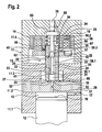
- the as a cut in the FIGS. 1 and 2 illustrated fuel injector has an injector 11 with a plurality of housing parts 11.1 to 11.4, a nozzle needle 12, a control valve 13 and a solenoid actuator 14 as an actuating element.
- the nozzle needle 12 belongs to a known injection valve member, is injected via the fuel into the combustion chamber of an internal combustion engine.
- the fuel is provided via a fuel high-pressure accumulator, not shown, (common rail) of a diesel injection device.
- the nozzle needle 12 is guided and a hydraulic control chamber 15 is formed, wherein the nozzle needle 12 is exposed to the control chamber 15 with a pressure surface 16.
- a control room 15 leads a Inlet bore 17 with an inlet throttle, wherein the inlet bore 17 is connected to a high pressure port of the high-pressure fuel storage, not shown.
- the control valve 13 has a valve sleeve 20 with a plate-shaped armature 22 and a through hole 23.
- the valve sleeve 20 is guided hydraulically tight in a guide bore 24 in the housing part 11.3 and is pressed by means of a valve spring 25 with an annular surface 26 against a sealing surface 27. Between annular surface 26 and sealing surface 27, a valve seat 30 is formed.
- the annular surface 26 is in the embodiment in FIG. 1 on the outside of the valve sleeve 20, so that the valve seat 30 lies on the outside of the valve sleeve 20.
- the sealing surface 27 is formed on a valve plate 29 formed by the housing part 11.2.
- the valve seat 30 separates a low-pressure-side valve chamber 31 from a high-pressure-side valve chamber 32.
- the through-bore 23 communicates hydraulically with the low-pressure-side valve chamber 31 and forms a discharge channel 41 which opens into a spring chamber 34, which in turn via a return line 35 with a low pressure, not shown - / return system is hydraulically connected.
- the high-pressure-side valve chamber 32 is hydraulically connected via a drain hole 37 with an outlet throttle to the control chamber 15.
- the valve sleeve 20 is surrounded by an armature space 33.
- a magnetic assembly comprising a magnetic coil 18 and a magnetic core 19, wherein the magnetic assembly generates the magnetic force for the armature 22.
- a stop plate 36 is disposed between the magnetic assembly and the magnet assembly-side end face of the magnet armature 22 sets a residual running gap. This residual air gap is intended to prevent the magnet armature 22 from sticking when the magnet assembly is deactivated.
- a gap before, which narrows with the armature stroke of the valve sleeve 20 until it stops with the Stop disc 36 is closed on the magnet assembly. The gap thus forms a depending on the armature stroke of the valve sleeve 20 adjustable hydraulic throttle 45.
- FIG. 1 In the embodiment in FIG. 1 is in the through hole 23 of the valve sleeve 20, an insert 38 arranged with a diameter constriction 39.
- the diameter constriction 39 forms a flow constriction 40 within the through-bore 23.
- From the diameter constriction 39 branches off a hydraulic connection 42, which opens on the outer surface of the valve sleeve 20 in the armature space 33.
- the diameter restriction 39 together with the hydraulic connection 42, forms a Venturi nozzle, the effect of which will be described later in connection with the function of the control valve 13.
- the flow constriction 40 for forming the Venturi nozzle can in the embodiment according to FIG. 1 be incorporated in the through hole 23. But it is also in FIG. 1 shown embodiment possible, namely insert the insert 38 with the diameter constriction 39 as a separate component in the through hole 23.
- FIG. 1 is the low-pressure side valve chamber 31 in the through hole 23 within the valve sleeve 20.
- the high-pressure side valve chamber 32 which is connected to the control chamber 15 via the drain hole 37 is arranged as an annular chamber outside the valve sleeve 20.
- FIG. 2 is in the through hole 23 of the valve sleeve 20, a pressure pin 51 with a control room-side end face 52 and a support surface 53 is arranged.
- the bearing surface 53 is supported on a support surface 54 serving as an abutment on the housing part 11.4.
- the pressure pin 51 is guided hydraulically tight with a cylinder portion 55 in the through hole 23.
- Subsequent to the cylinder portion 55 of the pressure pin 51 is executed with a first bolt-shaped portion 56.1 and a second bolt-shaped portion 56.2. Between the bolt-shaped sections 56.1 and 56.2 a conical section 57 is arranged.
- a first annular gap 58.1 and a second annular gap 58.2 formed between the lateral surfaces of the bolt-shaped portions 56.1 and 56.2 and the through hole 23 of the valve sleeve 20 .
- a first annular gap 58.1 and a second annular gap 58.2 formed between the annular gaps 58.1 and 58.2 between the annular gaps 58.1 and 58.2 is the conical form portion 57, which form an inverse form of a Venturi nozzle, so that a constricted annular gap 59 is formed by the conical form portion 57 between the two annular gaps 58.1 and 58.2, which forms the flow constriction 40.
- a hydraulic connection 62 which leads through the valve sleeve 20 and leads into the armature space 33, opens.
- valve seat 30 is in the embodiment in FIG. 2 the sealing annular surface 26 is ground on the inner diameter of the valve sleeve 20.
- the high-pressure side valve chamber 32 is bounded by the control-chamber-side end face 52 of the pressure pin 51
- the low-pressure side valve chamber 31 surrounds the valve sleeve 20 in the guide-free section in the vicinity of the valve seat 30 through the wall of the valve sleeve 20th Furthermore, a connecting bore 63 is guided, which connects the low-pressure side valve chamber 31 with the annular gap 58.1.
- valve sleeve 20 has an extended portion 65 which projects into the spring space 34 by means of a guide gap 66.
- the guide gap 66 forms a second hydraulic throttle 67.
- the drain hole 37 is also guided by the valve plate 19 and connects the control chamber 15 with the valve sleeve 20 formed in the high-pressure side valve chamber 42.
- the spring chamber 34 is connected via a connecting channel 69 with the return line 35.
- the Venturi nozzle is designed as an annular nozzle, wherein the pressure pin 51 inserted into the through hole 23 is shaped accordingly.
- the throttle 45 influenced by the stroke of the armature 22 is expanded by the permanent throttle 67. In this way, the refilling of the armature space 33 can be delayed.
- the valve sleeve 20 is pressure balanced, because the low-pressure side valve chamber 31 is hydraulically connected via the through hole 23 with the spring chamber connected to the low pressure 34 Thus, there is almost the same pressure level at the bottom and at the top of the valve sleeve 20.
- the diameter of the spring chamber 34 is slightly larger than the outer diameter of the valve sleeve 20 in order to compensate for the pressure loss via the flow constriction 40.
- the static hydraulic pressure in the through-bore 23 is greatly reduced, so that a negative pressure is created at the narrowest point due to the greater flow velocity, which supplies fuel from the armature space 33 via the hydraulic connections 42, 62 sucks, causing the armature space 33 is almost evacuated.
- the suction is facilitated by the fact that the armature 22 strikes against the magnet assembly when opening, whereby the armature space 33 is hydraulically decoupled from the spring chamber 34, which is permanently connected to the return line 35.
- the armature space 33 can not be refilled from the low pressure / return system thereby.
- valve sleeve 20 When the solenoid actuator 14 is deactivated, the magnetic force collapses and the valve sleeve 20 is returned to the valve seat 30 by the valve spring 25. With increasing stroke of the valve sleeve 20, the throttle 45 is opened between armature 22 and magnet assembly and the armature space 33 is filled again from the spring chamber 34 with fuel.
- valve sleeve 20 and the magnet armature 22 can either be made of one part or the magnet armature 22 is pressed or riveted onto the valve sleeve 20.
- the armature stroke is limited by the magnet assembly, or via the stop plate 36.
- the residual air gap is adjusted with the stop disc 36, which consists of a non-magnetic material. But it is equally possible to dispense with the stopper plate 36 and instead to provide the magnet assembly-side end face of the magnet armature 22 with a chromium layer.
Landscapes
- Engineering & Computer Science (AREA)
- Chemical & Material Sciences (AREA)
- Combustion & Propulsion (AREA)
- Mechanical Engineering (AREA)
- General Engineering & Computer Science (AREA)
- Physics & Mathematics (AREA)
- Fluid Mechanics (AREA)
- Fuel-Injection Apparatus (AREA)
Description
- Die Erfindung betrifft ein kraftausgeglichenes Steuerventil für einen Kraftstoffinjektor mit den Merkmalen des Oberbegriffs des Anspruchs 1.
- Servogesteuerte Kraftstoffinjektoren für Common-Rail-Systeme mit einer im Wesentlichen leckagefreien Düsennadelseite haben aufgrund einer fehlenden Niederdruckstufe eine sehr kurze Verzögerungszeit zwischen Ansteuerung und Einspritzung. Um bei derartigen Kraftstoffinjektoren sowohl eine Nullmenge als auch ein plateaufreies Mengenkennfeld sinnvoll realisieren zu können, ist ein schnell schaltendes Magnetventil unbedingt erforderlich. Aus diesem Grunde wurden Magnetventile kraft- bzw. druckausgeglichen ausgeführt, d. h., dass der zu schaltende Raildruck keine resultierende Druckkraft auf einen Ventilkolben des Magnetventils ausübt. Der Großteil des Kraftpotentials des Magnetventils kann somit für die Dynamik zum Schalten bereitgestellt werden und muss nicht als Schließkraft für das Steuerventil vorgehalten werden.
- Magnetventile, die zur Schaltung von Servokreisläufen von Kraftstoffinjektoren eingesetzt werden, haben üblicherweise eine gewisse Niederdruckabhängigkeit. Gerade die besagten druckausgeglichenen Magnetventile operieren auf einem niedrigen statischen Kraftniveau und sind daher besonders empfindlich gegen äußere Krafteinwirkungen. Die Niederdruckabhängigkeit ist hauptsächlich durch die ausströmende Steuermenge beim Öffnen des Magnetventils begründet, die eine Druckwelle im Niederdruckkreis auslöst. Durch die Druckschwingungen entstehen vor allem an den Ankerflächen des Magnetventils große hydraulische Kräfte, die die Schaltcharakteristik stark beeinflussen. Die Entstehung, Ausbreitung und Stärke der Druckwellen in einer Zwei-Phasen-Strömung aus Gas und Luft, wie sie im Ventilraum bzw. Rücklauf vorherrscht, sind nicht-deterministisch und unterliegen starken Schwankungen. Der hohe Gasanteil im Rücklauf ist hauptsächlich durch die kavitierende Ablaufdrossel begründet.
- Aus
EP 0 781 913 A2 ist ein Kraftstoffinjektor mit einem elektromagnetischen Stellelement (Magnetaktor) bekannt, wobei ein Magnetanker mit einer Ventilhülse antriebsverbunden ist, welche axial beweglich geführt ist und mit einer Schließkraft gegen einen Ventilsitz drückt. Der Ventilsitz trennt eine niederdruckseitige Ventilkammer von einer hochdruckseitigen Ventilkammer, wobei die niederdruckseitige Ventilkammer über einen in der Ventilhülse geführten Abströmkanal permanent mit einer Rücklaufleitung hydraulisch verbunden ist. Der Magnetanker ist in einem Ankerraum angeordnet, der wiederum mit der Rücklaufleitung hydraulisch verbunden ist. Die hochdruckseitige Ventilkammer ist über eine Ablaufbohrung mit einem Steuerraum für eine Düsennadel eines Einspritzventilglieds hydraulisch verbunden. Zwischen Abströmkanal und Ankerraum ist eine hydraulische Verbindung ausgebildet. - Ein Kraftstoffinjektor mit einem kraftausgeglichenen Steuerventil, das von einem Magnetaktor betätigt wird, welches zur Steuerung des Drucks in einem hydraulischen Steuerraum dient und dazu einen Ventilkolben mit einem Flachsitz aufweist, ist aus
EP 1 639 563 A2 bekannt. Bei geöffnetem Steuerventil wird der über eine Zulaufdrossel mit einem Hochdruckanschluss in Verbindung stehende hydraulische Steuerraum mit einem Niederdruckanschluss verbunden, wodurch der Druck im hydraulischen Steuerraum abfällt. Die an einer Druckschulter der Düsennadel des Einspritzventilglieds wirkende Öffnungskraft übersteigt infolgedessen die vom Steuerraum ausgehende Schließkraft. Die Düsennadel wird von einem Düsennadelsitz abgehoben und Kraftstoff mit dem Systemdruck des Common-Rails in den Brennraum einer Brennkraftmaschine eingespritzt. - Zur Verbesserung des dynamischen Verhaltens eines kraftausgeglichenen Steuerventils wurde bereits in
DE-Patentanmeldung 102007001554.4 vorgeschlagen, die Absteuermenge aus dem hydraulischen Steuerraum über eine durch den Ventilkolben geführte axiale Bohrung und nicht über einen Ankerraum des Magnetaktors in den Niederdruckanschluss abzuleiten. - Aufgabe der vorliegenden Erfindung ist es, ein kraftausgeglichenen Steuerventil für einen Kraftstoffinjektor zu schaffen, das sich durch eine extrem hohe Robustheit und eine geringere Niederdruckabhängigkeit auszeichnet.
- Die Aufgabe der Erfindung wird mit den kennzeichnenden Maßnahmen des Anspruchs 1 gelöst.
- Über die hydraulische Verbindung wird eine Saugwirkung im Ankerraum erzeugt. Dazu ist im Abströmkanal eine Strömungsverengung ausgebildet, in welche die hydraulische Verbindung mündet.
- Dadurch, dass während des Schaltvorgangs des Magnetankers der Kraftstoff aus der Ankerraum in den Niederdruckanschluss abgesaugt wird, entsteht im Ankerraum ein niedriges Druckniveau. Aufgrund dessen wird ein hydraulisches Kleben des Magnetankers am Hubanschlag beim Schließvorgang des Luftspalts verhindert, weil im gesamten Ankerraum ein Unterdruck vorherrscht und kein Druckunterschied zwischen Ankeroberseite und Ankerunterseite auftreten kann, auch dann nicht, wenn durch die Schließbewegung am Hubanschlag in Folge eines Quetschspaltes ein Unterdruck entsteht. Zum anderen wird verhindert, dass ein durch die Absteuermenge aus dem Steuerraum bedingter Druckanstieg nur einseitig am Magnetanker vorliegt und so eine parasitäre Kraft auf den Magnetanker wirkt.
- Vorteilhafte Weiterbildungen der Erfindung sind durch die Maßnahmen der Unteransprüche möglich.
- Die Absaugung aus dem Ankerraum wird vorteilhafterweise mittels eines Wirkdruckverfahrens realisiert. Dazu weist die Strömungsverengung die Funktion einer Venturi-Düse auf, so dass aufgrund der durch die erhöhte Strömungsgeschwindigkeit in der Strömungsverengung resultierenden Druckerniedrigung ein Wirkdruck entsteht, durch den über die hydraulischen Verbindung Kraftstoff aus dem Ankerraum heraus in den Abströmkanal abgesaugt wird.
- Gemäß einer Ausführungsform des Steuerventil ist der Abströmkanal von einer in der Ventilhülse ausgebildeten Durchgangsbohrung realisiert, wobei die Strömungsverengung als Durchmesserverengung der Durchgangsbohrung ausgebildet ist. Dazu ist es auch möglich, in die Durchgangsbohrung einen Einsatz einzusetzen, in welchem die Durchmesserverengung ausgebildet ist.
- Gemäß einer weiteren Ausführungsform des Steuerventil ist der Abströmkanal von einem Ringspalt gebildet, der einen in die Durchgangsbohrung eingesetzten Druckstift umgibt. Die Strömungsverengung wird hierbei durch einen vom Druckstift gebildeten, verengten Ringspalt ausgebildet. Der Druckstift begrenzt dabei mit einer steuerraumseitigen Stirnfläche die hochdruckseitige Ventilkammer. Der Ringraum ist über eine durch die Wandung der Ventilhülse geführten Querbohrung mit der niederdruckseitigen Ventilkammer hydraulisch verbunden.
- Zweckmäßigerweise ist die Ventilhülse am Außenumfang in einer an einem Gehäuseteil ausgebildeten Führung axial beweglich geführt, wobei die Führung den Ankerraum begrenzt. Außerdem ist es zweckmäßig, wenn zwischen Magnetanker und einer Magnetbaugruppe des Stellelements eine Anschlagscheibe zur Ausbildung eines Restluftspalts angeordnet ist. Dadurch, dass die Ventilhülse eine Verlängerung aufweist, mit der die Ventilhülse in eine benachbarte Federkammer hineinragt, bildet sich zwischen Federkammer und Verlängerung eine hydraulische Drossel aus, die permanent über den gesamten Hub der Ventilhülse wirkt.
- Die Ausführungsbeispiele der Erfindung sind in der Zeichnung dargestellt und in der nachfolgenden Beschreibung näher erläutert.
- Es zeigen:
-
Figur 1 einen steuerventilseitigen Ausschnitt eines Kraftstoffinjektors gemäß einem ersten Ausführungsbeispiel und -
Figur 2 einen steuerventilseitigen Ausschnitt eines Kraftstoffinjektors gemäß einem zweiten Ausführungsbeispiel. - Der als Ausschnitt in den
Figuren 1 und2 dargestellte Kraftstoffinjektor weist ein Injektorgehäuse 11 mit mehrerer Gehäuseteile 11.1 bis 11.4, eine Düsennadel 12, ein Steuerventil 13 und ein Magnetaktor 14 als Stellelement auf. Die Düsennadel 12 gehört zu einem an sich bekannten Einspritzventilglied, über das Kraftstoff in den Brennraum einer Brennkraftmaschine eingespritzt wird. Der Kraftstoff wird dabei über einen nicht dargestellten Kraftstoff-Hochdruckspeicher (Common-Rail) einer Dieseleinspritzeinrichtung bereitgestellt. - Im Gehäuseteil 11.1 ist die Düsennadel 12 geführt und ein hydraulischer Steuerraum 15 ausgebildet, wobei die Düsennadel 12 mit einer Druckfläche 16 dem Steuerraum 15 ausgesetzt ist. In den Steuerraum 15 führt eine Zulaufbohrung 17 mit einer Zulaufdrossel, wobei die Zulaufbohrung 17 an einen nicht dargestellten Hochdruckanschluss des Kraftstoff-Hochdruckspeichers angeschlossen ist.
- Das Steuerventil 13 weist eine Ventilhülse 20 mit einem tellerförmigen Magnetanker 22 und einer Durchgangsbohrung 23 auf. Die Ventilhülse 20 ist in einer Führungsbohrung 24 im Gehäuseteil 11.3 hydraulisch dicht geführt und wird mittels einer Ventilfeder 25 mit einer Ringfläche 26 gegen eine Dichtfläche 27 gedrückt. Zwischen Ringfläche 26 und Dichtfläche 27 bildet sich ein Ventilsitz 30 aus. Die Ringfläche 26 ist beim Ausführungsbeispiel in
Figur 1 an der Ventilhülse 20 außen eingeschliffen, so dass der Ventilsitz 30 außen an der Ventilhülse 20 liegt. Die Dichtfläche 27 ist an einer vom Gehäuseteil 11.2 ausgebildeten Ventilplatte 29 ausgebildet. - Der Ventilsitz 30 trennt eine niederdruckseitige Ventilkammer 31 von einer hochdruckseitigen Ventilkammer 32. Die Durchgangsbohrung 23 steht mit der niederdruckseitigen Ventilkammer 31 hydraulisch in Verbindung und bildet einen Abströmkanal 41, der in einen Federraum 34 mündet, der wiederum über eine Rücklaufleitung 35 mit einem nicht dargestellten Niederdruck-/Rücklaufsystem hydraulisch verbunden ist. Die hochdruckseitige Ventilkammer 32 ist über eine Ablaufbohrung 37 mit einer Ablaufdrossel mit dem Steuerraum 15 hydraulisch verbunden. Am tellerförmigen Magnetanker 22 ist die Ventilhülse 20 von einem Ankerraum 33 umgeben.
- Im Gehäuseteil 11.4 ist der Magnetaktor 14 mit eine Magnetbaugruppe angeordnet, die eine Magnetspule 18 und einen Magnetkern 19 umfasst, wobei die Magnetbaugruppe die Magnetkraft für den Magnetanker 22 erzeugt An der magnetbaugruppenseitigen Stirnfläche des Magnetankers 22 ist eine Anschlagscheibe 36 angeordnet, die zwischen der Magnetbaugruppe und der magnetbaugruppenseitigen Stirnfläche des Magnetankers 22 einen Restlaufspalt einstellt. Dieser Restluftspalt soll verhindern, dass der Magnetanker 22 bei Deaktivieren der Magnetbaugruppe kleben bleibt. Zwischen der magentankerseitigen Stirnfläche der Magnetbaugruppe und der Anschlagscheibe 36 liegt im geschlossenen Zustand des Ventilsitzes 30 ein Spalt vor, der sich mit dem Ankerhub der Ventilhülse 20 verengt bis er mit dem Anschlagen der Anschlagscheibe 36 an der Magnetbaugruppe geschlossen ist. Der Spalt bildet somit eine in Abhängigkeit vom Ankerhub der Ventilhülse 20 verstellbare hydraulische Drossel 45 aus.
- Beim Ausführungsbeispiel in
Figur 1 ist in die Durchgangsbohrung 23 der Ventilhülse 20 ein Einsatz 38 mit einer Durchmesserverengung 39 angeordnet. Die Durchmesserverengung 39 bildet innerhalb der Durchgangsbohrung 23 einen Strömungsverengung 40 aus. Von der Durchmesserverengung 39 zweigt eine hydraulischen Verbindung 42 ab, die an der Außenfläche der Ventilhülse 20 in den Ankerraum 33 mündet. Die Durchmesserverengung 39 bildet zusammen mit der hydraulischen Verbindung 42 eine Venturi-Düse, deren Wirkung später im Zusammenhang mit der Funktion des Steuerventils 13 beschrieben wird. Die Strömungsverengung 40 zur Ausbildung der Venturi-Düse kann beim Ausführungsbeispiel gemäßFigur 1 in der Durchgangsbohrung 23 eingearbeitet sein. Es ist aber auch die inFigur 1 gezeigt Ausführung möglich, nämlich den Einsatz 38 mit der Durchmesserverengung 39 als separates Bauteil in die Durchgangsbohrung 23 einzusetzen. - Beim Ausführungsbeispiel gemäß
Figur 1 befindet sich die niederdruckseitige Ventilkammer 31 in der Durchgangsbohrung 23 innerhalb der Ventilhülse 20. Die hochdruckseitige Ventilkammer 32, die mit dem Steuerraum 15 über die Ablaufbohrung 37 verbunden ist, ist als Ringkammer außerhalb der Ventilhülse 20 angeordnet. - Beim Ausführungsbeispiel gemäß
Figur 2 ist in der Durchgangsbohrung 23 der Ventilhülse 20 ein Druckstift 51 mit einer steuerraumseitigen Stirnfläche 52 und einer Auflagefläche 53 angeordnet. Die Auflagefläche 53 stützt sich an einer als Widerlager dienenden Stützfläche 54 am Gehäuseteil 11.4 ab. Der Druckstift 51 ist mit einem Zylinderabschnitt 55 in der Durchgangsbohrung 23 hydraulisch dicht geführt. Anschließend an den Zylinderabschnitt 55 ist der Druckstift 51 mit einem ersten bolzenförmigen Abschnitt 56.1 und einem zweiten bolzenförmigen Abschnitt 56.2 ausgeführt. Zwischen den bolzenförmigen Abschnitten 56.1 und 56.2 ist eine Kegelformabschnitt 57 angeordnet. Außerdem ist zwischen den Mantelflächen der bolzenförmigen Abschnitte 56.1 und 56.2 und der Durchgangsbohrung 23 der Ventilhülse 20 ein erster Ringspalt 58.1 und ein zweiter Ringspalt 58.2 ausgebildet. Zwischen den Ringspalten 58.1 und 58.2 befindet sich der Kegelformabschnitt 57, der eine inverse Form einer Venturi-Düse bilden, so dass durch den Kegelformabschnitt 57 zwischen den beiden Ringspalten 58.1 und 58.2 ein verengter Ringspalt 59 entsteht, der die Strömungsverengung 40 ausbildet. Im Bereich des verengten Ringspalts 59 mündet eine durch die Ventilhülse 20 geführte hydraulische Verbindung 62, die in den Ankerraum 33 führt. - Zur Ausbildung des Ventilsitzes 30 ist beim Ausführungsbeispiel in
Figur 2 die dichtende Ringfläche 26 am Innendurchmesser der Ventilhülse 20 eingeschliffen. Im Unterschied zum Ausführungsbeispiel inFigur 1 ist die hochdruckseitige Ventilkammer 32 innerhalb der Ventilhülse 20 ausgebildet Die hochdruckseitige Ventilkammer 32 wird von der steuerraumseitigen Stirnfläche 52 des Druckstiftes 51 begrenzt Die niederdruckseitige Ventilkammer 31 umgibt von außen die Ventilhülse 20 im führungsfreien Abschnitt in der Nähe des Ventilsitzes 30. Durch die Wandung der Ventilhülse 20 ist weiterhin eine Verbindungsbohrung 63 geführt, die die niederdruckseitige Ventilkammer 31 mit dem Ringspalt 58.1 verbindet. - Das Ausführungsbeispiel in
Figur 2 unterscheidet sich weiterhin vom Ausführungsbeispiel inFigur 1 dadurch, dass die Ventilhülse 20 einen verlängerten Abschnitt 65 aufweist, der in den Federraum 34 mittels eines Führungsspalts 66 hineinragt. Der Führungsspalt 66 bildet eine zweite hydraulischen Drossel 67 aus. Die Ablaufbohrung 37 ist ebenfalls durch die Ventilplatte 19 geführt und verbindet den Steuerraum 15 mit der innerhalb der Ventilhülse 20 ausgebildeten hochdruckseitigen Ventilkammer 42. Außerdem ist beim Ausführungsbeispiel inFigur 2 der Federraum 34 über einen Verbindungskanal 69 mit der Rücklaufleitung 35 verbunden. - Beim Ausführungsbeispiel gemäß
Figur 2 ist die Venturi-Düse als Ringdüse ausgeführt, wobei der in die Durchgangsbohrung 23 eingesetzte Druckstift 51 entsprechend geformt ist. Zusätzlich ist die vom Hub des Magnetankers 22 beeinflusste Drossel 45 durch die permanente Drossel 67 erweitert. Auf diese Weise kann die Rückbefüllung des Ankerraums 33 verzögert werden. - Beim Kraftstoffinjektor gemäß
Figur 1 und2 wird durch Betätigung des Magnetaktors 14 der Magnetankers 22 mit der Ventilhülse 20 mit Hilfe der Magnetkraft der Magnetbaugruppe vom Ventilsitz 30 abgehoben. Dadurch wird die hochdruckseitige Ventilkammer 32 mit der niederdruckseitigen Ventilkammer 31 hydraulisch verbunden. Da die niederdruckseitige Ventilkammer 31 permanent mit der Rücklaufleitung 35 in Verbindung steht, wird bei geöffnetem Ventilsitz 30 über die Ablaufbohrung 37 auch der Steuerraumdruck entlastet Dadurch entsteht an einer nicht dargestellten Druckschulter eine in Öffnungsrichtung wirkende Öffnungskraft an der Düsenadel 12, die größer ist als die im Steuerraum 15 wirkende Schließkraft. Die Düsennadel 12 wird geöffnet und dadurch Kraftstoff mit dem vom Kraftstoff-Hochdruckspeicher bereitgestellten Systemdruck in die Brennkammer der Brennkraftmaschine eingespritzt. - Auch im geöffneten Zustand ist die Ventilhülse 20 druckausgeglichen, weil die niederdruckseitige Ventilkammer 31 über die Durchgangsbohrung 23 mit dem an den Niederdruck angeschlossenen Federraum 34 hydraulisch verbunden ist Somit liegt an der Unterseite und an der Oberseite der Ventilhülse 20 nahezu das gleiche Druckniveau vor. Vorteilhafterweise ist der Durchmesser des Federraums 34 etwas größer als der Außendurchmesser der Ventilhülse 20, um den Druckverlust über die Strömungsverengung 40 auszugleichen.
- Durch die nach dem Venturi-Düsen-Prinzip arbeitende Strömungsverengung 40 wird der statische Hydraulikdruck in der Durchgangsbohrung 23 stark reduziert, so dass aufgrund der größeren Strömungsgeschwindigkeit an der engsten Stelle ein Unterdruck entsteht, der über die hydraulischen Verbindungen 42, 62 Kraftstoff aus dem Ankerraum 33 absaugt, wodurch der Ankerraum 33 nahezu evakuiert wird. Die Absaugung wird dadurch begünstigt, dass der Magnetanker 22 beim Öffnen an die Magnetbaugruppe anschlägt, wodurch der Ankerraum 33 vom Federraum 34, der permanent mit dem Rücklauf 35 verbunden ist, hydraulisch abgekoppelt wird. Der Ankerraum 33 kann dadurch nicht aus dem Niederdruck-/Rücklaufsystem rückbefüllt werden. Durch die Absaugung und die hydraulische Abkopplung des Ankerraums 33 vom Federraum 34 wird ein Druckunterschied an der oberen und unteren Stirnfläche des tellerförmigen Magnetankers 22, der entweder durch die abströmende Steuermenge oder ein hydraulisches Kleben begründet ist, vermieden.
- Wird der Magnetaktor 14 deaktiviert, bricht die Magnetkraft zusammen und die Ventilhülse 20 wird durch die Ventilfeder 25 wieder in den Ventilsitz 30 gestellt. Mit zunehmenden Hub der Ventilhülse 20 wird die Drossel 45 zwischen Magnetanker 22 und Magnetbaugruppe geöffnet und der Ankerraum 33 wird wieder aus dem Federraum 34 mit Kraftstoff befüllt.
- Die Ventilhülse 20 und der Magnetanker 22 können entweder aus einem Teil gefertigt werden oder der Magnetanker 22 wird auf die Ventilhülse 20 aufgepresst bzw. aufgenietet. Der Ankerhub wird über die Magnetbaugruppe, bzw. über die Anschlagscheibe 36 begrenzt. Der Restluftspalt wird mit der Anschlagscheibe 36 eingestellt, die aus einen nichtmagnetischen Material besteht. Es ist aber genauso möglich, auf die Anschlagscheibe 36 zu verzichten und anstelle dessen die magnetbaugruppenseitige Stirnfläche des Magnetankers 22 mit einer Chromschicht zu versehen.
Claims (9)
- Steuerventil für einen Kraftstoffinjektor, mit einer Ventilhülse (20), die axial beweglich geführt ist und mit einer Schließkraft gegen einen Ventilsitz (30) drückt, wobei die Ventilhülse (20) von einem elektromagnetischen Stellelement (14) betätigbar ist, wobei der Ventilsitz (30) eine niederdruckseitige Ventilkammer (31) von einer hochdruckseitigen Ventilkammer (32) trennt, wobei die niederdruckseitige Ventilkammer (31) über einen Abströmkanal (41) permanent mit einer Rücklaufleitung (35) hydraulisch verbunden ist, wobei die Ventilhülse (30) einen Magnetanker (22) aufweist, der in einem Ankerraum (33) angeordnet ist, der wiederum mit der Rücklaufleitung (35) hydraulisch verbunden ist, wobei die hochdruckseitige Ventilkammer (32) über eine Ablaufbohrung (37) mit einem Steuerraum (20) für eine Düsennadel (12) eines Einspritzventilglieds hydraulisch verbunden ist, und wobei zwischen Abströmkanal (41) und Ankerraum (33) eine hydraulische Verbindung (42, 62) ausgebildet ist, dadurch gekennzeichnet, dass der Abströmkanal (41) eine Strömungsverengung (40) aufweist, in welche die hydraulische Verbindung (42, 62) mündet.
- Steuerventil nach Anspruch 1, dadurch gekennzeichnet, dass die Strömungsverengung (40) die Funktion einer Venturi-Düse ausbildet, so dass ein Wirkdruck entsteht, durch den über die hydraulische Verbindung (42, 62) Kraftstoff aus dem Ankerraum (33) heraus in den Abströmkanal (41) abgesaugt wird.
- Steuerventil nach Anspruch 1 oder 2, dadurch gekennzeichnet, dass der Abströmkanal (41) von einer in der Ventilhülse (20) ausgebildeten Durchgangsbohrung (23) realisiert ist, und dass die Strömungsverengung (40) durch eine in der Durchgangsbohrung (23) ausgebildeten Durchmesserverengung (39) ausgeführt ist.
- Steuerventil nach Anspruch 3 ,dadurch gekennzeichnet, dass in die Durchgangsbohrung (23) ein Einsatz (38) mit der Durchmesserverengung (39) eingesetzt ist.
- Steuerventil nach Anspruch 1 oder 2, dadurch gekennzeichnet, dass der Abströmkanal (41) von einem Ringspalt (58.1, 58.2) gebildet ist, der einen in eine Durchgangsbohrung (23) der Ventilhülse (20) eingesetzten Druckstift (51) umgibt, und dass die Strömungsverengung (40) durch einen vom Druckstift (51) ausgebildeten verengten Ringspalt (59) gebildet ist.
- Steuerventil nach Anspruch 5, dadurch gekennzeichnet, dass der Ringraum (58.1) über eine durch die Wandung der Ventilhülse (20) geführten Querbohrung (63) mit der niederdruckseitigen Ventilkammer (31) verbunden ist.
- Steuerventil nach einem der vorhergehenden Ansprüche, dadurch gekennzeichnet, dass die Ventilhülse (20) am Außenumfang in einer an einem Gehäuseteil ausgebildeten Führung (24) axial beweglich geführt ist, und dass die Führung (24) den Ankerraum (33) begrenzt.
- Steuerventil nach einem der vorhergehenden Ansprüche, dadurch gekennzeichnet, dass zwischen Magnetanker (22) und einer Magnetbaugruppe des Stellelements (14) eine Anschlagscheibe (45) zur Ausbildung eines Restluftspalts angeordnet ist.
- Steuerventil nach einem der vorhergehenden Ansprüche, dadurch gekennzeichnet, dass die Ventilhülse (20) eine Verlängerung (65) aufweist, mit der die Ventilhülse (20) in eine benachbarte Federkammer (34) hineinragt, so dass sich zwischen Federkammer (34) und Verlängerung (65) eine hydraulische Drossel (67) ausbildet, die permanent über den gesamten Hub der Ventilhülse (20) wirkt.
Applications Claiming Priority (1)
| Application Number | Priority Date | Filing Date | Title |
|---|---|---|---|
| DE102007058766A DE102007058766A1 (de) | 2007-12-06 | 2007-12-06 | Steuerventil für einen Kraftstoffinjektor |
Publications (2)
| Publication Number | Publication Date |
|---|---|
| EP2067980A1 EP2067980A1 (de) | 2009-06-10 |
| EP2067980B1 true EP2067980B1 (de) | 2011-02-02 |
Family
ID=40433508
Family Applications (1)
| Application Number | Title | Priority Date | Filing Date |
|---|---|---|---|
| EP08105792A Not-in-force EP2067980B1 (de) | 2007-12-06 | 2008-11-13 | Steuerventil für einen Kraftstoffinjektor |
Country Status (3)
| Country | Link |
|---|---|
| EP (1) | EP2067980B1 (de) |
| AT (1) | ATE497577T1 (de) |
| DE (2) | DE102007058766A1 (de) |
Families Citing this family (6)
| Publication number | Priority date | Publication date | Assignee | Title |
|---|---|---|---|---|
| US8729995B2 (en) | 2010-12-20 | 2014-05-20 | Caterpillar Inc. | Solenoid actuator and fuel injector using same |
| JP5310818B2 (ja) | 2011-06-14 | 2013-10-09 | 株式会社デンソー | 燃料噴射装置 |
| FR3023326B1 (fr) * | 2014-07-07 | 2016-07-01 | Delphi Int Operations Luxembourg Sarl | Injecteur de carburant |
| GB201513309D0 (en) | 2015-07-29 | 2015-09-09 | Delphi Int Operations Lux Srl | Fuel injector |
| FR3049325B1 (fr) * | 2016-03-24 | 2018-09-07 | Delphi International Operations Luxembourg S.A R.L. | Actionneur electromagnetique d'injecteur de carburant |
| DE102017103082A1 (de) | 2017-02-15 | 2018-03-15 | L'orange Gmbh | Kraftstoff-Einspritzinjektor für eine Brennkraftmaschine |
Family Cites Families (4)
| Publication number | Priority date | Publication date | Assignee | Title |
|---|---|---|---|---|
| GB9526522D0 (en) | 1995-12-23 | 1996-02-28 | Lucas Ind Plc | Valve arrangement |
| FR2857113B1 (fr) | 2003-07-01 | 2005-09-02 | Tokheim Services France | Boitier securise renfermant un clavier permettant d'introduire des donnees confidentielles |
| DE102006036446A1 (de) * | 2006-08-04 | 2008-02-07 | Robert Bosch Gmbh | Injektor für ein Kraftstoffeinspritzsystem |
| DE102007001554A1 (de) | 2007-01-10 | 2008-07-17 | Robert Bosch Gmbh | Kraftstoffinjektor |
-
2007
- 2007-12-06 DE DE102007058766A patent/DE102007058766A1/de not_active Withdrawn
-
2008
- 2008-11-13 AT AT08105792T patent/ATE497577T1/de active
- 2008-11-13 DE DE502008002520T patent/DE502008002520D1/de active Active
- 2008-11-13 EP EP08105792A patent/EP2067980B1/de not_active Not-in-force
Also Published As
| Publication number | Publication date |
|---|---|
| EP2067980A1 (de) | 2009-06-10 |
| DE102007058766A1 (de) | 2009-06-10 |
| ATE497577T1 (de) | 2011-02-15 |
| DE502008002520D1 (de) | 2011-03-17 |
Similar Documents
| Publication | Publication Date | Title |
|---|---|---|
| EP1654456B1 (de) | Kraftstoff-einspritzvorrichtung für eine brennkraftmaschine | |
| EP1332282B1 (de) | Magnetventil zur steuerung eines einspritzventils einer brennkraftmaschine | |
| EP2634413B1 (de) | Einspritzventil | |
| WO2008015039A1 (de) | Injektor für ein kraftstoffeinspritzsystem | |
| EP1234112A1 (de) | Kraftstoffeinspritzsystem für brennkraftmaschinen | |
| EP2067980A1 (de) | Steuerventil für einen Kraftstoffinjektor | |
| DE102008002527A1 (de) | Kraftstoff-Injektor | |
| EP2123898B1 (de) | Kraftstoff-Injektor | |
| DE102009045728A1 (de) | Magnetventil sowie Kraftstoff-Injektor mit einem Magnetventil | |
| WO2002073028A2 (de) | Sitz/schieber-ventil mit druckausgleichsstift | |
| EP2147206B1 (de) | Kraftstoffinjektor mit magnetventil | |
| DE102008042227A1 (de) | Kraftstoff-Injektor | |
| DE102008001602B4 (de) | Verfahren zum Ansteuern eines Steuerventils eines Kraftstoff-Injektors sowie Kraftstoff-Einspritzsystem | |
| WO2007057252A1 (de) | Kraftstoff-einspritzvorrichtung für eine brennkraftmaschine mit kraftstoff-direkteinspritzung | |
| EP2466107A1 (de) | Kraftstoffinjektor mit druckausgeglichenem Steuerventil | |
| EP1574701A1 (de) | Common-Rail Injektor | |
| EP1961953A1 (de) | Mehrwegeventil | |
| DE102019215119A1 (de) | Kraftstoffinjektor | |
| EP2229527B1 (de) | Schaltventil für injektoren | |
| EP2019198A2 (de) | Injektor | |
| WO2019154687A1 (de) | Elektromagnetisch betätigbares steuerventil für einen kraftstoffinjektor und kraftstoffinjektor | |
| EP2138709A1 (de) | Direkt betätigter Kraftstoffinjektor | |
| WO2017211485A1 (de) | Einspritzdüse | |
| DE102009029231A1 (de) | Kraftstoffinjektor | |
| DE102010040620A1 (de) | Magnetventil, insbesondere für einen Kraftstoffinjektor |
Legal Events
| Date | Code | Title | Description |
|---|---|---|---|
| PUAI | Public reference made under article 153(3) epc to a published international application that has entered the european phase |
Free format text: ORIGINAL CODE: 0009012 |
|
| AK | Designated contracting states |
Kind code of ref document: A1 Designated state(s): AT BE BG CH CY CZ DE DK EE ES FI FR GB GR HR HU IE IS IT LI LT LU LV MC MT NL NO PL PT RO SE SI SK TR |
|
| AX | Request for extension of the european patent |
Extension state: AL BA MK RS |
|
| 17P | Request for examination filed |
Effective date: 20091210 |
|
| AKX | Designation fees paid |
Designated state(s): AT BE BG CH CY CZ DE DK EE ES FI FR GB GR HR HU IE IS IT LI LT LU LV MC MT NL NO PL PT RO SE SI SK TR |
|
| GRAP | Despatch of communication of intention to grant a patent |
Free format text: ORIGINAL CODE: EPIDOSNIGR1 |
|
| GRAS | Grant fee paid |
Free format text: ORIGINAL CODE: EPIDOSNIGR3 |
|
| GRAA | (expected) grant |
Free format text: ORIGINAL CODE: 0009210 |
|
| AK | Designated contracting states |
Kind code of ref document: B1 Designated state(s): AT BE BG CH CY CZ DE DK EE ES FI FR GB GR HR HU IE IS IT LI LT LU LV MC MT NL NO PL PT RO SE SI SK TR |
|
| REG | Reference to a national code |
Ref country code: GB Ref legal event code: FG4D Free format text: NOT ENGLISH |
|
| REG | Reference to a national code |
Ref country code: CH Ref legal event code: EP |
|
| REG | Reference to a national code |
Ref country code: IE Ref legal event code: FG4D Free format text: LANGUAGE OF EP DOCUMENT: GERMAN |
|
| REF | Corresponds to: |
Ref document number: 502008002520 Country of ref document: DE Date of ref document: 20110317 Kind code of ref document: P |
|
| REG | Reference to a national code |
Ref country code: DE Ref legal event code: R096 Ref document number: 502008002520 Country of ref document: DE Effective date: 20110317 |
|
| REG | Reference to a national code |
Ref country code: NL Ref legal event code: VDEP Effective date: 20110202 |
|
| LTIE | Lt: invalidation of european patent or patent extension |
Effective date: 20110202 |
|
| PG25 | Lapsed in a contracting state [announced via postgrant information from national office to epo] |
Ref country code: SE Free format text: LAPSE BECAUSE OF FAILURE TO SUBMIT A TRANSLATION OF THE DESCRIPTION OR TO PAY THE FEE WITHIN THE PRESCRIBED TIME-LIMIT Effective date: 20110202 Ref country code: HR Free format text: LAPSE BECAUSE OF FAILURE TO SUBMIT A TRANSLATION OF THE DESCRIPTION OR TO PAY THE FEE WITHIN THE PRESCRIBED TIME-LIMIT Effective date: 20110202 Ref country code: ES Free format text: LAPSE BECAUSE OF FAILURE TO SUBMIT A TRANSLATION OF THE DESCRIPTION OR TO PAY THE FEE WITHIN THE PRESCRIBED TIME-LIMIT Effective date: 20110513 Ref country code: GR Free format text: LAPSE BECAUSE OF FAILURE TO SUBMIT A TRANSLATION OF THE DESCRIPTION OR TO PAY THE FEE WITHIN THE PRESCRIBED TIME-LIMIT Effective date: 20110503 Ref country code: NO Free format text: LAPSE BECAUSE OF FAILURE TO SUBMIT A TRANSLATION OF THE DESCRIPTION OR TO PAY THE FEE WITHIN THE PRESCRIBED TIME-LIMIT Effective date: 20110502 Ref country code: PT Free format text: LAPSE BECAUSE OF FAILURE TO SUBMIT A TRANSLATION OF THE DESCRIPTION OR TO PAY THE FEE WITHIN THE PRESCRIBED TIME-LIMIT Effective date: 20110602 Ref country code: LV Free format text: LAPSE BECAUSE OF FAILURE TO SUBMIT A TRANSLATION OF THE DESCRIPTION OR TO PAY THE FEE WITHIN THE PRESCRIBED TIME-LIMIT Effective date: 20110202 Ref country code: LT Free format text: LAPSE BECAUSE OF FAILURE TO SUBMIT A TRANSLATION OF THE DESCRIPTION OR TO PAY THE FEE WITHIN THE PRESCRIBED TIME-LIMIT Effective date: 20110202 Ref country code: IS Free format text: LAPSE BECAUSE OF FAILURE TO SUBMIT A TRANSLATION OF THE DESCRIPTION OR TO PAY THE FEE WITHIN THE PRESCRIBED TIME-LIMIT Effective date: 20110602 |
|
| PG25 | Lapsed in a contracting state [announced via postgrant information from national office to epo] |
Ref country code: NL Free format text: LAPSE BECAUSE OF FAILURE TO SUBMIT A TRANSLATION OF THE DESCRIPTION OR TO PAY THE FEE WITHIN THE PRESCRIBED TIME-LIMIT Effective date: 20110202 Ref country code: FI Free format text: LAPSE BECAUSE OF FAILURE TO SUBMIT A TRANSLATION OF THE DESCRIPTION OR TO PAY THE FEE WITHIN THE PRESCRIBED TIME-LIMIT Effective date: 20110202 Ref country code: BG Free format text: LAPSE BECAUSE OF FAILURE TO SUBMIT A TRANSLATION OF THE DESCRIPTION OR TO PAY THE FEE WITHIN THE PRESCRIBED TIME-LIMIT Effective date: 20110502 Ref country code: SI Free format text: LAPSE BECAUSE OF FAILURE TO SUBMIT A TRANSLATION OF THE DESCRIPTION OR TO PAY THE FEE WITHIN THE PRESCRIBED TIME-LIMIT Effective date: 20110202 Ref country code: CY Free format text: LAPSE BECAUSE OF FAILURE TO SUBMIT A TRANSLATION OF THE DESCRIPTION OR TO PAY THE FEE WITHIN THE PRESCRIBED TIME-LIMIT Effective date: 20110202 Ref country code: PL Free format text: LAPSE BECAUSE OF FAILURE TO SUBMIT A TRANSLATION OF THE DESCRIPTION OR TO PAY THE FEE WITHIN THE PRESCRIBED TIME-LIMIT Effective date: 20110202 |
|
| REG | Reference to a national code |
Ref country code: IE Ref legal event code: FD4D |
|
| PG25 | Lapsed in a contracting state [announced via postgrant information from national office to epo] |
Ref country code: DK Free format text: LAPSE BECAUSE OF FAILURE TO SUBMIT A TRANSLATION OF THE DESCRIPTION OR TO PAY THE FEE WITHIN THE PRESCRIBED TIME-LIMIT Effective date: 20110202 Ref country code: IE Free format text: LAPSE BECAUSE OF FAILURE TO SUBMIT A TRANSLATION OF THE DESCRIPTION OR TO PAY THE FEE WITHIN THE PRESCRIBED TIME-LIMIT Effective date: 20110202 Ref country code: EE Free format text: LAPSE BECAUSE OF FAILURE TO SUBMIT A TRANSLATION OF THE DESCRIPTION OR TO PAY THE FEE WITHIN THE PRESCRIBED TIME-LIMIT Effective date: 20110202 |
|
| PG25 | Lapsed in a contracting state [announced via postgrant information from national office to epo] |
Ref country code: RO Free format text: LAPSE BECAUSE OF FAILURE TO SUBMIT A TRANSLATION OF THE DESCRIPTION OR TO PAY THE FEE WITHIN THE PRESCRIBED TIME-LIMIT Effective date: 20110202 Ref country code: SK Free format text: LAPSE BECAUSE OF FAILURE TO SUBMIT A TRANSLATION OF THE DESCRIPTION OR TO PAY THE FEE WITHIN THE PRESCRIBED TIME-LIMIT Effective date: 20110202 Ref country code: CZ Free format text: LAPSE BECAUSE OF FAILURE TO SUBMIT A TRANSLATION OF THE DESCRIPTION OR TO PAY THE FEE WITHIN THE PRESCRIBED TIME-LIMIT Effective date: 20110202 |
|
| PLBE | No opposition filed within time limit |
Free format text: ORIGINAL CODE: 0009261 |
|
| STAA | Information on the status of an ep patent application or granted ep patent |
Free format text: STATUS: NO OPPOSITION FILED WITHIN TIME LIMIT |
|
| 26N | No opposition filed |
Effective date: 20111103 |
|
| REG | Reference to a national code |
Ref country code: DE Ref legal event code: R097 Ref document number: 502008002520 Country of ref document: DE Effective date: 20111103 |
|
| BERE | Be: lapsed |
Owner name: ROBERT BOSCH G.M.B.H. Effective date: 20111130 |
|
| PG25 | Lapsed in a contracting state [announced via postgrant information from national office to epo] |
Ref country code: IT Free format text: LAPSE BECAUSE OF FAILURE TO SUBMIT A TRANSLATION OF THE DESCRIPTION OR TO PAY THE FEE WITHIN THE PRESCRIBED TIME-LIMIT Effective date: 20110202 |
|
| PG25 | Lapsed in a contracting state [announced via postgrant information from national office to epo] |
Ref country code: MC Free format text: LAPSE BECAUSE OF NON-PAYMENT OF DUE FEES Effective date: 20111130 |
|
| REG | Reference to a national code |
Ref country code: FR Ref legal event code: ST Effective date: 20120731 |
|
| PG25 | Lapsed in a contracting state [announced via postgrant information from national office to epo] |
Ref country code: BE Free format text: LAPSE BECAUSE OF NON-PAYMENT OF DUE FEES Effective date: 20111130 |
|
| PG25 | Lapsed in a contracting state [announced via postgrant information from national office to epo] |
Ref country code: FR Free format text: LAPSE BECAUSE OF NON-PAYMENT OF DUE FEES Effective date: 20111130 |
|
| PG25 | Lapsed in a contracting state [announced via postgrant information from national office to epo] |
Ref country code: MT Free format text: LAPSE BECAUSE OF FAILURE TO SUBMIT A TRANSLATION OF THE DESCRIPTION OR TO PAY THE FEE WITHIN THE PRESCRIBED TIME-LIMIT Effective date: 20110202 |
|
| PG25 | Lapsed in a contracting state [announced via postgrant information from national office to epo] |
Ref country code: LU Free format text: LAPSE BECAUSE OF NON-PAYMENT OF DUE FEES Effective date: 20111113 |
|
| REG | Reference to a national code |
Ref country code: CH Ref legal event code: PL |
|
| GBPC | Gb: european patent ceased through non-payment of renewal fee |
Effective date: 20121113 |
|
| PG25 | Lapsed in a contracting state [announced via postgrant information from national office to epo] |
Ref country code: LI Free format text: LAPSE BECAUSE OF NON-PAYMENT OF DUE FEES Effective date: 20121130 Ref country code: CH Free format text: LAPSE BECAUSE OF NON-PAYMENT OF DUE FEES Effective date: 20121130 |
|
| PG25 | Lapsed in a contracting state [announced via postgrant information from national office to epo] |
Ref country code: TR Free format text: LAPSE BECAUSE OF FAILURE TO SUBMIT A TRANSLATION OF THE DESCRIPTION OR TO PAY THE FEE WITHIN THE PRESCRIBED TIME-LIMIT Effective date: 20110202 |
|
| PG25 | Lapsed in a contracting state [announced via postgrant information from national office to epo] |
Ref country code: HU Free format text: LAPSE BECAUSE OF FAILURE TO SUBMIT A TRANSLATION OF THE DESCRIPTION OR TO PAY THE FEE WITHIN THE PRESCRIBED TIME-LIMIT Effective date: 20110202 |
|
| PG25 | Lapsed in a contracting state [announced via postgrant information from national office to epo] |
Ref country code: GB Free format text: LAPSE BECAUSE OF NON-PAYMENT OF DUE FEES Effective date: 20121113 |
|
| REG | Reference to a national code |
Ref country code: AT Ref legal event code: MM01 Ref document number: 497577 Country of ref document: AT Kind code of ref document: T Effective date: 20131113 |
|
| PG25 | Lapsed in a contracting state [announced via postgrant information from national office to epo] |
Ref country code: AT Free format text: LAPSE BECAUSE OF NON-PAYMENT OF DUE FEES Effective date: 20131113 |
|
| PGFP | Annual fee paid to national office [announced via postgrant information from national office to epo] |
Ref country code: DE Payment date: 20190124 Year of fee payment: 11 |
|
| REG | Reference to a national code |
Ref country code: DE Ref legal event code: R119 Ref document number: 502008002520 Country of ref document: DE |
|
| PG25 | Lapsed in a contracting state [announced via postgrant information from national office to epo] |
Ref country code: DE Free format text: LAPSE BECAUSE OF NON-PAYMENT OF DUE FEES Effective date: 20200603 |