EP2067984A2 - Anlasser mit zwei Planetengetriebedrehzahlminderern mit unterschiedlichen Drehzahlminderungsverhältnissen - Google Patents
Anlasser mit zwei Planetengetriebedrehzahlminderern mit unterschiedlichen Drehzahlminderungsverhältnissen Download PDFInfo
- Publication number
- EP2067984A2 EP2067984A2 EP08020899A EP08020899A EP2067984A2 EP 2067984 A2 EP2067984 A2 EP 2067984A2 EP 08020899 A EP08020899 A EP 08020899A EP 08020899 A EP08020899 A EP 08020899A EP 2067984 A2 EP2067984 A2 EP 2067984A2
- Authority
- EP
- European Patent Office
- Prior art keywords
- gear
- internal gear
- engaging member
- starter
- concave
- Prior art date
- Legal status (The legal status is an assumption and is not a legal conclusion. Google has not performed a legal analysis and makes no representation as to the accuracy of the status listed.)
- Granted
Links
- 239000007858 starting material Substances 0.000 title claims abstract description 85
- 230000009467 reduction Effects 0.000 title claims abstract description 77
- 239000003638 chemical reducing agent Substances 0.000 title claims abstract description 72
- 229910001285 shape-memory alloy Inorganic materials 0.000 claims abstract description 12
- 239000000463 material Substances 0.000 claims abstract description 6
- 230000033001 locomotion Effects 0.000 claims description 53
- 230000035939 shock Effects 0.000 claims description 35
- 239000006096 absorbing agent Substances 0.000 claims description 25
- 230000006870 function Effects 0.000 claims description 8
- 230000001419 dependent effect Effects 0.000 claims description 2
- 230000004323 axial length Effects 0.000 description 7
- 230000002829 reductive effect Effects 0.000 description 5
- 230000005540 biological transmission Effects 0.000 description 4
- 230000003247 decreasing effect Effects 0.000 description 4
- 238000004904 shortening Methods 0.000 description 3
- 230000007423 decrease Effects 0.000 description 2
- 238000000034 method Methods 0.000 description 2
- 239000011347 resin Substances 0.000 description 2
- 229920005989 resin Polymers 0.000 description 2
- 230000000284 resting effect Effects 0.000 description 2
- 229910000990 Ni alloy Inorganic materials 0.000 description 1
- 229910001069 Ti alloy Inorganic materials 0.000 description 1
- RTAQQCXQSZGOHL-UHFFFAOYSA-N Titanium Chemical compound [Ti] RTAQQCXQSZGOHL-UHFFFAOYSA-N 0.000 description 1
- 230000008859 change Effects 0.000 description 1
- 238000002485 combustion reaction Methods 0.000 description 1
- 230000007797 corrosion Effects 0.000 description 1
- 238000005260 corrosion Methods 0.000 description 1
- 230000002401 inhibitory effect Effects 0.000 description 1
- 230000002452 interceptive effect Effects 0.000 description 1
- 238000004519 manufacturing process Methods 0.000 description 1
- 230000003446 memory effect Effects 0.000 description 1
- 238000012986 modification Methods 0.000 description 1
- 230000004048 modification Effects 0.000 description 1
- 125000006850 spacer group Chemical group 0.000 description 1
- 239000010936 titanium Substances 0.000 description 1
Images





Classifications
-
- F—MECHANICAL ENGINEERING; LIGHTING; HEATING; WEAPONS; BLASTING
- F02—COMBUSTION ENGINES; HOT-GAS OR COMBUSTION-PRODUCT ENGINE PLANTS
- F02N—STARTING OF COMBUSTION ENGINES; STARTING AIDS FOR SUCH ENGINES, NOT OTHERWISE PROVIDED FOR
- F02N15/00—Other power-operated starting apparatus; Component parts, details, or accessories, not provided for in, or of interest apart from groups F02N5/00 - F02N13/00
- F02N15/02—Gearing between starting-engines and started engines; Engagement or disengagement thereof
- F02N15/04—Gearing between starting-engines and started engines; Engagement or disengagement thereof the gearing including disengaging toothed gears
- F02N15/043—Gearing between starting-engines and started engines; Engagement or disengagement thereof the gearing including disengaging toothed gears the gearing including a speed reducer
- F02N15/046—Gearing between starting-engines and started engines; Engagement or disengagement thereof the gearing including disengaging toothed gears the gearing including a speed reducer of the planetary type
-
- F—MECHANICAL ENGINEERING; LIGHTING; HEATING; WEAPONS; BLASTING
- F02—COMBUSTION ENGINES; HOT-GAS OR COMBUSTION-PRODUCT ENGINE PLANTS
- F02N—STARTING OF COMBUSTION ENGINES; STARTING AIDS FOR SUCH ENGINES, NOT OTHERWISE PROVIDED FOR
- F02N11/00—Starting of engines by means of electric motors
-
- F—MECHANICAL ENGINEERING; LIGHTING; HEATING; WEAPONS; BLASTING
- F02—COMBUSTION ENGINES; HOT-GAS OR COMBUSTION-PRODUCT ENGINE PLANTS
- F02N—STARTING OF COMBUSTION ENGINES; STARTING AIDS FOR SUCH ENGINES, NOT OTHERWISE PROVIDED FOR
- F02N15/00—Other power-operated starting apparatus; Component parts, details, or accessories, not provided for in, or of interest apart from groups F02N5/00 - F02N13/00
- F02N15/02—Gearing between starting-engines and started engines; Engagement or disengagement thereof
- F02N15/04—Gearing between starting-engines and started engines; Engagement or disengagement thereof the gearing including disengaging toothed gears
- F02N15/06—Gearing between starting-engines and started engines; Engagement or disengagement thereof the gearing including disengaging toothed gears the toothed gears being moved by axial displacement
- F02N15/062—Starter drives
- F02N15/063—Starter drives with resilient shock absorbers
Definitions
- the present invention relates to a starter for starting an engine of a motor vehicle which includes two planetary speed reducers with different speed reduction ratios.
- a conventional starter for starting an engine of a motor vehicle such as the one disclosed in Japanese Patent First Publication No. S61-28756 , includes a planetary (or epicyclic) speed reducer that reduces the rotational speed of a motor into the rotational speed of an output shaft of the starter at a fixed speed reduction ratio.
- the fixed speed reduction ratio is generally set based on the torque required to start the engine at the lowest operating temperature (e.g., about -20°C), at which the engine friction is largest. Therefore, when the starter starts the engine at normal operating temperatures, at which the engine friction is smaller and thus the torque required to start the engine is also smaller, the operating point on the performance curve of the motor is shifted toward the low-load side. Consequently, the output power of the motor is decreased, so that the speed of the motor cannot greatly increase.
- the lowest operating temperature e.g., about -20°C
- the time required to start the engine decreases with increase in the output speed (i.e., the speed after the speed reduction by the planetary speed reducer) of the starter.
- the output speed i.e., the speed after the speed reduction by the planetary speed reducer
- vibration of the motor during the engine starting operation is decreased, making the driver of the vehicle more comfortable and resulting in a decreased amount of exhaust gas from the engine.
- the planetary speed reducer it is desirable to increase the output speed of the starter at normal operating temperatures by lowering the speed reduction ratio of the planetary speed reducer.
- the planetary speed reducer it is desirable for the planetary speed reducer to have two different speed reduction ratios, one for use at low operating temperatures and the other for use at normal operating temperatures.
- Japanese Patent First Publication No. S61-236951 discloses a starter which includes a planetary speed reducer with two different speed reduction ratios.
- the lower speed reduction ratio is 1 (i.e., both the input and output shafts of the speed reducer rotate at the same speed), while the higher speed reduction ratio is higher than 1 but lower than 10.
- the starter may be difficult for the starter to generate, at normal operating temperatures, sufficiently large torque to start the engine.
- the starter has a complicated structure with a large number of components, making it difficult to downsize the starter.
- Japanese Patent First Publication No. S61-282650 discloses a method of using two planetary speed reducers with different speed reduction ratios in a starter. More specifically, for selecting each time only one of the two speed reducers to function, a break band is provided in each of the speed reducers around the outer periphery of an internal gear. When the break band is fastened, rotation of the internal gear is restricted, thereby enabling the speed reducer to function. On the other hand, when the break band is loosened, the internal gear is allowed to rotate, thereby disabling the speed reducer from functioning.
- the present invention has been made in view of the above-mentioned problems.
- a starter (1) for starting an engine which includes a motor (2), an output shaft (3), a pinion gear (5), a speed reducer assembly, and a speed reduction ratio shifter (34, 36, 37).
- the motor (2) generates torque.
- the motor (2) includes an armature shaft (2b) through which the generated torque is output from the motor (2).
- the output shaft (3) is linked to the armature shaft (2b) to receive the torque generated by the motor (2).
- the pinion gear (5) is provided on the output shaft (3), and is configured to mesh with a ring gear of the engine, thereby starting the engine with the torque generated by the motor (2).
- the speed reducer assembly is connected between the armature shaft (2b) and the output shaft (3) to reduce the rotational speed of the armature shaft (2b) into the rotational speed of the output shaft (3) at a speed reduction ratio.
- the speed reducer assembly includes first and second planetary speed reducers.
- the first speed reducer (20, 24, 25, 30) has a first speed reduction ratio.
- the second speed reducer (21, 28, 29, 30) has a second speed reduction ratio that is higher than the first speed reduction ratio.
- the speed reduction ratio shifter (34, 36, 37) shifts the speed reduction ratio of the speed reducer assembly between the first and second speed reduction ratios by selectively allowing one of the first and second speed reducers to function.
- the first speed reducer includes a first internal gear (25) and is configured to function as a speed reducer only when the first internal gear (25) is restricted in rotation.
- the first internal gear (25) is disposed around the armature shaft (2b).
- the second speed reducer includes a second internal gear (29) and is configured to function as a speed reducer only when the second internal gear (29) is restricted in rotation.
- the second internal gear (29) is disposed around the armature shaft (2b) and away from the first internal gear (25) in the axial direction of the armature shaft (2b).
- the speed reduction ratio shifter includes a gear engaging member (34) and a driver (36, 37) for driving the gear engaging member (34).
- the gear engaging member (34) is configured to move in the axial direction of the armature shaft (2b) to selectively engage with one of the first and second internal gears (25, 29), thereby restricting rotation of the engaged one of the first and second internal gears (25, 29) while allowing rotation of the other.
- the driver includes a first spring (36) and a second spring (37), which are respectively disposed on opposite sides of the gear engaging member (34) in the axial direction of the armature shaft (2b), and drives the gear engaging member (34) to move in the axial direction by using the difference between restoring forces of the first and second springs (36, 37).
- the first spring (36) is made of a shape memory alloy so that the restoring force of the first spring (36) is dependent on ambient temperature.
- the second spring (37) is made of an ordinary spring material so that the restoring force of the second spring (37) is independent of the ambient temperature.
- the speed reduction ratio shifter shifts the speed reduction ratio of the speed reducer assembly to the first speed reduction ratio. Consequently, the rotational speed of the output shaft (3) can be increased, thereby shortening the time required to start the engine.
- the speed reduction ratio shifter shifts the speed reduction ratio of the speed reducer assembly to the second speed reduction ratio. Consequently, the starter (1) can reliably output the torque required to start the engine though the engine friction is large at such a low ambient temperature.
- the gear engaging member (34) is moved in the axial direction of the armature shaft (2b) only by using the difference between the restoring forces of the first and second springs (36, 37). Consequently, no electric power is needed to drive the gear engaging member (34), saving the total electric power consumption for the engine start operation. Furthermore, to restrict and allow rotation of the first and second internal gears (25, 29), the gear engaging member (34) is moved only in the axial direction of the armature shaft (2b). Consequently, without having to move the gear engaging member (34) in the radial direction of the armature shaft (2b), the radial dimension of the starter (1) can be minimized.
- the first internal gear (25) is disposed closer to the motor (2) in the axial direction of the armature shaft (2b) than the second internal gear (29).
- the first internal gear (25) has a concave-convex portion (25c) that is formed on the outer periphery of the first internal gear (25) on the side of the output shaft (3).
- the second internal gear (29) has a concave-convex portion (29d) that is formed on the outer periphery of the second internal gear (29) on the side of the motor (2).
- the gear engaging member (34) has formed, on the inner periphery thereof, a first concave-convex portion (34b) for engaging with the concave-convex portion (25c) of the first internal gear (25) and a second concave-convex portion (34b) for engaging with the concave-convex portion (29d) of the second internal gear (29).
- the driver drives the gear engaging member (34) to move toward the motor (2)
- the first concave-convex portion (34b) of the gear engaging member (34) is brought into engagement with the concave-convex portion (25c) of the first internal gear (25), thereby restricting rotation of the first internal gear (25).
- the first and second concave-convex portions (34b, 34b) of the gear engaging member (34) are integrally formed into a single concave-convex portion (32b).
- the first internal gear (25) has an axial end face on the side of the output shaft (3)
- the second internal gear (29) has an axial end face on the side of the motor (2).
- a protrusion (25a) is formed on one of the axial end faces of the first and second internal gears (25, 29), and a recess (29a) is formed in the other of the axial end faces.
- the first and second internal gears (25, 29) are so disposed as to be rotatable relative to each other with the protrusion (25a) fit in the recess (29a).
- the starter (1) further includes: a starter housing (9); a frame (12) fixed to the starter housing (9) and having a cylindrical bearing box (12a) which is formed in the inner periphery of the frame (12) and in which a bearing (13) is disposed to rotatably support the output shaft (3); a shock absorber (8) provided on the outer periphery of the cylindrical bearing box (12a) formed in the frame (12) to absorb a shock input from the engine to the starter (1); and a movement restricting member (35) that is interposed in the axial direction of the armature shaft (2b) between the frame (12) and the second internal gear (29) to restrict movement of the second internal gear (29) toward the frame (12), the movement restricting member (35) being restricted in rotation by the frame (12) via the shock absorber (8).
- the gear engaging member (34) is disposed radially outward of the movement restricting member (35) to extend in the axial direction of the armature shaft (2b).
- the gear engaging member (34) has a concave-convex portion (34c) on its inner periphery
- the movement restricting member (35) has a concave-convex portion (35b) on its outer periphery.
- the concave-convex portion (34c) of the gear engaging member (34) engages with the concave-convex portion (35b) of the movement restricting member (35), allowing relative movement between the two members (34, 35) in the axial direction of the armature shaft (2b) while restricting relative rotation between the two members (34, 35).
- the shock absorber (8) is disposed within a space formed between the outer periphery of the bearing box (12a) and the inner periphery of the movement restricting member (35).
- the shock absorber (8) includes: at least one rotatable friction plate (38) that has an outer periphery fitted to the inner periphery of the movement restricting member (35), thereby being restricted in relative rotation to the movement restricting member (35); at least one fixed friction plate (39) that is disposed to overlap with the at least one rotatable friction plate (38) in the axial direction of the armature shaft (2b) and restricted in rotation by the frame (12); and a presser (40) that is located with the rotatable and fixed friction plates (38, 39) interposed between itself and the frame (12) and presses them against the frame (12) to absorb the shock with friction between the rotatable and fixed friction plates (38, 39).
- the at least one rotatable friction plate (38) comprises a plurality of rotatable friction plates (38), and the at least one fixed friction plate (39) comprises a plurality of fixed friction plates (39).
- the plurality of rotatable friction plates (38) are alternately overlapped with the plurality of fixed friction plates (39) in the axial direction of the armature shaft (2b).
- FIGS. 1-12 One preferred embodiment of the present invention will be described hereinafter with reference to FIGS. 1-12 .
- FIG. 1 shows the overall structure of a starter 1 according to an embodiment of the invention.
- the starter 1 is designed to start an internal combustion engine of a motor vehicle.
- the starter 1 includes: a motor 2 that generates torque for starting the engine; a speed reducer assembly (to be described later) that reduces the rotational speed of the motor 2; an output shaft 3 that is driven by the motor 2 via the speed reducer assembly; a speed reduction ratio shifter (to be described later) that shifts the speed reduction ratio of the speed reducer assembly; a clutch 4 and a pinion gear 5 that are integrally provided on the output shaft 3; a shift lever 6 that shifts the clutch 4 and pinion gear 5 along the output shaft 3; a solenoid switch 7 that opens and closes main contacts (not shown) included in a power supply circuit of the motor 2 and actuates the shift lever 6; a shock absorber 8 (see FIG. 8 ) that absorbs shocks transmitted from the engine to the starter 1; and a starter housing 9 for fixing the starter 1 to the engine.
- a motor 2 that generates torque for starting the engine
- a speed reducer assembly to be described later
- an output shaft 3 that is driven by the motor 2 via the speed reduce
- the motor 2 is implemented by a commutator motor which includes an armature 2a and both a commutator (not shown) and brushes (not shown) for supplying electric power to the armature 2a.
- the armature 2a includes an armature shaft 2b via which the torque generated by the motor 2 is output.
- a front end portion of the armature shaft 2b is inserted in a recess formed in a rear end portion of the output shaft 3 and rotatably supported by the rear end portion via a bearing 10 provided in the recess.
- a rear end portion of the armature shaft 2b is rotatably supported by an end frame 11 via a bearing (not shown).
- the output shaft 3 is coaxially disposed with the armature shaft 2b.
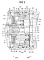
- the rear end portion of the output shaft 3 is rotatably supported, as shown in FIG. 2 , by a frame 12 via a bearing 13 that is provided in a cylindrical bearing box 12a formed in the frame 12.
- a front end portion of the output shaft 3 is rotatably supported by the starter housing 9 via a bearing 14.
- the frame 12 has a radially outer periphery fitted to the radially inner periphery of a cylindrical wall portion 9a of the starter housing 9, thereby being fixed to the starter housing 9.
- the clutch 4 is helical spline-fitted on the output shaft 3 to transmit rotation of the output shaft 3 to the pinion gear 5.
- the clutch 4 is a one-way clutch which allows torque transmission from the motor 2 to the engine while inhibiting torque transmission from the engine to the motor 2. More specifically, when the engine has started and the pinion gear 5 comes to be driven by the engine to rotate faster than the output shaft 3, the clutch 4 interrupts torque transmission from the pinion gear 5 to the output shaft 3.
- the pinion gear 5 is configured to be shifted by the shift lever 6 to mesh with a ring gear (not shown) of the engine, thereby driving the ring gear with torque that is transmitted to the pinion gear 5 via the clutch 4.
- the solenoid switch 7 includes a solenoid (not shown) and a plunger 15.
- a solenoid When the solenoid is energized by electric power from a battery (not shown) upon closing a starter switch (not shown), it creates a magnetic attraction for the plunger 15. The magnetic attraction causes the plunger 15 to move backward to close the main contacts of the power supply circuit of the motor 2. Further, when the solenoid is deenergized by interrupting the electric power supply from the battery, the magnetic attraction disappears. Then, the plunger 15 is returned forward by a return spring (not shown) to its initial position, thereby opening the main contacts of the power supply circuit of the motor 2.
- the main contacts are made up of a pair of fixed contacts (not shown) and a moving contact (not shown).
- the fixed contacts are fixed in a resin cover 7a of the solenoid switch 7, and electrically connected to the power supply circuit of the motor 2 via a pair of terminals 16 and 17 mounted on the resin cover 7a.
- the moving contact is configured to move along with the plunger 15 to connect and disconnect the fixed contacts. More specifically, when the moving contact makes contact with both the fixed contacts to connect (or bridge) the fixed contacts, the main contacts of the power supply circuit are closed. Further, when the moving contact is detached from both the fixed contacts to disconnect the fixed contacts, the main contacts are opened.
- the shift lever 6 has a fulcrum portion 6a that is rotatably held by a lever holder 18, and two opposite ends respectively on opposite sides of the fulcrum portion 6a. One of the two ends is mechanically connected to a rod 19 mounted to the plunger 15, and the other engages with the clutch 4 to transmit the motion of the plunger 15 to the clutch 4.
- the speed reducer assembly includes a first planetary speed reducer having a first sun gear 20 provided on the armature shaft 2b and a second planetary speed reducer having a second sun gear 21 provided on the armature shaft 2b.
- the first speed reducer has a lower speed reduction ratio than the second speed reducer.
- the speed reduction ratios of the first and second speed reducers are respectively referred to as first and second speed reduction ratios.
- the first sun gear 20 is located more backward than the second sun gear 21, and has both a larger tip diameter and a larger number of teeth than the second sun gear 21.
- the first speed reducer further includes a plurality of (e.g., 3 in the present embodiment) first planet gears 24 and a first internal gear (or annulus) 25.
- Each of the first planet gears 24 is rotatably supported by a planet pin 23 via a bearing 22 and meshes with the first sun gear 20.
- the first internal gear 25 is concentrically disposed with the first sun gear 20 and meshes with each of the first planet gears 24.
- the second speed reducer further includes a plurality of (e.g., 3 in the present embodiment) second planet gears 28 and a second internal gear (or annulus) 29.
- Each of the second planet gears 28 is rotatably supported by a planet pin 27 via a bearing 26 and meshes with the second sun gear 21.
- the second internal gear 29 is concentrically disposed with the second sun gear 21 and meshes with each of the second planet gears 28.
- the first and second speed reducer has a common planet carrier 30 that is formed integrally with the output shaft 3 and has both the planet pins 23 and the planet pins 27 fixed thereto. Further, the planet pins 23 are alternately arranged with the planet pins 27 in the circumferential direction of the planet carrier 30. In addition, on each of the planet pins 23, there is interposed a spacer 31 between the planet carrier 30 and a corresponding one of the first planet gears 24, thereby preventing the corresponding first planet gear 24 from moving toward the planet carrier 30.
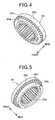
- the first internal gear 25 has, as shown in FIG.4 , an annular small-outer diameter portion 25a on the front side and an annular large-outer diameter portion 25b on the rear side.
- the first internal gear 25 further has an annular toothed portion 25c between the small-outer diameter portion 25a and the large-outer diameter portion 25b.
- the toothed portion 25c has a plurality of outer teeth formed on the outer periphery thereof over its entire circumference, and has a tip diameter of outer teeth equal to the outer diameter of the large-outer diameter portion 25b.
- the first internal gear 25 is toothed on the inner periphery thereof over its entire axial length.
- the first internal gear 25 is, as shown in FIG. 2 , concentrically disposed with the armature shaft 2b by rotatably fitting the large-outer diameter portion 25b into a hollow joint member 33; the joint member 33 is held between a yoke 32 of the motor 2 and the cylindrical wall portion 9a of the starter housing 9. In other words, the first internal gear 25 is centered by the joint member 33.
- the second internal gear 29 has, as shown in FIG. 5 , an annular small-outer diameter portion 29b on the rear side and an annular large-outer diameter portion 29c on the front side.
- the second internal gear 29 further has an annular toothed portion 29d between the small-outer diameter portion 29b and the large-outer diameter portions 29c.
- the toothed portion 29d has a plurality of outer teeth formed on the outer periphery thereof over its entire circumference, and has a tip diameter of outer teeth equal to the outer diameter of the large-outer diameter portion 29c.
- the second internal gear 29 is toothed on the inner periphery thereof only over the axial lengths of the large-outer diameter portion 29c and the toothed portion 29d.
- the inner diameter of the small-outer diameter portion 29a is made larger than the root diameter of inner teeth of the large-outer diameter portion 29c and toothed portion 29d, forming a recess 29a at the rear end of the second internal gear 29.
- the outer teeth of the toothed portion 25c of the first internal gear 25 has the same tip and root diameters as the outer teeth of the toothed portion 29d of the second internal gear 29. Further, the number of outer teeth of the toothed portion 25c of the first internal gear 25 is equal to that of the toothed portion 29d of the second internal gear 29.
- the tip diameter of the inner teeth of the first internal gear 25 is smaller than that of the inner teeth of the second internal gear 29. Further, the number of inner teeth of the first internal gear 25 is also smaller than that of the second internal gear 29.
- the outer diameter of the small-outer diameter portion 25a of the first internal gear 25 is made smaller than the inner diameter of the small-outer diameter portion 29b of the second internal gear 29, thereby allowing the small-outer diameter portion 25a of the first internal gear 25 to be rotatably fitted into the recess 29a formed in the second internal gear 29, as shown in FIG. 2 .
- the speed reduction ratio shifter includes, as shown in FIGS. 2 and 3 , a gear engaging member 34 that mechanically engages with either of the first and second internal gears 25 and 29 and a driver for driving the gear engaging member 34 to move in the axial direction of the armature shaft 2b.
- the gear engaging member 34 has a substantially hollow cylindrical shape, and is coaxially disposed with the first and second internal gears 25 and 29 to surround them.
- the gear engaging member 34 has a protruding portion 34a that protrudes radially outward from the outer periphery of the gear engaging member 34.
- the gear engaging member 34 further has first inner teeth 34b and second inner teeth 34c that are respectively formed on rear and front parts of the inner periphery of the gear engaging member 34.
- the gear engaging member 34 is centered by fitting the protruding portion 34a to the inner periphery of the cylindrical wall portion 9a of the starter housing 9, as shown in FIG. 2 .
- the gear engaging member 34 is movable in the axial direction of the armature shaft 2b, and restricted in rotation by a movement restricting member 35 interposed between the frame 12 and the second internal gear 29.
- the gear engaging member 34 When the gear engaging member 34 is moved backward to a first engagement position, as shown in FIG. 2 , the first inner teeth 34b mesh, over the rear half of the axial length thereof, with the outer teeth 25c of the first internal gear 25. In other words, in the first engagement position, the gear engaging member 34 mechanically engages with the first internal gear 25.
- the gear engaging member 34 when the gear engaging member 34 is moved forward to a second engagement position, as shown in FIG. 3 , the first inner teeth 34b mesh, over the front half of the axial length thereof, with the outer teeth 29d of the second internal gear 29. In other words, in the second engagement position, the gear engaging member 34 mechanically engages with the second internal gear 29.
- the axial length of the first inner teeth 34b is made slightly smaller than the axial space between the outer teeth 25c of the first internal gear 25 and the outer teeth 29d of the second internal gear 29. Therefore, the first inner teeth 34b of the gear engaging member 34 never concurrently mesh with both the outer teeth 25c of the first internal gear 25 and the outer teeth 29d of the second internal gear 29. In other words, the gear engaging member 34 each time engages with only one of the first and second internal gears 25 and 29.
- axial corner portions of the first inner teeth 34b of the gear engaging member 34, the outer teeth 25c of the first internal gear 25, and the outer teeth 29d of the second internal gear 29 are preferably chamfered.
- the axial length of the second inner teeth 34c of the gear engaging member 34 is made larger than that of the first inner teeth 34b. Moreover, the tip diameter of the second inner teeth 34c is made larger than the root diameter of the first inner teeth 34b, thereby preventing the second inner teeth 34c from interfering with the second internal gear 29 during the axial movement of the gear engaging member 34.
- the movement restricting member 35 has a hollow cylindrical shape, and is centered by fitting a front end portion of the member 35 onto a step portion 12b of the frame 12.
- the movement restricting member 35 has a flange portion 35a that is formed at the rear end of the member 35 to extend radially outward. On the outer periphery of the flange portion 35a, there are formed a plurality of outer teeth 35b over the entire circumference of the flange portion 35a.
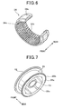
- the movement restricting member 35 further has a plurality of grooves 35c that are formed in the inner periphery of the member 35. The use of the grooves 35c will be described later.
- a rear end face of the movement restricting member 35 i.e., the rear end face of the flange portion 35a
- a front end face of the second internal gear 29 thereby restricting forward movement of the first and second internal gears 25 and 29.
- the outer teeth 35b of the movement restricting member 35 mesh with the inner teeth 34c of the gear engaging member 34, thereby restricting relative rotation between the two members 34 and 35.
- the driver for driving the gear engaging member 34 is configured with first and second springs 36 and 37 both of which are provided on the gear engaging member 34.
- the first spring 36 is made of a shape memory alloy, and located on the front side of the protruding portion 34a of the gear engaging member 34.
- the second spring 37 is made of an ordinary spring material without a shape memory effect (or without a capability of remembering its own shape), and located on the rear side of the protruding portion 34a of the gear engaging member 34.
- the shape memory alloy may be implemented by an alloy of nickel and titanium which has excellent corrosion resistance and is lighter than ordinary spring materials.
- the modulus of rigidity of the shape memory alloy forming the first spring 36 changes with temperature as shown in FIG. 8 . More specifically, in the present embodiment, the modulus of rigidity of the shape memory alloy rapidly increases from a value A to a value B when the ambient temperature increases to exceed a predetermined temperature of, for example, 0°C.
- the restoring force P of the first spring 36 is proportional to the modulus of rigidity G of the shape memory alloy. Accordingly, the restoring force P of the first spring 36 is smaller at low operating temperatures below 0 °C and larger at normal operating temperatures above 0°C.
- the restoring force of the first spring 36 is so set as to be larger than the restoring force of the second spring 37 when the ambient temperature is higher than 0°C, but smaller than the restoring force of the second spring 37 when the ambient temperature is equal to or lower than 0°C.
- the gear engaging member 34 is pressed backward by the difference between the restoring forces of the first and second springs 36 and 37, thereby moving to and resting in the first engagement position as shown in FIG. 2 .
- the gear engaging member 34 engages with the first internal gear 25, with the first inner teeth 34b of the gear engaging member 34 meshing with the outer teeth 25c of the first internal gear 25.
- the gear engaging member 34 is restricted in backward movement by the joint member 33, with a rear end face of the gear engaging member 34 abutting the joint member 33.
- the gear engaging member 34 is pressed forward by the difference between the restoring forces of the first and second springs 36 and 37, thereby moving to and resting in the second engagement position as shown in FIG. 3 .
- the gear engaging member 34 engages with the second internal gear 29, with the first inner teeth 34b of the gear engaging member 34 meshing with the outer teeth 29d of the second internal gear 29.
- the gear engaging member 34 is restricted in forward movement by the frame 12, with a front end face of the gear engaging member 34 abutting the frame 12.
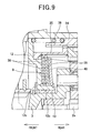
- the shock absorber 8 is, as shown in FIG. 9 , composed of a plurality of (e.g., 2 in the present embodiment) rotatable friction plates 38, a plurality of (e.g., 2 in the present embodiment) fixed friction plates 39 that are interleaved with the rotatable friction plates 38, and a Belleville spring 40 that presses the rotatable and fixed friction plates 38 and 39 forward to hold them between itself and the frame 12.
- the shock absorber 8 is disposed within a space between the outer periphery of the bearing box 12a formed in the frame 12 and the inner periphery of the movement restricting member 35.
- Each of the rotatable friction plates 38 has, as shown in FIG. 10 , an annular shape with a circular opening 38a formed at the radial center. Further, on the outer periphery of each of the rotatable friction plates 38, there are formed a plurality of protrusions 38b that protrude radially outward.
- Each of the fixed friction plates 39 has, as shown in FIGS. 11A and 11B , an annular shape with a circular opening 39a formed at the radial center. Further, on the inner periphery of each of the fixed friction plates 39, there are formed a plurality of protrusions 39b that are spaced in the circumferential direction of the fixed friction plate 39 to form a plurality of grooves 39c therebetween. Each of the protrusions 39b extends in the axial direction of the fixed friction plate 39 on one side of the fixed friction plate 39. Each of the protrusions 39b has a large-width portion 39b1 on the proximal side and a small-width portion 39b2 on the distal side.
- the large-width portion 39b1 has a larger width in the circumferential direction of the fixed friction plate 39 than the small-width portion 39b2. Further, the length of the large-width portion 39b1 in the axial direction of the fixed friction plate 39 is almost equal to the thickness of the rotatable friction plates 39.
- the circular opening 39a has a diameter almost equal to the outer diameter of the cylindrical bearing box 12a formed in the frame 12, permitting the fixed friction plate 39 to be fitted onto the bearing box 12a. Further, the sum of the diameter of the circular opening 39a and twice the thickness of the protrusions 39b is almost equal to the diameter of the circular opening 38a of each of the rotatable friction plates 38, allowing the protrusions 39b being fitted into the circular opening 38a.
- the grooves 39c have a width in the circumferential direction of the fixed friction plate 39 almost equal to that of the small-width portions 39b2 of the protrusions 39b. Consequently, the small-width portions 39b2 of the protrusions 39b in one fixed friction plate 39 can be fitted into the grooves 39c in another fixed friction plate 39.
- the rotatable friction plates 38 are alternately arranged with the fixed friction plates 39 on the outer periphery of the bearing box 12a formed in the frame 12. Further, the rotatable and fixed friction plates 38 and 39 are held between the frame 12 and the Belleville spring 40 under the restoring force of the Belleville spring 40.
- Each of the rotatable friction plates 38 is rotatable relative to the frame 12. Further, the protrusions 38b formed on the outer periphery of each of the rotatable friction plates 38 are respectively fitted into the grooves 35c (see FIG. 7 ) formed in the inner periphery of the movement restricting member' 35, thereby restricting relative rotation between the rotatable friction plate 38 and the movement restricting member 35.
- the most forward-located fixed friction plate 39 is restricted in rotation by fitting the small-width portions 39b2 of the protrusions 39b formed therein respectively into grooves 12c (see FIG. 9 ) formed in the frame 12.
- the other fixed friction plate 39 is restricted in rotation by fitting the small-width portions 39b2 of the protrusions 39b formed therein into the grooves 39c formed in the most forward-located fixed friction plate 39.
- the Belleville spring 40 is crimped on the outer periphery of the cylindrical bearing box 12a, with the slip torque of the rotatable friction plates 38 set to a predetermined value.
- the solenoid of the solenoid switch 7 When the solenoid of the solenoid switch 7 is energized upon closing the starter switch, it creates a magnetic attraction to attract the plunger 15 to move forward. Then, with the forward movement of the plunger 15, the pinion gear 5 is shifted forward, together with the clutch 4, by the shift lever 6 to mesh with the ring gear of the engine. At the same time, with the forward movement of the plunger 15, the main contacts of the power supply circuit of the motor 2 are closed, so that the motor 2 is supplied with electric power from the battery to generate torque. Further, the rotation of the armature 2a of the motor 2 is transmitted, through the speed reduction by the speed reducer assembly at either of the first and second speed reduction ratios, to the pinion gear 5 via the output shaft 3 and the clutch 4. Consequently, the torque generated by the motor 2 is transmitted from the pinion gear 5 to the ring gear of the engine, thereby starting the engine.
- the solenoid of the solenoid switch 7 is deenergized upon opening the starter switch, causing the magnetic attraction for the plunger 15 to disappear. Then, the plunger 15 is returned forward by the return spring to its initial position, thereby opening the main contacts of the power supply circuit of the motor 2. At the same time, with the returning movement of the plunger 15, the pinion gear 5 is shifted backward, together with the clutch 4, by the shift lever 6 to its initial position. Consequently, the pinion gear 5 is detached from the ring gear of the engine, so that torque transmission between the motor 2 and the engine is interrupted.
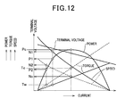
- FIG. 12 shows the performance characteristics of the starter 1, where both the output toque and output speed of the starter 1 when the first speed reducer is used are indicated with solid lines and those when the second speed reducer is used are indicated with dashed lines.
- the torque required to start the engine is equal to, for' example, Tc.
- the speed reduction assembly reduces the speed of the motor 2 at the second speed reduction ratio (i.e., the second speed reducer is selected), and the output power and output speed of the starter 1 are respectively equal to Pc and Nc.
- the second speed reduction ratio which is higher than the first speed reduction ratio, is so set as to be equal to the fixed speed reduction ratio of a conventional starter that includes only a single speed reducer.
- the starter 1 can reliably output the torque Tc required to start the engine at the low ambient temperature of below -20°C.
- the torque required to start the engine is decreased from Tc to, for example, Tw.
- the speed reduction assembly reduces the speed of the motor 2 at the first speed reduction ratio (i.e., the first speed reducer is selected), and the output power and output speed of the starter 1 are respectively equal to P1 and N 1.
- the starter 1 according to the present embodiment can output higher power and speed at normal operating temperatures, thereby considerably shortening the time required to start the engine.
- the gear engaging member 34 is mechanically connected to the rotatable friction plates 38 of the shock absorber 8 via the movement restricting member 35. More specifically, the outer teeth 35b of the movement restricting member 35 are in mesh with the second inner teeth 34c of the gear engaging member 34, restricting relative rotation between the movement restricting member 35 and the gear engaging member 34. Further, the protrusions 38b formed on the outer peripheries of the rotatable friction plates 38 are fit in the grooves 35c formed in the inner periphery of the movement restricting member 35, restricting relative rotation between the rotatable friction plates 38 and the movement restricting member 35.
- the impulsive torque transmitted to the gear engaging member 34 is further transmitted to the rotatable friction plates 39 via the movement restricting member 35, and is consumed by friction between the rotatable friction plates 38 and both the fixed friction plates 39 and the frame 12.
- the shock input from the engine to the starter 1 is absorbed by the shock absorber 8.
- the above-described starter 1 according to the present embodiment has the following advantages.
- the speed reducer assembly includes the first and second planetary speed reducers that respectively have the first and second speed reduction ratios; the first speed reduction ratio is lower than the second speed reduction ratio.
- the speed reduction ratio shifter shifts the speed reduction ratio of the speed reducer assembly between the first and second speed reduction ratios according to the ambient temperature.
- the speed reduction ratio shifter shifts the speed reduction ratio of the speed reducer assembly to the first speed reduction ratio. Consequently, the output speed of the starter 1 can be increased, thereby shortening the time required to start the engine.
- the speed reduction ratio shifter shifts the speed reduction ratio of the speed reducer assembly to the second speed reduction ratio. Consequently, the starter 1 can reliably output the torque required to start the engine though the engine friction is large at such a low ambient temperature.
- the speed reduction ratio shifter includes the gear engaging member 34 and the driver for driving the gear engaging member.
- the gear engaging member 34 is movable in the axial direction of the armature shaft 2b and selectively engages with one of the first and second internal gears 25 and 29, thereby restricting rotation of the engaged one of the first and second internal gears 25 and 29 while allowing rotation of the other.
- the driver includes the first spring 36 made of the shape memory alloy and the second spring 37 made of the ordinary spring material. The driver drives the gear engaging member 34 to move in the axial direction of the armature shaft 2b by using the difference between the restoring forces of the first and second springs 36 and 37; the difference depends on the ambient temperature.
- the gear engaging member 34 is moved in the axial direction of the armature shaft 2b only by using the difference between the restoring forces of the first and second springs 36 and 37. Consequently, no electric power is needed to drive the gear engaging member 34, saving the total electric power consumption for the engine start operation.
- the gear engaging member 34 is moved only in the axial direction of the armature shaft 2b. Consequently, without having to move the gear engaging member 34 in the radial direction of the armature shaft 2b, the radial dimension of the starter 1 can be minimized.
- the first internal gear 25 has the outer teeth 25c that is formed on the outer periphery of the first internal gear 25 on the front side.
- the second internal gear 29 has the outer teeth 29d that is formed on the outer periphery of the second internal gear 29 on the rear side.
- the gear engaging member 34 has formed, on the inner periphery thereof, the first inner teeth 34b for engaging with the outer teeth 25c of the first internal gear 25 as well as with the outer teeth 29d of the second internal gear 29.
- the axial distance between the outer teeth 25c of the first internal gear 25 and the outer teeth 29d of the second internal gear 29 can be minimized, thereby making it possible to minimize the axial length of the gear engaging member 34.
- the engaging portions of the gear engaging member 34 for engaging with the first and second internal gears 25 and 29 are integrally formed into the common first internal teeth 34b, the number of components of the starter 1 can be reduced, thereby reducing the manufacturing cost of the starter 1.
- the first internal gear 25 has a protrusion 25a (i.e., the annular small-outer diameter portion 25a as shown in FIG. 4 ) formed on the front side
- the second internal gear 29 has the recess 29a formed on the rear side.
- the first and second internal gears 25 and 29 are so disposed as to be rotatable relative to each other with the protrusion 25a fit in the recess 29a.
- the axes of the first and second internal gears 25 and 29 can be made coincident with each other, allowing the gear engaging member (34) to be smoothly moved between the first and second engagement positions.
- the speed reduction ratio of the speed reducer assembly can be smoothly shifted between the first and second speed reduction ratios.
- the gear engaging member 34 has the second inner teeth 34c formed on the inner periphery
- the movement restricting member 35 has the outer teeth 35b formed on the outer periphery.
- the second inner teeth 34c of the gear engaging member 34 mesh with the outer teeth 35b of the movement restricting member 35.
- shock absorber 8 to absorb shocks input from the engine to the starter 1.
- the shock absorber 8 it is possible to protect the starter 1 from the shocks. Further, with the use of the shock absorber 8, the modules of the first and second internal gears 25 and 29 can be reduced, thereby downsizing the first and second internal gears 25 and 29.
- the shock absorber 8 is disposed within the space between the outer periphery of the bearing box 12a formed in the frame 12 and the inner periphery of the movement restricting member 35.
- the rotatable friction plates 38 are alternately arranged in the axial direction of the armature shaft 2b with the fixed friction plates 39.
- the above arrangement allows the shock absorber 8 to be easily disposed within the above-described space. Further, the arrangement allows the use of sufficient number of the rotatable and fixed friction plates 38 and 39, thereby ensuring the shock-absorbing capability of the shock absorber 8.
- most engaging portions between the first and second internal gears 25 and 29, the gear engaging member 34, and the movement restricting member 35 are embodied in the form of teeth, such as the outer teeth 25a of the first internal gear 25, the outer teeth 29a of the second internal gear 29, the first and second inner teeth 34b and 34c of the gear engaging member 34, and the outer teeth 35b of the movement restricting member 35.
- those engaging portions may also be embodied in other concave-convex forms, such as a combination of a plurality of protrusions with a plurality of recesses.
Landscapes
- Engineering & Computer Science (AREA)
- Chemical & Material Sciences (AREA)
- Combustion & Propulsion (AREA)
- Mechanical Engineering (AREA)
- General Engineering & Computer Science (AREA)
- Connection Of Motors, Electrical Generators, Mechanical Devices, And The Like (AREA)
- Structure Of Transmissions (AREA)
- Retarders (AREA)
Applications Claiming Priority (1)
| Application Number | Priority Date | Filing Date | Title |
|---|---|---|---|
| JP2007314786A JP4957530B2 (ja) | 2007-12-05 | 2007-12-05 | スタータ |
Publications (3)
| Publication Number | Publication Date |
|---|---|
| EP2067984A2 true EP2067984A2 (de) | 2009-06-10 |
| EP2067984A3 EP2067984A3 (de) | 2010-05-19 |
| EP2067984B1 EP2067984B1 (de) | 2012-05-30 |
Family
ID=40427667
Family Applications (1)
| Application Number | Title | Priority Date | Filing Date |
|---|---|---|---|
| EP20080020899 Expired - Fee Related EP2067984B1 (de) | 2007-12-05 | 2008-12-02 | Anlasser mit zwei Planetengetriebedrehzahlminderern mit unterschiedlichen Drehzahlminderungsverhältnissen |
Country Status (2)
| Country | Link |
|---|---|
| EP (1) | EP2067984B1 (de) |
| JP (1) | JP4957530B2 (de) |
Cited By (7)
| Publication number | Priority date | Publication date | Assignee | Title |
|---|---|---|---|---|
| FR2969219A1 (fr) * | 2010-12-20 | 2012-06-22 | Valeo Equip Electr Moteur | Ensemble pour reducteur de vitesse d'une machine electrique tournante et demarreur pour moteur thermique associe |
| EP2698269A3 (de) * | 2012-08-14 | 2014-03-12 | ZF Friedrichshafen AG | Antriebssystem für ein Fahrzeug |
| DE102013209022A1 (de) * | 2013-05-15 | 2014-11-20 | Schaeffler Technologies Gmbh & Co. Kg | Starteranordnung für einen Verbrennungsmotor und Verfahren zum Betreiben der Starteranordnung. |
| CN109884764A (zh) * | 2017-12-06 | 2019-06-14 | 深圳光峰科技股份有限公司 | 镜头模组及投影设备 |
| EP3604791A1 (de) | 2018-08-03 | 2020-02-05 | Mahle International GmbH | Anlasseinrichtung für eine brennkraftmaschine |
| CN113309840A (zh) * | 2021-06-23 | 2021-08-27 | 重庆理工大学 | 一种采煤机截割部自适应调速传动装置 |
| CN113531059A (zh) * | 2020-04-10 | 2021-10-22 | 赛峰传动系统公司 | 飞行器涡轮机的机械减速装置 |
Families Citing this family (2)
| Publication number | Priority date | Publication date | Assignee | Title |
|---|---|---|---|---|
| JP6369135B2 (ja) * | 2014-03-26 | 2018-08-08 | 株式会社デンソー | スタータ |
| JP6364974B2 (ja) * | 2014-06-04 | 2018-08-01 | 株式会社デンソー | エンジン始動装置 |
Citations (3)
| Publication number | Priority date | Publication date | Assignee | Title |
|---|---|---|---|---|
| JPS6128756A (ja) | 1984-07-18 | 1986-02-08 | Nippon Denso Co Ltd | 遊星歯車減速機構付スタ−タ |
| JPS61236951A (ja) | 1985-04-11 | 1986-10-22 | Kito Corp | 遊星歯車式2段変速装置を有する電動チェーンブロック |
| JPS61282650A (ja) | 1985-06-10 | 1986-12-12 | Takashi Takahashi | 遊星歯車機構 |
Family Cites Families (6)
| Publication number | Priority date | Publication date | Assignee | Title |
|---|---|---|---|---|
| JPS54153936A (en) * | 1978-05-26 | 1979-12-04 | Hitachi Ltd | Starter |
| EP0582429A1 (de) * | 1992-08-06 | 1994-02-09 | Ford Motor Company | Verbundumlaufgetriebevorrichtung für Anlasser eines Verbrennungsmotors |
| US6409622B1 (en) * | 1998-11-14 | 2002-06-25 | Robert Bosch Gmbh | Electric motor with drive |
| JP4137372B2 (ja) * | 2000-12-28 | 2008-08-20 | 日本電産サンキョー株式会社 | ギアードモータ |
| JP2004218627A (ja) * | 2002-11-19 | 2004-08-05 | Denso Corp | 内燃機関用スタータ |
| JP2007303278A (ja) * | 2006-05-08 | 2007-11-22 | Mazda Motor Corp | エンジンの始動装置 |
-
2007
- 2007-12-05 JP JP2007314786A patent/JP4957530B2/ja active Active
-
2008
- 2008-12-02 EP EP20080020899 patent/EP2067984B1/de not_active Expired - Fee Related
Patent Citations (3)
| Publication number | Priority date | Publication date | Assignee | Title |
|---|---|---|---|---|
| JPS6128756A (ja) | 1984-07-18 | 1986-02-08 | Nippon Denso Co Ltd | 遊星歯車減速機構付スタ−タ |
| JPS61236951A (ja) | 1985-04-11 | 1986-10-22 | Kito Corp | 遊星歯車式2段変速装置を有する電動チェーンブロック |
| JPS61282650A (ja) | 1985-06-10 | 1986-12-12 | Takashi Takahashi | 遊星歯車機構 |
Cited By (15)
| Publication number | Priority date | Publication date | Assignee | Title |
|---|---|---|---|---|
| FR2969219A1 (fr) * | 2010-12-20 | 2012-06-22 | Valeo Equip Electr Moteur | Ensemble pour reducteur de vitesse d'une machine electrique tournante et demarreur pour moteur thermique associe |
| WO2012085424A1 (fr) * | 2010-12-20 | 2012-06-28 | Valeo Equipements Electriques Moteur | Ensemble pour reducteur de vitesse d'une machine electrique tournante et demarreur pour moteur thermique associe |
| CN103270290A (zh) * | 2010-12-20 | 2013-08-28 | 法雷奥电机设备公司 | 用于旋转电机的减速器的组件和相关的热机起动器 |
| CN103270290B (zh) * | 2010-12-20 | 2016-08-10 | 法雷奥电机设备公司 | 用于旋转电机的减速器的组件和相关的热机起动器 |
| US9309856B2 (en) | 2010-12-20 | 2016-04-12 | Valeo Equipements Electriques Moteur | Assembly for a speed reducer of a rotary electric machine, and related heat-engine starter |
| EP2698269A3 (de) * | 2012-08-14 | 2014-03-12 | ZF Friedrichshafen AG | Antriebssystem für ein Fahrzeug |
| DE102013209022B4 (de) * | 2013-05-15 | 2016-07-07 | Schaeffler Technologies AG & Co. KG | Starteranordnung für einen Verbrennungsmotor und Verfahren zum Betreiben der Starteranordnung. |
| DE102013209022A1 (de) * | 2013-05-15 | 2014-11-20 | Schaeffler Technologies Gmbh & Co. Kg | Starteranordnung für einen Verbrennungsmotor und Verfahren zum Betreiben der Starteranordnung. |
| CN109884764A (zh) * | 2017-12-06 | 2019-06-14 | 深圳光峰科技股份有限公司 | 镜头模组及投影设备 |
| EP3604791A1 (de) | 2018-08-03 | 2020-02-05 | Mahle International GmbH | Anlasseinrichtung für eine brennkraftmaschine |
| DE102018212995A1 (de) * | 2018-08-03 | 2020-02-06 | Mahle Lnternational Gmbh | Anlasseinrichtung für eine Brennkraftmaschine |
| DE102018212995B4 (de) * | 2018-08-03 | 2021-03-18 | Mahle Lnternational Gmbh | Anlasseinrichtung für eine Brennkraftmaschine |
| CN113531059A (zh) * | 2020-04-10 | 2021-10-22 | 赛峰传动系统公司 | 飞行器涡轮机的机械减速装置 |
| CN113309840A (zh) * | 2021-06-23 | 2021-08-27 | 重庆理工大学 | 一种采煤机截割部自适应调速传动装置 |
| CN113309840B (zh) * | 2021-06-23 | 2022-09-06 | 重庆理工大学 | 一种采煤机截割部自适应调速传动装置 |
Also Published As
| Publication number | Publication date |
|---|---|
| EP2067984A3 (de) | 2010-05-19 |
| JP2009142035A (ja) | 2009-06-25 |
| EP2067984B1 (de) | 2012-05-30 |
| JP4957530B2 (ja) | 2012-06-20 |
Similar Documents
| Publication | Publication Date | Title |
|---|---|---|
| EP2067984B1 (de) | Anlasser mit zwei Planetengetriebedrehzahlminderern mit unterschiedlichen Drehzahlminderungsverhältnissen | |
| EP2006533B1 (de) | Motoranlasser | |
| US7451668B2 (en) | Starter having excessive-torque-absorbing device | |
| EP2048356B1 (de) | Drehzahlreduktionsstarter für Motoren | |
| US8091443B2 (en) | Speed reduction type starter for engines | |
| JP4572912B2 (ja) | スタータ | |
| CN100529380C (zh) | 具有支撑拨叉支点部分的可靠支点支架的起动机 | |
| EP1970560B1 (de) | Motoranlasser mit verbesserter spiralförmiger Keilnutgestalt zur Gewährleistung der zuverlässigen Kupplung zwischen Abtriebswelle und Ritzel | |
| JP5115218B2 (ja) | スタータ | |
| JP4487976B2 (ja) | スタータ | |
| JP2004218627A (ja) | 内燃機関用スタータ | |
| JP3584719B2 (ja) | スタータ | |
| JP2009068389A (ja) | スタータ | |
| US7814807B2 (en) | Engine starter having intermediate gear | |
| US20090195098A1 (en) | Starter for cranking internal combustion engine | |
| US8567364B2 (en) | Starter equipped with planetary speed reducer and shock absorber | |
| JP2006125325A (ja) | スタータ | |
| CN104179615A (zh) | 电机以及用于制造和/或运行该电机的方法 | |
| JP4816596B2 (ja) | スタータ | |
| JP4174829B2 (ja) | スタータ | |
| JP4305422B2 (ja) | スタータおよびその製造方法 | |
| JP2006250046A (ja) | スタータ | |
| JP6047356B2 (ja) | スタータ | |
| JP2005325974A (ja) | 伝動装置の打音防止機構 | |
| JP2004108376A (ja) | スタータ |
Legal Events
| Date | Code | Title | Description |
|---|---|---|---|
| PUAI | Public reference made under article 153(3) epc to a published international application that has entered the european phase |
Free format text: ORIGINAL CODE: 0009012 |
|
| AK | Designated contracting states |
Kind code of ref document: A2 Designated state(s): AT BE BG CH CY CZ DE DK EE ES FI FR GB GR HR HU IE IS IT LI LT LU LV MC MT NL NO PL PT RO SE SI SK TR |
|
| AX | Request for extension of the european patent |
Extension state: AL BA MK RS |
|
| RIN1 | Information on inventor provided before grant (corrected) |
Inventor name: NIIMI, MASAMI |
|
| PUAL | Search report despatched |
Free format text: ORIGINAL CODE: 0009013 |
|
| AK | Designated contracting states |
Kind code of ref document: A3 Designated state(s): AT BE BG CH CY CZ DE DK EE ES FI FR GB GR HR HU IE IS IT LI LT LU LV MC MT NL NO PL PT RO SE SI SK TR |
|
| AX | Request for extension of the european patent |
Extension state: AL BA MK RS |
|
| 17P | Request for examination filed |
Effective date: 20100630 |
|
| AKX | Designation fees paid |
Designated state(s): DE FR |
|
| REG | Reference to a national code |
Ref country code: DE Ref legal event code: R079 Ref document number: 602008015974 Country of ref document: DE Free format text: PREVIOUS MAIN CLASS: F02N0015060000 Ipc: F02N0015040000 |
|
| GRAP | Despatch of communication of intention to grant a patent |
Free format text: ORIGINAL CODE: EPIDOSNIGR1 |
|
| RIC1 | Information provided on ipc code assigned before grant |
Ipc: F02N 15/04 20060101AFI20111018BHEP |
|
| GRAS | Grant fee paid |
Free format text: ORIGINAL CODE: EPIDOSNIGR3 |
|
| GRAA | (expected) grant |
Free format text: ORIGINAL CODE: 0009210 |
|
| GRAL | Information related to payment of fee for publishing/printing deleted |
Free format text: ORIGINAL CODE: EPIDOSDIGR3 |
|
| GRAS | Grant fee paid |
Free format text: ORIGINAL CODE: EPIDOSNIGR3 |
|
| AK | Designated contracting states |
Kind code of ref document: B1 Designated state(s): DE FR |
|
| REG | Reference to a national code |
Ref country code: DE Ref legal event code: R096 Ref document number: 602008015974 Country of ref document: DE Effective date: 20120726 |
|
| PLBE | No opposition filed within time limit |
Free format text: ORIGINAL CODE: 0009261 |
|
| STAA | Information on the status of an ep patent application or granted ep patent |
Free format text: STATUS: NO OPPOSITION FILED WITHIN TIME LIMIT |
|
| 26N | No opposition filed |
Effective date: 20130301 |
|
| REG | Reference to a national code |
Ref country code: DE Ref legal event code: R097 Ref document number: 602008015974 Country of ref document: DE Effective date: 20130301 |
|
| PGFP | Annual fee paid to national office [announced via postgrant information from national office to epo] |
Ref country code: FR Payment date: 20131220 Year of fee payment: 6 |
|
| REG | Reference to a national code |
Ref country code: FR Ref legal event code: ST Effective date: 20150831 |
|
| PG25 | Lapsed in a contracting state [announced via postgrant information from national office to epo] |
Ref country code: FR Free format text: LAPSE BECAUSE OF NON-PAYMENT OF DUE FEES Effective date: 20141231 |
|
| PGFP | Annual fee paid to national office [announced via postgrant information from national office to epo] |
Ref country code: DE Payment date: 20191210 Year of fee payment: 12 |
|
| REG | Reference to a national code |
Ref country code: DE Ref legal event code: R119 Ref document number: 602008015974 Country of ref document: DE |
|
| PG25 | Lapsed in a contracting state [announced via postgrant information from national office to epo] |
Ref country code: DE Free format text: LAPSE BECAUSE OF NON-PAYMENT OF DUE FEES Effective date: 20210701 |