EP2068012A2 - Vis à taraudage parciellement durci - Google Patents
Vis à taraudage parciellement durci Download PDFInfo
- Publication number
- EP2068012A2 EP2068012A2 EP08105905A EP08105905A EP2068012A2 EP 2068012 A2 EP2068012 A2 EP 2068012A2 EP 08105905 A EP08105905 A EP 08105905A EP 08105905 A EP08105905 A EP 08105905A EP 2068012 A2 EP2068012 A2 EP 2068012A2
- Authority
- EP
- European Patent Office
- Prior art keywords
- screw
- fastening component
- component
- marked
- thread
- Prior art date
- Legal status (The legal status is an assumption and is not a legal conclusion. Google has not performed a legal analysis and makes no representation as to the accuracy of the status listed.)
- Withdrawn
Links
Images


Classifications
-
- F—MECHANICAL ENGINEERING; LIGHTING; HEATING; WEAPONS; BLASTING
- F16—ENGINEERING ELEMENTS AND UNITS; GENERAL MEASURES FOR PRODUCING AND MAINTAINING EFFECTIVE FUNCTIONING OF MACHINES OR INSTALLATIONS; THERMAL INSULATION IN GENERAL
- F16B—DEVICES FOR FASTENING OR SECURING CONSTRUCTIONAL ELEMENTS OR MACHINE PARTS TOGETHER, e.g. NAILS, BOLTS, CIRCLIPS, CLAMPS, CLIPS OR WEDGES; JOINTS OR JOINTING
- F16B33/00—Features common to bolt and nut
- F16B33/06—Surface treatment of parts furnished with screw-thread, e.g. for preventing seizure or fretting
-
- F—MECHANICAL ENGINEERING; LIGHTING; HEATING; WEAPONS; BLASTING
- F16—ENGINEERING ELEMENTS AND UNITS; GENERAL MEASURES FOR PRODUCING AND MAINTAINING EFFECTIVE FUNCTIONING OF MACHINES OR INSTALLATIONS; THERMAL INSULATION IN GENERAL
- F16B—DEVICES FOR FASTENING OR SECURING CONSTRUCTIONAL ELEMENTS OR MACHINE PARTS TOGETHER, e.g. NAILS, BOLTS, CIRCLIPS, CLAMPS, CLIPS OR WEDGES; JOINTS OR JOINTING
- F16B5/00—Joining sheets or plates, e.g. panels, to one another or to strips or bars parallel to them
- F16B5/02—Joining sheets or plates, e.g. panels, to one another or to strips or bars parallel to them by means of fastening members using screw-thread
-
- F—MECHANICAL ENGINEERING; LIGHTING; HEATING; WEAPONS; BLASTING
- F16—ENGINEERING ELEMENTS AND UNITS; GENERAL MEASURES FOR PRODUCING AND MAINTAINING EFFECTIVE FUNCTIONING OF MACHINES OR INSTALLATIONS; THERMAL INSULATION IN GENERAL
- F16B—DEVICES FOR FASTENING OR SECURING CONSTRUCTIONAL ELEMENTS OR MACHINE PARTS TOGETHER, e.g. NAILS, BOLTS, CIRCLIPS, CLAMPS, CLIPS OR WEDGES; JOINTS OR JOINTING
- F16B35/00—Screw-bolts; Stay-bolts; Screw-threaded studs; Screws; Set screws
- F16B35/04—Screw-bolts; Stay-bolts; Screw-threaded studs; Screws; Set screws with specially-shaped head or shaft in order to fix the bolt on or in an object
- F16B35/06—Specially-shaped heads
- F16B35/065—Specially-shaped heads with self-countersink-cutting means
Definitions
- the invention relates to a device according to the preamble of claim 1.
- the object of the invention is in particular to provide a generic device with improved properties in terms of a stable attachment.
- the invention is based on a device, in particular a domestic appliance device, with at least one screw.
- the screw has at least one hardened threaded part.
- a "hardened threaded part" of a screw is to be understood as meaning, in particular, a part of a thread of the screw subjected to a hardening process, which after completion of the process has a greater hardness than immediately before the beginning of the process.
- a particularly stable attachment can be achieved.
- the threaded part is in particular a part of an M4 thread.
- the screw is not rusting. As a result, a high resistance can be achieved.
- the screw is at least partially formed of a stainless steel, whereby a cost-effective design can be achieved.
- the threaded part kolsterintestine is advantageously achieved with a constant shape of the screw.
- a high temperature resistance can be advantageously achieved in particular in a pyrolysis operation of a cooking appliance.
- the screw is thread-forming.
- a good electrically conductive connection between the screw and an internal thread can be achieved in a simple manner.
- a wear-free screw connection can be produced by means of the screw.
- the screw is in particular intended to furrow a thread in a sheet metal layer and / or in at least one enamel layer.
- the screw has at least one cylindrical threaded portion. In this way, a particularly good electrically conductive connection between the screw and an internal thread can be achieved in a simple manner.
- the screw has at least one threaded area, which tapers in a screwing-in direction.
- “the threaded portion” tapers in a screwing-in direction when there is an envelope limiting the threaded portion in a side view, which tapers in the screwing-in direction.
- a screwing-in direction of the screw is a direction extending from a head of the screw to a tip of the screw or a rounded tip of the screw, which is applied to the component in particular when the screw is screwed into a component.
- a threaded area is in particular the entire thread of the screw.
- the screw has a head with at least one toothing. In this way, a particularly stable attachment can be achieved.
- the screw has an opening angle of about 24 °.
- An "opening angle" of a screw is in particular an opening angle of a cone, which is a part of the screw and is arranged on an opposite end of the screw head of the screw and in particular has a rounded tip. Including that one Angle "about 24 °", it should be understood in particular that the angle deviates by less than twenty degrees, in particular by less than eight degrees and most advantageously by less than three degrees by 24 °. This allows a simple screwing the screw can be achieved.
- the device has at least one fastening component, which is intended to make a screw connection with the screw, and which has at least one enamel layer.
- a "fastening component” is, in particular, a component to which at least one further component is fastened in an assembled state, wherein the fastening is realized in particular by the screw connection.
- the device has at least one fastening component, which is intended to make a screw connection with the screw, and which is formed at least partially from a stainless steel.
- a wear-free screw connection between the fastening component and the screw which is in particular at least partially formed from a stainless steel and thread-forming, can be achieved.
- tearing or damage of threads, seizing and jamming upon repeated screwing in and out of the screw in the fastening component is avoided.
- the device has at least one fastening component which has a collar-shaped formation for coupling to the screw.
- This can advantageously be achieved a large contact area between the fastening component and the screw.
- the fastening component has at least one enamel layer, spalling of enamel can be advantageously prevented.
- the molding in particular extends in a longitudinal direction of the screw and / or forms an envelope of the screw.
- the "collar-shaped" shape of a fastening component is in particular a molding which has a surface which extends substantially perpendicular to a surface of the fastening component and which at least partially delimits a recess of the fastening component.
- a first surface extends "perpendicularly" to a second surface when the first surface has a first planar surface portion and the second surface comprises a second planar surface portion and the surface portions each lie in a plane so that the two planes subtend at least an angle which deviates by less than thirty degrees, more particularly by less than ten degrees, and most advantageously by less than three degrees by ninety degrees.
- the device has at least one fastening component and at least one component which is grounded due to attachment to the fastening component by means of the screw.
- the component is earthed according to VDE grounding standard 28.3.
- the component is preferably a heating functional element.
- a "heating functional element” is a temperature sensor, a distributor plate and / or a radiator.
- the fastening component is electrically conductively connected to the ground.
- the device has at least one fastening component, which is intended to enter into a screw connection with the screw, and which is a component of a cooking appliance muffle.
- a fastening component which is intended to enter into a screw connection with the screw, and which is a component of a cooking appliance muffle.
- the fastening component may be a Garretemuffelwand.
- a domestic appliance manufacturing method in which a screw formed at least partially from a stainless steel with a hardened threaded part is screwed into a recess of a fastening component which has an enamel layer.
- a thread-free collar is impressed, in which a thread is furrowed by the screw.
- a large contact area between the fastening component and the screw can be achieved. In particular, this spalling of email is prevented.
- FIG. 1 shows a designed as a cooking appliance home appliance 34 with a device 36.
- the device 36 has a component 26, which comprises a Schuvorgangsfunktionselement 37 and which is screwed by means of a thread-forming screw 10 to a fastening member 12.
- the fastening component 12 is part of a cooking appliance muffle 38 of the household appliance 34.
- the fastening component 12 forms a cooking appliance muffle wall which delimits a cooking chamber.
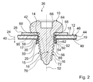
- FIG. 2 shows a II-II section through the device 36 along a main direction of extent 40 of the screw 10, through the screw 10, through the component 26 and through the fastening member 12 in an assembled state.
- the screw 10 is made of the A2 stainless steel with the material number 1.4567 and has a hardened by Kolster originated threaded portion 16 which receives a screw 14 with the fastening member 12.
- the component 26 is fastened to the fastening component 12 by means of the screw 10.
- the screw 14 holds a screw-in torque of three Newtonmeter without damage.
- a head 42 of the screw 10 is formed as a round head and is in the assembled state of the component 26 at. The screw 10 presses the component 26 against the fastening component 12 and passes through both the component 26 and the fastening component 12.
- a sheet 44 which is made of stainless steel, and two enamel layers 18, 19 are components of the fastening member 12.
- An upper surface 46 of the sheet 44 is covered by the enamel layer 18, a bottom 48 of the sheet 44 of the enamel layer 19.
- the sheet 44 has a thickness of eight hundred micrometers, the enamel layers 18, 19 each have a thickness of one hundred micrometers, and in principle a thinner version or a thicker design of one of the enamel layers 18, 19 of up to two hundred micrometers or more is conceivable.
- the component 26 abuts against the enamel layer 18.
- a part of the fastening component 12 is a collar-shaped formation 20, which surrounds a recess 30 of the fastening component 12, through which the screw 10 is screwed.
- a surface 50 of the molding 20 has a shape of a millimeter high cylinder jacket and extends parallel to a cylinder axis 52 of the cylinder jacket, which is directed perpendicular to the top and bottom 46, 48 of the sheet 44.
- the surface 50 directly adjoins the enamel layer 19 and is formed by a one hundred micron thick enamel layer 54.
- the molding 20 comprises an extension 56 of the sheet 44, which is shaping the shaping 20 and forms a right angle with the plate 44.
- the screw 10 is screwed.
- the internal thread 60 has surface portions 62 of the extension 56 made of sheet metal, which rest in the mounted state on the threaded portion 16 of the screw 10. Since the screw 10 also touches the component 26 and is conductive, by means of the screw 10 there is a conductive connection between the component 26 and the metal sheet 44. Because the fastening component 12 is earthed, the component 26 is grounded as well.
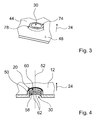
- a VDE-compliant grounding according to the grounding standard 28.3 is also because the length of the internal thread 60 is more than half as long as the diameter of the internal thread 60 ( FIG. 4 ).
- a screw-in direction 24 is parallel to the main extension direction 40 of the screw 10 and the cylinder axis 52 and extends from the head 42 to the fastening component 12 too.
- the threaded portion 16 has a toothing 82 with teeth 64, which in the sectional view of FIG. 2 have a shape of an imaginary triangle, wherein a side 66 of the triangle is disposed within the screw 10. This side 66 is opposite to a corner point 68, 69 of the triangle, which is arranged on a surface of the screw 10.
- a threaded portion 17 of the threaded portion 16, which bears against the internal thread 60, has a cylindrical shape.
- the device 36 is assembled in a home appliance manufacturing process, which will be described below.
- a collar-shaped formation 74 is embossed around the recess 30 of the sheet 44 ( FIG. 3 ), which is then coated together with the sheet 44 with an enamel layer of constant thickness.
- the formation 74 merges into the sheet 44 in a curved area 78 and forms a crater on the sheet 44.
- the screw 10 is screwed in from a side facing away from the crater of the sheet 44, wherein the screw 10, the internal thread 60 (FIG. Figures 2 and 4 ) in the molding 74 and the molding 74 thereby to the molding 20 as shown in FIG FIG. 2 reshapes. After screwing the screw 10, the device 36 is mounted.
- FIG. 4 shows a section through the collar-shaped formation 20 with the internal thread 60, wherein the representation of the enamel layers 18, 19 (see FIG. 2 ) was waived.
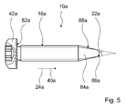
- FIG. 5 shows a side view of the alternative embodiment of a screw 10a with a section through a portion of a head 42a of the screw 10a.
- a threaded portion 16a of the screw 10a has been omitted for clarity.
- the screw 10 a On one side of the head 42 a, which abuts in a mounted state on the component 26, the screw 10 a has a toothing 82 a, which in an assembled state of the screw 10 a, in which the toothing 82 a is applied to the component 26, unscrewing the Screw 10a difficult.
- the screw 10a has a front portion 84 in the form of a cone 88 with a rounded tip 86, which is disposed at one end of the screw 10a, which is opposite to the head 42a.
- the cone 88 has an opening angle 22 of 24 °. In a main direction of extension of the screw 10a, this has a length of eight millimeters.
- FIG. 6 shows an alternative embodiment of a device 36b.
- the device 36b has a screw 10b with envelopes 90b, 92b in a threaded area 17b and envelopes 70b, 72b in a threaded area 15b.
- the envelopes 70b, 90b are parallel and immediately adjacent to each other. The same applies to the envelopes 72b, 92b.
- the envelopes 70b, 72b, 90b, 92b converge toward each other starting from a head 42b of the screw 10b.
- a threaded portion 16b is conical.
Landscapes
- Engineering & Computer Science (AREA)
- General Engineering & Computer Science (AREA)
- Mechanical Engineering (AREA)
- Cookers (AREA)
- Connection Of Plates (AREA)
- Mutual Connection Of Rods And Tubes (AREA)
- Non-Disconnectible Joints And Screw-Threaded Joints (AREA)
- Food-Manufacturing Devices (AREA)
Priority Applications (1)
| Application Number | Priority Date | Filing Date | Title |
|---|---|---|---|
| EP08105905A EP2068012A3 (fr) | 2007-12-03 | 2008-12-01 | Vis à taraudage parciellement durci |
Applications Claiming Priority (2)
| Application Number | Priority Date | Filing Date | Title |
|---|---|---|---|
| EP07360061 | 2007-12-03 | ||
| EP08105905A EP2068012A3 (fr) | 2007-12-03 | 2008-12-01 | Vis à taraudage parciellement durci |
Publications (2)
| Publication Number | Publication Date |
|---|---|
| EP2068012A2 true EP2068012A2 (fr) | 2009-06-10 |
| EP2068012A3 EP2068012A3 (fr) | 2011-11-23 |
Family
ID=40220164
Family Applications (1)
| Application Number | Title | Priority Date | Filing Date |
|---|---|---|---|
| EP08105905A Withdrawn EP2068012A3 (fr) | 2007-12-03 | 2008-12-01 | Vis à taraudage parciellement durci |
Country Status (1)
| Country | Link |
|---|---|
| EP (1) | EP2068012A3 (fr) |
Cited By (2)
| Publication number | Priority date | Publication date | Assignee | Title |
|---|---|---|---|---|
| EP2317161A1 (fr) * | 2009-10-29 | 2011-05-04 | Giga-Byte Technology Co., Ltd. | Enveloppe avec une feuille métallique et une vis d'étanchéité extrudés un trou taraudé dans la feuille métallique |
| CN110206806A (zh) * | 2019-05-29 | 2019-09-06 | 惠州Tcl移动通信有限公司 | 螺钉及螺纹固定结构 |
Family Cites Families (5)
| Publication number | Priority date | Publication date | Assignee | Title |
|---|---|---|---|---|
| GB717769A (en) * | 1952-01-11 | 1954-11-03 | George Thomas Mole | Improvements in or relating to guards for fires |
| US3045663A (en) * | 1959-09-28 | 1962-07-24 | Gen Motors Corp | Oven door mounting means |
| AU6661794A (en) * | 1993-05-04 | 1994-11-21 | Bergholtz, Goran | A screw |
| US7014386B1 (en) * | 1998-01-15 | 2006-03-21 | Wayne-Dalton Corp. | Screw connection of components to sheet material and method of effecting connection |
| JP4340103B2 (ja) * | 2002-09-12 | 2009-10-07 | 株式会社リコー | ねじ締結構造 |
-
2008
- 2008-12-01 EP EP08105905A patent/EP2068012A3/fr not_active Withdrawn
Cited By (2)
| Publication number | Priority date | Publication date | Assignee | Title |
|---|---|---|---|---|
| EP2317161A1 (fr) * | 2009-10-29 | 2011-05-04 | Giga-Byte Technology Co., Ltd. | Enveloppe avec une feuille métallique et une vis d'étanchéité extrudés un trou taraudé dans la feuille métallique |
| CN110206806A (zh) * | 2019-05-29 | 2019-09-06 | 惠州Tcl移动通信有限公司 | 螺钉及螺纹固定结构 |
Also Published As
| Publication number | Publication date |
|---|---|
| EP2068012A3 (fr) | 2011-11-23 |
Similar Documents
| Publication | Publication Date | Title |
|---|---|---|
| DE19533727C2 (de) | Spiral-flexibles Halteelement | |
| EP2049807B1 (fr) | Dispositif de fixation d'une pièce rapportée et d'une pièce de support à distance l'une de l'autre | |
| EP1568901B1 (fr) | Vis autotaraudeuse | |
| DE4002494C2 (fr) | ||
| EP3377777B1 (fr) | Vis de formage de filets ou de taraudage, en particulier pour utilisation dans du métal léger | |
| DE102014000940A1 (de) | Schraube, Befestigungsanordnung und Verwendung einer Schraube | |
| EP1718876A1 (fr) | Vis autotaraudeuse | |
| EP0905389A2 (fr) | Vis pour l'ancrage dans du béton | |
| EP3374649B1 (fr) | Vis autotaraudeuse | |
| DE3710096C2 (de) | Bolzen und Gegenstück | |
| DE19637969C2 (de) | Spanlos loch- und gewindeformende Dünnblechschraube | |
| DE102015223473A1 (de) | Buchse, Befestigungselement und Verfahren zum Anordnen eines Befestigungselements an einem Werkstück | |
| EP3034893B1 (fr) | Vis-cheville | |
| EP1426533A2 (fr) | Dispositif de fixation de ferrures sur des profilés à chambres | |
| EP2068012A2 (fr) | Vis à taraudage parciellement durci | |
| DE102008037202B4 (de) | Interferenzschraube | |
| DE102016101519A1 (de) | Schraube, Befestigungsanordnung, Verwendung einer Befestigungsanordnung und Verfahren zum Herstellen einer Schraube | |
| DE102014211093A1 (de) | Loch- und gewindeformende Schraube | |
| DE202012103721U1 (de) | Montageschraube zur Befestigung von Beschlagteilen, insbesondere von Bandteilen an Hohlkammerprofilen und einem Hohlkammerprofil | |
| WO2013123940A2 (fr) | Vis autotaraudeuse | |
| DE102010041165A1 (de) | Bohrschraube | |
| DE102022100106A1 (de) | Dämmstoffbefestiger | |
| EP1498618A2 (fr) | Vis pour matériaux durs | |
| WO2017102376A1 (fr) | Élément fileté | |
| DE102008057552A1 (de) | Kunststoff-Bauteil mit einem Einsteckloch für einen Haltezapfen mit Verankerungsrippen |
Legal Events
| Date | Code | Title | Description |
|---|---|---|---|
| PUAI | Public reference made under article 153(3) epc to a published international application that has entered the european phase |
Free format text: ORIGINAL CODE: 0009012 |
|
| AK | Designated contracting states |
Kind code of ref document: A2 Designated state(s): AT BE BG CH CY CZ DE DK EE ES FI FR GB GR HR HU IE IS IT LI LT LU LV MC MT NL NO PL PT RO SE SI SK TR |
|
| AX | Request for extension of the european patent |
Extension state: AL BA MK RS |
|
| PUAL | Search report despatched |
Free format text: ORIGINAL CODE: 0009013 |
|
| AK | Designated contracting states |
Kind code of ref document: A3 Designated state(s): AT BE BG CH CY CZ DE DK EE ES FI FR GB GR HR HU IE IS IT LI LT LU LV MC MT NL NO PL PT RO SE SI SK TR |
|
| AX | Request for extension of the european patent |
Extension state: AL BA MK RS |
|
| RIC1 | Information provided on ipc code assigned before grant |
Ipc: F16B 33/06 20060101AFI20111015BHEP |
|
| STAA | Information on the status of an ep patent application or granted ep patent |
Free format text: STATUS: THE APPLICATION HAS BEEN WITHDRAWN |
|
| 17P | Request for examination filed |
Effective date: 20120523 |
|
| 18W | Application withdrawn |
Effective date: 20120614 |