EP2068031A2 - Procédé destiné à la commande d'un véhicule automobile doté d'un embrayage automatisé - Google Patents
Procédé destiné à la commande d'un véhicule automobile doté d'un embrayage automatisé Download PDFInfo
- Publication number
- EP2068031A2 EP2068031A2 EP08167213A EP08167213A EP2068031A2 EP 2068031 A2 EP2068031 A2 EP 2068031A2 EP 08167213 A EP08167213 A EP 08167213A EP 08167213 A EP08167213 A EP 08167213A EP 2068031 A2 EP2068031 A2 EP 2068031A2
- Authority
- EP
- European Patent Office
- Prior art keywords
- driving
- accelerator pedal
- operating mode
- clutch
- actuating means
- Prior art date
- Legal status (The legal status is an assumption and is not a legal conclusion. Google has not performed a legal analysis and makes no representation as to the accuracy of the status listed.)
- Granted
Links
- 238000000034 method Methods 0.000 title claims abstract description 19
- 230000005540 biological transmission Effects 0.000 claims abstract description 20
- 230000007935 neutral effect Effects 0.000 claims description 11
- 230000003213 activating effect Effects 0.000 abstract 1
- 230000004913 activation Effects 0.000 description 4
- 230000001133 acceleration Effects 0.000 description 2
- 238000002485 combustion reaction Methods 0.000 description 2
- 230000001960 triggered effect Effects 0.000 description 2
- 238000004891 communication Methods 0.000 description 1
- 238000010276 construction Methods 0.000 description 1
- 230000009193 crawling Effects 0.000 description 1
- 230000001747 exhibiting effect Effects 0.000 description 1
- 238000002347 injection Methods 0.000 description 1
- 239000007924 injection Substances 0.000 description 1
- 238000012544 monitoring process Methods 0.000 description 1
Images

Classifications
-
- F—MECHANICAL ENGINEERING; LIGHTING; HEATING; WEAPONS; BLASTING
- F16—ENGINEERING ELEMENTS AND UNITS; GENERAL MEASURES FOR PRODUCING AND MAINTAINING EFFECTIVE FUNCTIONING OF MACHINES OR INSTALLATIONS; THERMAL INSULATION IN GENERAL
- F16D—COUPLINGS FOR TRANSMITTING ROTATION; CLUTCHES; BRAKES
- F16D48/00—External control of clutches
- F16D48/06—Control by electric or electronic means, e.g. of fluid pressure
-
- F—MECHANICAL ENGINEERING; LIGHTING; HEATING; WEAPONS; BLASTING
- F16—ENGINEERING ELEMENTS AND UNITS; GENERAL MEASURES FOR PRODUCING AND MAINTAINING EFFECTIVE FUNCTIONING OF MACHINES OR INSTALLATIONS; THERMAL INSULATION IN GENERAL
- F16D—COUPLINGS FOR TRANSMITTING ROTATION; CLUTCHES; BRAKES
- F16D2500/00—External control of clutches by electric or electronic means
- F16D2500/10—System to be controlled
- F16D2500/104—Clutch
- F16D2500/10406—Clutch position
- F16D2500/10412—Transmission line of a vehicle
-
- F—MECHANICAL ENGINEERING; LIGHTING; HEATING; WEAPONS; BLASTING
- F16—ENGINEERING ELEMENTS AND UNITS; GENERAL MEASURES FOR PRODUCING AND MAINTAINING EFFECTIVE FUNCTIONING OF MACHINES OR INSTALLATIONS; THERMAL INSULATION IN GENERAL
- F16D—COUPLINGS FOR TRANSMITTING ROTATION; CLUTCHES; BRAKES
- F16D2500/00—External control of clutches by electric or electronic means
- F16D2500/30—Signal inputs
- F16D2500/314—Signal inputs from the user
- F16D2500/31406—Signal inputs from the user input from pedals
- F16D2500/3144—Accelerator pedal position
-
- F—MECHANICAL ENGINEERING; LIGHTING; HEATING; WEAPONS; BLASTING
- F16—ENGINEERING ELEMENTS AND UNITS; GENERAL MEASURES FOR PRODUCING AND MAINTAINING EFFECTIVE FUNCTIONING OF MACHINES OR INSTALLATIONS; THERMAL INSULATION IN GENERAL
- F16D—COUPLINGS FOR TRANSMITTING ROTATION; CLUTCHES; BRAKES
- F16D2500/00—External control of clutches by electric or electronic means
- F16D2500/30—Signal inputs
- F16D2500/314—Signal inputs from the user
- F16D2500/31493—Switches on the dashboard
-
- F—MECHANICAL ENGINEERING; LIGHTING; HEATING; WEAPONS; BLASTING
- F16—ENGINEERING ELEMENTS AND UNITS; GENERAL MEASURES FOR PRODUCING AND MAINTAINING EFFECTIVE FUNCTIONING OF MACHINES OR INSTALLATIONS; THERMAL INSULATION IN GENERAL
- F16D—COUPLINGS FOR TRANSMITTING ROTATION; CLUTCHES; BRAKES
- F16D2500/00—External control of clutches by electric or electronic means
- F16D2500/50—Problem to be solved by the control system
- F16D2500/502—Relating the clutch
- F16D2500/50206—Creep control
- F16D2500/50209—Activation of the creep control operation
- F16D2500/50212—Accelerator pedal
-
- F—MECHANICAL ENGINEERING; LIGHTING; HEATING; WEAPONS; BLASTING
- F16—ENGINEERING ELEMENTS AND UNITS; GENERAL MEASURES FOR PRODUCING AND MAINTAINING EFFECTIVE FUNCTIONING OF MACHINES OR INSTALLATIONS; THERMAL INSULATION IN GENERAL
- F16D—COUPLINGS FOR TRANSMITTING ROTATION; CLUTCHES; BRAKES
- F16D2500/00—External control of clutches by electric or electronic means
- F16D2500/50—Problem to be solved by the control system
- F16D2500/502—Relating the clutch
- F16D2500/50206—Creep control
- F16D2500/50209—Activation of the creep control operation
- F16D2500/50221—Manual switch actuated by the user
-
- F—MECHANICAL ENGINEERING; LIGHTING; HEATING; WEAPONS; BLASTING
- F16—ENGINEERING ELEMENTS AND UNITS; GENERAL MEASURES FOR PRODUCING AND MAINTAINING EFFECTIVE FUNCTIONING OF MACHINES OR INSTALLATIONS; THERMAL INSULATION IN GENERAL
- F16D—COUPLINGS FOR TRANSMITTING ROTATION; CLUTCHES; BRAKES
- F16D2500/00—External control of clutches by electric or electronic means
- F16D2500/70—Details about the implementation of the control system
- F16D2500/704—Output parameters from the control unit; Target parameters to be controlled
- F16D2500/70402—Actuator parameters
- F16D2500/7041—Position
-
- F—MECHANICAL ENGINEERING; LIGHTING; HEATING; WEAPONS; BLASTING
- F16—ENGINEERING ELEMENTS AND UNITS; GENERAL MEASURES FOR PRODUCING AND MAINTAINING EFFECTIVE FUNCTIONING OF MACHINES OR INSTALLATIONS; THERMAL INSULATION IN GENERAL
- F16D—COUPLINGS FOR TRANSMITTING ROTATION; CLUTCHES; BRAKES
- F16D2500/00—External control of clutches by electric or electronic means
- F16D2500/70—Details about the implementation of the control system
- F16D2500/706—Strategy of control
- F16D2500/70663—State analysis; Analysing potential states of the machine and developing control strategies at each state
-
- F—MECHANICAL ENGINEERING; LIGHTING; HEATING; WEAPONS; BLASTING
- F16—ENGINEERING ELEMENTS AND UNITS; GENERAL MEASURES FOR PRODUCING AND MAINTAINING EFFECTIVE FUNCTIONING OF MACHINES OR INSTALLATIONS; THERMAL INSULATION IN GENERAL
- F16D—COUPLINGS FOR TRANSMITTING ROTATION; CLUTCHES; BRAKES
- F16D2500/00—External control of clutches by electric or electronic means
- F16D2500/70—Details about the implementation of the control system
- F16D2500/71—Actions
- F16D2500/7105—Inhibit control automatically
Definitions
- the commercial vehicle includes an automated manual transmission and an automated clutch and a switching device.
- the switching device for example a rotary switch
- the vehicle operating states forward drive “D", neutral “N” and reverse drive “R” and shunting circuits "RM, DM” or a maneuvering aid "RMB, DMB” can be selected.
- the maneuvering aid is activated, the clutch and the service friction brake are automatically actuated simultaneously and in coordination with each other, depending on the position of the accelerator pedal and the load state of the vehicle.
- the clutch and / or drive motor are actuated by a driving or accelerator pedal position specified by the vehicle driver.
- the driving or accelerator pedal deflection can be adjusted so that in the operating mode “maneuvering” or “creeping” a larger operating angle is permitted for a corresponding injection quantity than in the operating mode “driving ".
- the motor vehicle can thus be moved in the operating mode “maneuvering” or “creep” at the same adjustment angle of the driving or accelerator pedal at a lower speed.
- the present invention has for its object to represent a method for controlling a motor vehicle with automated clutch, by which the disadvantages of the prior art are minimized or eliminated and by which a safe operation of the automated clutch is enabled.
- the object underlying the invention is achieved by a, including the characterizing features of the main claim exhibiting, generic method for controlling a motor vehicle with automated clutch.
- the invention relates to a method for controlling a motor vehicle, in particular a commercial vehicle such as trucks, construction vehicles or buses, with an automatic transmission, ie an automatic or an automated transmission, with an automated clutch, a control device, a driving or accelerator pedal, an accelerator pedal position determining element and an actuating means for selecting an operating mode of the motor vehicle.
- the position of the driving or accelerator pedal is monitored or evaluated and that a control of the clutch is prevented until a change in the accelerator pedal position is detected.
- the clutch upon actuation of the actuating means from the operating mode “maneuvering” or “creeping” into the operating mode “driving", the clutch is only then closed further when detected by the element which detects the driving or accelerator pedal position , a change in the driving or accelerator pedal position is detected.
- a change in the driving or accelerator pedal position is detected.
- the clutch upon actuation of the actuating means from the operating mode “driving” to the operating mode “maneuvering” or “creeping", the clutch is not opened further until it is detected by the element which detects the driving or accelerator pedal position , a change in the driving or accelerator pedal position is detected.
- the drive train torque is changed by an activation of the clutch only when a change in the driving or accelerator pedal position is detected by the element which detects the driving or accelerator pedal position.
- the clutch when a gear is engaged from the neutral position, ie when the actuating means is actuated from the "neutral” mode to the “driving” or “maneuvering” or “creeping” mode, the clutch is only then activated and thus further closed when a change in the accelerator pedal position is detected by the member detecting the accelerator pedal position.
- the vehicle operator operates the accelerator pedal in the neutral position of the transmission and then changes to another mode by means of the actuating means, activation of the clutch is not carried out until the accelerator angle changes significantly, preferably in the direction of greater accelerator pedal angle.
- both the "forward drive range” and the “reverse drive range” are understood.
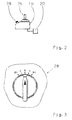
- the actuating means for selecting the operating mode of the motor vehicle may be designed, for example, as a rotary switch and are in communication with the control device of the motor vehicle.
- a rotary switch can be arranged for example on a drive switch of the motor vehicle, which is provided for the delivery of manual intervention of the driver and connected to the control device.
- the element for determining the driving or accelerator pedal position can be designed, for example, as a sensor arranged on the driving or accelerator pedal, with which the accelerator pedal position or the accelerator pedal angle of the driving or accelerator pedal is detected.
- the Fig. 1 shows a vehicle 2 with a prime mover 4, a transmission 6 and a clutch 8 arranged therebetween.
- the transmission 6 has a main transmission part 10, a split-group transmission 12 and a range group transmission 14.
- the prime mover 4 may be formed, for example, as an internal combustion engine.
- the transmission 6 is connected via connecting lines 18 to an electronic control device 20.
- a driving switch 16 is for the delivery of manual intervention of the driver provided and connected to the control device 20.
- the control device 20 is connected via a further connecting line with a sensor 30.
- the sensor 30 detects the position of a manually operated by a driver driving or accelerator pedal 32.
- the accelerator pedal position or the control device 20 is transmitted.
- the transmission 6 is automatically switched by an adjusting device 22 for signals that the adjusting device 22 receives from the control device 20.
- a clutch actuator 24 signals from the controller 20, whereby the clutch 8 is automatically actuated.
- the signal for the position of the driving or accelerator pedal 32 and the signal for the position of the actuating means 28 are transmitted here via corresponding connecting lines to the control device 20 and evaluated there.
Landscapes
- Engineering & Computer Science (AREA)
- General Engineering & Computer Science (AREA)
- Physics & Mathematics (AREA)
- Fluid Mechanics (AREA)
- Mechanical Engineering (AREA)
- Hydraulic Clutches, Magnetic Clutches, Fluid Clutches, And Fluid Joints (AREA)
- Control Of Driving Devices And Active Controlling Of Vehicle (AREA)
- Arrangement And Mounting Of Devices That Control Transmission Of Motive Force (AREA)
- Electric Propulsion And Braking For Vehicles (AREA)
Applications Claiming Priority (1)
| Application Number | Priority Date | Filing Date | Title |
|---|---|---|---|
| DE102007055722A DE102007055722A1 (de) | 2007-12-06 | 2007-12-06 | Verfahren zur Steuerung eines Kraftfahrzeugs mit automatisierter Kupplung |
Publications (3)
| Publication Number | Publication Date |
|---|---|
| EP2068031A2 true EP2068031A2 (fr) | 2009-06-10 |
| EP2068031A3 EP2068031A3 (fr) | 2012-10-17 |
| EP2068031B1 EP2068031B1 (fr) | 2014-03-12 |
Family
ID=40436352
Family Applications (1)
| Application Number | Title | Priority Date | Filing Date |
|---|---|---|---|
| EP08167213.1A Not-in-force EP2068031B1 (fr) | 2007-12-06 | 2008-10-22 | Procédé destiné à la commande d'un véhicule automobile doté d'un embrayage automatisé |
Country Status (3)
| Country | Link |
|---|---|
| US (1) | US8002668B2 (fr) |
| EP (1) | EP2068031B1 (fr) |
| DE (1) | DE102007055722A1 (fr) |
Families Citing this family (2)
| Publication number | Priority date | Publication date | Assignee | Title |
|---|---|---|---|---|
| JP5367682B2 (ja) * | 2010-12-16 | 2013-12-11 | アイシン・エーアイ株式会社 | 車両の動力伝達制御装置 |
| DE102017212992A1 (de) * | 2017-07-27 | 2019-01-31 | Continental Automotive Gmbh | System zur Auswahl von Fahrmanövern eines Fahrzeugs zum automatisierten Fahren |
Citations (2)
| Publication number | Priority date | Publication date | Assignee | Title |
|---|---|---|---|---|
| DE10016582A1 (de) | 2000-04-04 | 2001-10-11 | Zahnradfabrik Friedrichshafen | Rangiermodus bei Fahrzeugen mit automatisierter Kupplung |
| DE10105749A1 (de) | 2001-02-08 | 2002-08-14 | Man Nutzfahrzeuge Ag | Verfahren und Vorrichtung für ein erleichtertes Rangieren in einem Nutzfahrzeug |
Family Cites Families (6)
| Publication number | Priority date | Publication date | Assignee | Title |
|---|---|---|---|---|
| JP2631882B2 (ja) * | 1988-10-18 | 1997-07-16 | 富士重工業株式会社 | 車両用自動クラッチの制御装置 |
| JP3844596B2 (ja) * | 1998-06-15 | 2006-11-15 | 日産自動車株式会社 | ハイブリッド車両の制御装置 |
| JP2001208110A (ja) * | 2000-01-28 | 2001-08-03 | Mitsubishi Electric Corp | 歯車式自動変速装置及びその制御方法 |
| DE10219420A1 (de) * | 2002-05-02 | 2003-11-13 | Zf Sachs Ag | Kraftfahrzeug mit Kriechfunktion |
| JP4639743B2 (ja) * | 2003-12-12 | 2011-02-23 | 株式会社デンソー | クラッチ状態検出装置 |
| DE102004003946A1 (de) * | 2004-01-26 | 2005-08-18 | Voith Turbo Gmbh & Co. Kg | Verfahren zur Verhinderung einer unerwünschten Bewegung des Fahrzeuges entgegen der gewählten Fahrtrichtung, insbesondere an Steigungen |
-
2007
- 2007-12-06 DE DE102007055722A patent/DE102007055722A1/de not_active Withdrawn
-
2008
- 2008-10-22 EP EP08167213.1A patent/EP2068031B1/fr not_active Not-in-force
- 2008-12-04 US US12/328,148 patent/US8002668B2/en not_active Expired - Fee Related
Patent Citations (2)
| Publication number | Priority date | Publication date | Assignee | Title |
|---|---|---|---|---|
| DE10016582A1 (de) | 2000-04-04 | 2001-10-11 | Zahnradfabrik Friedrichshafen | Rangiermodus bei Fahrzeugen mit automatisierter Kupplung |
| DE10105749A1 (de) | 2001-02-08 | 2002-08-14 | Man Nutzfahrzeuge Ag | Verfahren und Vorrichtung für ein erleichtertes Rangieren in einem Nutzfahrzeug |
Also Published As
| Publication number | Publication date |
|---|---|
| US8002668B2 (en) | 2011-08-23 |
| EP2068031B1 (fr) | 2014-03-12 |
| DE102007055722A1 (de) | 2009-06-10 |
| US20090149297A1 (en) | 2009-06-11 |
| EP2068031A3 (fr) | 2012-10-17 |
Similar Documents
| Publication | Publication Date | Title |
|---|---|---|
| EP2483119B1 (fr) | Procédé de commande et/ou de régulation d'une boîte de vitesses automatisée | |
| DE19815260A1 (de) | Kraftfahrzeug | |
| EP1268231A1 (fr) | Mode de manoeuvre pour vehicules a embrayage automatise | |
| WO2019115668A1 (fr) | Système de commande d'entraînement pour un véhicule automobile pouvant fonctionner avec un moteur électrique, équipé d'un dispositif de sélection de rapports de vitesse | |
| EP3221615B1 (fr) | Procédé et dispositif pour faire fonctionner un véhicule automobile | |
| EP0928376B1 (fr) | Embrayage a commande automatique | |
| DE102008014495A1 (de) | Verfahren und Vorrichtung zur Steuerung eines Antriebsstrangs eines Fahrzeugs | |
| WO2021078476A1 (fr) | Unité de commande et procédé de changement de rapport manuel à l'aide d'une interface utilisateur graphique | |
| EP2068031B1 (fr) | Procédé destiné à la commande d'un véhicule automobile doté d'un embrayage automatisé | |
| EP1879768B1 (fr) | Procede pour activer un mode manoeuvre d'un vehicule automobile | |
| DE102013101244B4 (de) | Kupplungsbetätigungsvorrichtung für ein Kraftfahrzeug, Verfahren zur Kupplungsbetätigung für ein Kraftfahrzeug sowie Kraftfahrzeug | |
| DE102007023281B4 (de) | Vorrichtung zur elektronischen Steuerung einer Sperreinrichtung | |
| DE102017209414A1 (de) | Getriebevorrichtung für einen Kraftwagen und Verfahren zum Betreiben einer Getriebevorrichtung | |
| DE19802706B4 (de) | Elektronisch gesteuerter Fahrgeschwindigkeitsregler | |
| EP1057686A2 (fr) | Changement de vitesse pour véhicule à moteur | |
| DE102004057127A1 (de) | Verfahren und Steuerungsvorrichtung zum sicheren Trennen eines Antriebsstranges | |
| WO2007144297A1 (fr) | Procédé de commande d'un mode de manœuvre d'un véhicule automobile | |
| DE19823598B4 (de) | Verfahren und Vorrichtung zum Anzeigen der Neutralstellung eines im Antriebsstrang eines Kraftfahrzeugs enthaltenen Schaltgetriebes | |
| DE102013210223A1 (de) | Verfahren zur Ansteuerung eines manuellen Schaltgetriebes eines Kraftfahrzeugs | |
| DE19639289C1 (de) | Automatisch gesteuerte Kupplung | |
| DE10234083A1 (de) | Starteinrichtung für ein Kraftfahrzeug | |
| DE102006054020A1 (de) | Vorrichtung zur Betätigung einer Trennkupplung | |
| DE102012023969A1 (de) | Verfahren zur Steuerung eines Untersetzungsgetriebes eines Kraftfahrzeuges | |
| DE102014215236A1 (de) | Verfahren zur Steuerung des Antriebsstrangs eines Kraftfahrzeugs | |
| DE102008044033A1 (de) | Verfahren und Schaltanordnung zum Sperren und Freigeben von Schaltvorgängen |
Legal Events
| Date | Code | Title | Description |
|---|---|---|---|
| PUAI | Public reference made under article 153(3) epc to a published international application that has entered the european phase |
Free format text: ORIGINAL CODE: 0009012 |
|
| AK | Designated contracting states |
Kind code of ref document: A2 Designated state(s): AT BE BG CH CY CZ DE DK EE ES FI FR GB GR HR HU IE IS IT LI LT LU LV MC MT NL NO PL PT RO SE SI SK TR |
|
| AX | Request for extension of the european patent |
Extension state: AL BA MK RS |
|
| PUAL | Search report despatched |
Free format text: ORIGINAL CODE: 0009013 |
|
| AK | Designated contracting states |
Kind code of ref document: A3 Designated state(s): AT BE BG CH CY CZ DE DK EE ES FI FR GB GR HR HU IE IS IT LI LT LU LV MC MT NL NO PL PT RO SE SI SK TR |
|
| AX | Request for extension of the european patent |
Extension state: AL BA MK RS |
|
| RIC1 | Information provided on ipc code assigned before grant |
Ipc: F16D 48/06 20060101AFI20120907BHEP |
|
| 17P | Request for examination filed |
Effective date: 20130415 |
|
| 17Q | First examination report despatched |
Effective date: 20130522 |
|
| AKX | Designation fees paid |
Designated state(s): DE SE |
|
| GRAP | Despatch of communication of intention to grant a patent |
Free format text: ORIGINAL CODE: EPIDOSNIGR1 |
|
| INTG | Intention to grant announced |
Effective date: 20131029 |
|
| GRAS | Grant fee paid |
Free format text: ORIGINAL CODE: EPIDOSNIGR3 |
|
| GRAA | (expected) grant |
Free format text: ORIGINAL CODE: 0009210 |
|
| AK | Designated contracting states |
Kind code of ref document: B1 Designated state(s): DE SE |
|
| REG | Reference to a national code |
Ref country code: DE Ref legal event code: R096 Ref document number: 502008011443 Country of ref document: DE Effective date: 20140424 |
|
| REG | Reference to a national code |
Ref country code: SE Ref legal event code: TRGR |
|
| REG | Reference to a national code |
Ref country code: DE Ref legal event code: R097 Ref document number: 502008011443 Country of ref document: DE |
|
| PLBE | No opposition filed within time limit |
Free format text: ORIGINAL CODE: 0009261 |
|
| STAA | Information on the status of an ep patent application or granted ep patent |
Free format text: STATUS: NO OPPOSITION FILED WITHIN TIME LIMIT |
|
| 26N | No opposition filed |
Effective date: 20141215 |
|
| REG | Reference to a national code |
Ref country code: DE Ref legal event code: R097 Ref document number: 502008011443 Country of ref document: DE Effective date: 20141215 |
|
| REG | Reference to a national code |
Ref country code: SE Ref legal event code: EUG |
|
| PG25 | Lapsed in a contracting state [announced via postgrant information from national office to epo] |
Ref country code: SE Free format text: LAPSE BECAUSE OF NON-PAYMENT OF DUE FEES Effective date: 20141023 |
|
| PGFP | Annual fee paid to national office [announced via postgrant information from national office to epo] |
Ref country code: DE Payment date: 20151013 Year of fee payment: 8 |
|
| REG | Reference to a national code |
Ref country code: DE Ref legal event code: R119 Ref document number: 502008011443 Country of ref document: DE |
|
| PG25 | Lapsed in a contracting state [announced via postgrant information from national office to epo] |
Ref country code: DE Free format text: LAPSE BECAUSE OF NON-PAYMENT OF DUE FEES Effective date: 20170503 |