EP2068045A2 - Système d'entraînement d'un véhicule de travail - Google Patents
Système d'entraînement d'un véhicule de travail Download PDFInfo
- Publication number
- EP2068045A2 EP2068045A2 EP08169386A EP08169386A EP2068045A2 EP 2068045 A2 EP2068045 A2 EP 2068045A2 EP 08169386 A EP08169386 A EP 08169386A EP 08169386 A EP08169386 A EP 08169386A EP 2068045 A2 EP2068045 A2 EP 2068045A2
- Authority
- EP
- European Patent Office
- Prior art keywords
- actuator
- speed
- hydraulic pump
- drive system
- control device
- Prior art date
- Legal status (The legal status is an assumption and is not a legal conclusion. Google has not performed a legal analysis and makes no representation as to the accuracy of the status listed.)
- Granted
Links
Images
Classifications
-
- F—MECHANICAL ENGINEERING; LIGHTING; HEATING; WEAPONS; BLASTING
- F16—ENGINEERING ELEMENTS AND UNITS; GENERAL MEASURES FOR PRODUCING AND MAINTAINING EFFECTIVE FUNCTIONING OF MACHINES OR INSTALLATIONS; THERMAL INSULATION IN GENERAL
- F16H—GEARING
- F16H61/00—Control functions within control units of change-speed- or reversing-gearings for conveying rotary motion ; Control of exclusively fluid gearing, friction gearing, gearings with endless flexible members or other particular types of gearing
- F16H61/38—Control of exclusively fluid gearing
- F16H61/40—Control of exclusively fluid gearing hydrostatic
- F16H61/42—Control of exclusively fluid gearing hydrostatic involving adjustment of a pump or motor with adjustable output or capacity
- F16H61/431—Pump capacity control by electro-hydraulic control means, e.g. using solenoid valves
-
- B—PERFORMING OPERATIONS; TRANSPORTING
- B60—VEHICLES IN GENERAL
- B60W—CONJOINT CONTROL OF VEHICLE SUB-UNITS OF DIFFERENT TYPE OR DIFFERENT FUNCTION; CONTROL SYSTEMS SPECIALLY ADAPTED FOR HYBRID VEHICLES; ROAD VEHICLE DRIVE CONTROL SYSTEMS FOR PURPOSES NOT RELATED TO THE CONTROL OF A PARTICULAR SUB-UNIT
- B60W30/00—Purposes of road vehicle drive control systems not related to the control of a particular sub-unit, e.g. of systems using conjoint control of vehicle sub-units
- B60W30/18—Propelling the vehicle
- B60W30/188—Controlling power parameters of the driveline, e.g. determining the required power
- B60W30/1882—Controlling power parameters of the driveline, e.g. determining the required power characterised by the working point of the engine, e.g. by using engine output chart
-
- F—MECHANICAL ENGINEERING; LIGHTING; HEATING; WEAPONS; BLASTING
- F16—ENGINEERING ELEMENTS AND UNITS; GENERAL MEASURES FOR PRODUCING AND MAINTAINING EFFECTIVE FUNCTIONING OF MACHINES OR INSTALLATIONS; THERMAL INSULATION IN GENERAL
- F16H—GEARING
- F16H61/00—Control functions within control units of change-speed- or reversing-gearings for conveying rotary motion ; Control of exclusively fluid gearing, friction gearing, gearings with endless flexible members or other particular types of gearing
- F16H61/38—Control of exclusively fluid gearing
- F16H61/40—Control of exclusively fluid gearing hydrostatic
- F16H61/42—Control of exclusively fluid gearing hydrostatic involving adjustment of a pump or motor with adjustable output or capacity
- F16H61/421—Motor capacity control by electro-hydraulic control means, e.g. using solenoid valves
-
- F—MECHANICAL ENGINEERING; LIGHTING; HEATING; WEAPONS; BLASTING
- F16—ENGINEERING ELEMENTS AND UNITS; GENERAL MEASURES FOR PRODUCING AND MAINTAINING EFFECTIVE FUNCTIONING OF MACHINES OR INSTALLATIONS; THERMAL INSULATION IN GENERAL
- F16H—GEARING
- F16H61/00—Control functions within control units of change-speed- or reversing-gearings for conveying rotary motion ; Control of exclusively fluid gearing, friction gearing, gearings with endless flexible members or other particular types of gearing
- F16H61/38—Control of exclusively fluid gearing
- F16H61/40—Control of exclusively fluid gearing hydrostatic
- F16H61/46—Automatic regulation in accordance with output requirements
- F16H61/47—Automatic regulation in accordance with output requirements for achieving a target output speed
-
- B—PERFORMING OPERATIONS; TRANSPORTING
- B60—VEHICLES IN GENERAL
- B60W—CONJOINT CONTROL OF VEHICLE SUB-UNITS OF DIFFERENT TYPE OR DIFFERENT FUNCTION; CONTROL SYSTEMS SPECIALLY ADAPTED FOR HYBRID VEHICLES; ROAD VEHICLE DRIVE CONTROL SYSTEMS FOR PURPOSES NOT RELATED TO THE CONTROL OF A PARTICULAR SUB-UNIT
- B60W10/00—Conjoint control of vehicle sub-units of different type or different function
- B60W10/04—Conjoint control of vehicle sub-units of different type or different function including control of propulsion units
- B60W10/06—Conjoint control of vehicle sub-units of different type or different function including control of propulsion units including control of combustion engines
-
- B—PERFORMING OPERATIONS; TRANSPORTING
- B60—VEHICLES IN GENERAL
- B60W—CONJOINT CONTROL OF VEHICLE SUB-UNITS OF DIFFERENT TYPE OR DIFFERENT FUNCTION; CONTROL SYSTEMS SPECIALLY ADAPTED FOR HYBRID VEHICLES; ROAD VEHICLE DRIVE CONTROL SYSTEMS FOR PURPOSES NOT RELATED TO THE CONTROL OF A PARTICULAR SUB-UNIT
- B60W10/00—Conjoint control of vehicle sub-units of different type or different function
- B60W10/10—Conjoint control of vehicle sub-units of different type or different function including control of change-speed gearings
- B60W10/101—Infinitely variable gearings
- B60W10/103—Infinitely variable gearings of fluid type
-
- B—PERFORMING OPERATIONS; TRANSPORTING
- B60—VEHICLES IN GENERAL
- B60W—CONJOINT CONTROL OF VEHICLE SUB-UNITS OF DIFFERENT TYPE OR DIFFERENT FUNCTION; CONTROL SYSTEMS SPECIALLY ADAPTED FOR HYBRID VEHICLES; ROAD VEHICLE DRIVE CONTROL SYSTEMS FOR PURPOSES NOT RELATED TO THE CONTROL OF A PARTICULAR SUB-UNIT
- B60W2720/00—Output or target parameters relating to overall vehicle dynamics
- B60W2720/10—Longitudinal speed
-
- F—MECHANICAL ENGINEERING; LIGHTING; HEATING; WEAPONS; BLASTING
- F16—ENGINEERING ELEMENTS AND UNITS; GENERAL MEASURES FOR PRODUCING AND MAINTAINING EFFECTIVE FUNCTIONING OF MACHINES OR INSTALLATIONS; THERMAL INSULATION IN GENERAL
- F16H—GEARING
- F16H61/00—Control functions within control units of change-speed- or reversing-gearings for conveying rotary motion ; Control of exclusively fluid gearing, friction gearing, gearings with endless flexible members or other particular types of gearing
- F16H2061/0015—Transmission control for optimising fuel consumptions
Definitions
- Many work vehicles such as agricultural vehicles and harvesters, use hydraulic drives. They include a hydraulic pump driven by an internal combustion engine and a hydraulic motor connected to the hydraulic fluid-conducting hydraulic motor that drives one or more wheels.
- wheels of the front and rear axles are hydraulically driven by at least one hydraulic motor associated with the axles or the wheels.
- a drive system of the type mentioned is in the DE 102 11 799 A described.
- the swivel plate of the variable displacement hydraulic pump is controlled by an actuator and a control controlling it, depending on the position of an adjustable by the operator driving lever, so that one with the by the operator predetermined speed increasing hydraulic flow is generated.
- Two adjustable hydraulic motors are each assigned to the front or rear axle and also comprise adjustable pivot plates by actuators connected to the controller. The position of the swivel plates of the hydraulic motors is controlled on the basis of the output speed of the hydraulic motors and the pressure difference between their inlet and outlet, so that when spinning or against the desired direction backward rotating wheels can be counteracted accordingly.
- the DE 103 50 308 A describes a method of selecting engine speed and ratio in a continuously variable hydrostatic power split transmission comprising a hydrostatic transmission having a volume constant unit and a variable volume unit, and a summing gear and a range gear having a plurality of shiftable gears, the power input to the transmission being to the hydrostatic transmission and the range gear is branched and combined in the summing gear.
- the engine speed and the ratio of the power split transmission are automatically controlled so as to give optimum overall efficiency at a desired speed.
- the transmission described here includes only one variable hydraulic element (pump or motor), so that the adjustment of the engine speed must be used to meet the two conditions (achieving the desired speed and achieving the best possible efficiency).
- this arrangement is not suitable for self-propelled harvesters, the internal combustion engine is driven at least in the harvesting operation with a fixed, predetermined speed.
- a purely mechanical branch is still provided.
- the problem underlying the invention is seen to provide an improved drive system of a work vehicle, which does not have the disadvantages mentioned.
- the drive system of the work vehicle which may in particular be a self-propelled harvester, comprises an internal combustion engine.
- the internal combustion engine drives a hydraulic pump directly or indirectly, i. via interposed mechanical, hydraulic or any other gear.
- the hydraulic pump is connected via a hydraulic line to a hydraulic motor which mechanically drives a propulsion means in engagement with the ground, in particular a wheel or a tracked drive.
- the fluid displacements of the hydraulic pump and the hydraulic motor can be adjusted by a first actuator or a second actuator.
- a control device is connected to both actuators and a speed setting device, which provides a desired speed signal containing information about the desired desired speed with which the working vehicle is to be driven.
- the speed default device may be operated by the operator, or it may operate automatically to achieve, for example, a constant crop throughput.
- the control device has two degrees of freedom to achieve the desired speed, namely the positions of the actuators with which the fluid displacements of the hydraulic pump and the hydraulic motor are changed.
- One of the degrees of freedom is occupied by the desired set speed, while the present invention proposes to utilize the other degree of freedom so as to achieve an optimum (i.e., maximum) overall efficiency of the hydraulic transmission consisting of the hydraulic pump and the hydraulic motor.
- a further input parameter can be a detection of the torque delivered by the hydraulic motor by means of a torque sensor, which can be used to determine the speed of the internal combustion engine which is most suitable for providing the required torque or power.
- This variation of the rotational speed of the internal combustion engine is particularly useful in road driving operation, which is recognizable by means of a switch designed for switching between the field operation and the road driving operation.
- an operator or an automatic controller based on suitable sensor values, eg for the respective crop throughput
- suitable rotational speeds for the engine To provide operating units of the working machine, such as threshing and separating devices for combine harvesters or chaff and conveyors for forage harvesters.
- the efficiency of hydraulic pumps and hydraulic motors depends in particular on the pressure difference between the inlet and the outlet, which in turn is in connection with the predetermined by the respective actuator by adjusting the swash plate fluid displacement.
- the efficiency of the hydraulic transmission increases with increasing pressure to a specific value for the hydraulic pump or the hydraulic motor. It is therefore advisable to command the hydraulic pump and the hydraulic motor to these values so that they operate with the best efficiency by connecting the control device with a pressure sensor arranged to detect the pressure prevailing on the output side of the hydraulic pump and adjusting the actuators in such a way that that a pressure is achieved at the pressure sensor, wherein the overall efficiency of the Hydraulic pump and the hydraulic motor is maximum.
- This pressure can be stored in a memory device connected to the controller.
- the fluid displacement is reduced from a maximum fluid displacement until the optimum pressure is present.
- a fluid displacement causing greater than optimal pressure it will increase until the optimum pressure is reached.
- This optimum pressure may depend on the desired speed of the hydraulic motor, so that the speed of the hydraulic motor or the desired speed for selecting the pressure to be controlled can be used.
- suitable curves, formulas or tables can be stored and retrieved in a memory device of the control device.
- the swing angle of the hydraulic pump can be adjusted to the maximum possible value or an underlying value, but still sufficient to provide the required torque and offers better efficiency than the maximum tilt angle.
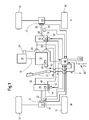
- FIG. 1 an embodiment of a drive system according to the invention is shown schematically.
- a work vehicle 8 has a frame (not shown) or a self-supporting chassis which rests on front propulsion means 10 and rear propulsion means 12 in the form of wheels which are in engagement with the ground.
- the rear propulsion means 12 are generally steerable, while the front propulsion means 10 are of larger diameter than the rear propulsion means 12 and support the greater part of the weight of the work vehicle 8, in particular when it is a harvester in the form of a combine harvester or self-propelled forage harvester.
- the drive system includes an internal combustion engine 14 in the form of a diesel engine. Via a shaft 16, the internal combustion engine 14 drives a hydraulic pump 18, the fluid displacement of which can be changed by a swashplate 20 whose position is controlled mechanically by a first actuator 62.
- the hydraulic pump 18 has an outlet connected by lines 24 to the inlet of a first hydraulic motor 26 and the inlet of a second hydraulic motor 28.
- An inlet of the hydraulic pump 18 is connected via lines 30 to the outlet of the first hydraulic motor 26 and the outlet of the second hydraulic motor 28. If the working vehicle 8 is a self-propelled harvesting machine, the internal combustion engine 14 also drives its crop processing devices.
- the first hydraulic motor 26 drives the two rear wheels 12 via a first drive shaft 32 and a first self-locking differential gear 34.
- the second hydraulic motor 28 drives the two front wheels 10 via a second drive shaft 36 and a second self-locking differential 38.
- the first hydraulic motor 26 may optionally be switched on and off, so that a four-wheel drive is selectable only in special operating situations in which a better traction is needed.
- a manual transmission with different, selectable gear ratios may be present, which in the FIG. 1 is not shown for reasons of clarity.
- a control device 40 is connected to a first rotational speed sensor 42, a second rotational speed sensor 44 and a first pressure sensor 46.
- the first speed sensor 42 is disposed adjacent to the first drive shaft 32 and outputs a pulse at each revolution (or several times during one revolution) of the first drive shaft 32. It may include an optical or magnetic sensor cooperating with corresponding markers or permanent magnets attached to the first drive shaft 32.
- the second speed sensor 44 is disposed adjacent to the second drive shaft 36 and emits a pulse at each revolution (or several times during one revolution) of the second drive shaft 36. It may include an optical or magnetic sensor cooperating with corresponding markers or permanent magnets attached to the second drive shaft 36.
- the pressure sensor 46 is disposed in the interior of the first hydraulic motor 26 and detects the pressure applied to the outlet of the first hydraulic motor 26.
- a drive lever position sensor 48 detects the position of a drive lever 22 attached to the operator workstation of the work vehicle 8. The drive lever position sensor 48 detects the current position of the drive lever 22 optically or magnetically.
- the control device 40 is connected to a second electromechanical actuator 52, which is set up for adjusting a swash plate 54 of the first hydraulic motor 26. Information about the position of the actuator 52 can be fed back to the control device 40. If a stepper motor is used as actuator 52, this feedback is unnecessary. It is also basically not necessary, since the operating state of the first hydraulic motor 26 is detected.
- the control device 40 receives from the second speed sensor 44, a measured value with respect to the rotational speed of the front wheels 10. In addition, the controller 40 receives from the first speed sensor 42 information about the rotational speed of the rear wheels 12th
- the second hydraulic motor 28 has a variable by a second electromechanical actuator 56 and an adjustable swash plate 58 fluid displacement, and it is associated with a second pressure sensor 60, the pressure at the outlet of second hydraulic motor 28 measures.
- the controller 40 is connected to the pressure sensor 60 and the actuator 56.
- a first actuator 62 is provided for adjusting the swash plate 20 of the hydraulic pump 18, which operates electromechanically or electro-hydraulically and is controlled by the control device 40. It is conceivable to additionally supply the control device 40 with information about the respective position of the first actuator 62. However, such a feedback is not absolutely necessary, since a stepper motor can be used, and since the control device also because of the feedback, in particular via the speed sensors 42, 44 and the pressure sensors 46, 60 information about the operating state of the hydraulic pump 18 is present.
- the control device 40 receives from the throttle lever position sensor 48 a target speed signal with regard to the position of the driving lever 22 (serving as a speed setting device).
- an engine control unit 64 connected to the control device 40, which determines the rotational speed of the internal combustion engine 14.
- a connected to the controller 40 switch 66 is used to switch between a field operation (position F) and a road operation (position S).
- the controller 40 is connected to a memory device 68 and two torque sensors 70, 72, which detect the torque in the shafts 32 and 36, respectively.
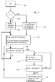
- step 106 the operation of the control device 40 of the drive system of the working vehicle 8 as in the FIG. 2 shown. If, after start-up (step 100), the switch 66 is in the field-driving position (step 102), the controller 40 causes the engine 14 to rotate at a constant speed by the engine controller 64 through a non-illustrated operator Rotary knob can be specified (step 104). The controller 40 then causes the first actuator 62 to move the swing plate 20 of the hydraulic pump 18 to a position of maximum fluid displacement, while the second actuators 52, 56 turn the pivot plates of the hydraulic motors 26, 28 into a position dependent on the desired speed signal from the handle position sensor 48 spend (step 106). The work machine 8 is thus moved forward or backward in a direction of movement.
- the control device 40 acquires the measured values of the torque sensors 70, 72 and compares them with a threshold value stored in the memory device 68 (step 108). If one of the torque values exceeds the threshold value, initially there is no further adjustment of the actuators 52, 56, 62, but the process is repeated (step 106).
- the first actuator 62 is caused to adjust the swash plate 20 of the hydraulic pump 18 in the direction of lower fluid displacement
- the second actuators 52, 56 are caused by the controller 40, the swash plates 54, 58 of the hydraulic motors 26, 28 also in the direction of lower fluid displacement (step 110). This adjustment takes place until the pressures detected by the pressure sensors 46, 60 correspond to an optimum value which corresponds to a maximum efficiency of the hydraulic transmission and is stored in the storage device 68 (step 112).
- the controller 40 may cause the actuators 62, 52, 56 to move the swash plates 20, 54, 58 in the direction of greater fluid displacement at this point, when the detected by means of the pressure sensors 46, 60 pressure is greater than the optimum pressure and the Efficiency is therefore also not optimal.
- the rotational speeds at the shafts 32, 36 should remain constant, which the controller 40 monitors by means of the rotational speed sensors 42, 44 and if necessary readjusted by means of the actuators 52, 56 (step 114). Accordingly, the efficiency of the hydraulic transmission is optimized.
- the described control operations are regularly, z. B. every 0.1 s, repeated (with step 108).
- the controller 40 additionally controls and varies the rotational speed of the internal combustion engine 14 via the engine control 64.
- the load of the internal combustion engine 14 is determined on the basis of its rotational speed (and / or on the basis of the measured value of the engine torque sensors 70, 72) and set to a value at which the overall efficiency of the drive system including the engine 14 and the hydraulic transmission is maximum (step 116).
- the swash plates 20, 54 and 56 are thereby adjusted in the manner described with respect to the field operation (steps 106 ff).
Landscapes
- Engineering & Computer Science (AREA)
- General Engineering & Computer Science (AREA)
- Mechanical Engineering (AREA)
- Automation & Control Theory (AREA)
- Transportation (AREA)
- Control Of Fluid Gearings (AREA)
- Motor Power Transmission Devices (AREA)
Applications Claiming Priority (1)
| Application Number | Priority Date | Filing Date | Title |
|---|---|---|---|
| DE102007058535A DE102007058535A1 (de) | 2007-12-06 | 2007-12-06 | Antriebssystem eines Arbeitsfahrzeugs |
Publications (3)
| Publication Number | Publication Date |
|---|---|
| EP2068045A2 true EP2068045A2 (fr) | 2009-06-10 |
| EP2068045A3 EP2068045A3 (fr) | 2009-09-09 |
| EP2068045B1 EP2068045B1 (fr) | 2011-08-17 |
Family
ID=40336606
Family Applications (1)
| Application Number | Title | Priority Date | Filing Date |
|---|---|---|---|
| EP08169386A Active EP2068045B1 (fr) | 2007-12-06 | 2008-11-19 | Système d'entraînement d'un véhicule de travail |
Country Status (4)
| Country | Link |
|---|---|
| US (1) | US20090145682A1 (fr) |
| EP (1) | EP2068045B1 (fr) |
| DE (1) | DE102007058535A1 (fr) |
| EA (1) | EA017546B1 (fr) |
Cited By (2)
| Publication number | Priority date | Publication date | Assignee | Title |
|---|---|---|---|---|
| CN102549313A (zh) * | 2009-09-03 | 2012-07-04 | 株式会社小松制作所 | 作业车辆 |
| US20220304240A1 (en) * | 2021-03-24 | 2022-09-29 | Deere & Company | Intelligent power allocation systems onboard hybrid combines and associated methods |
Families Citing this family (7)
| Publication number | Priority date | Publication date | Assignee | Title |
|---|---|---|---|---|
| DE102009028175A1 (de) | 2009-02-27 | 2010-09-02 | Deere & Company, Moline | Selbstfahrende Erntemaschine |
| DE102011113485A1 (de) * | 2011-09-15 | 2013-03-21 | Bomag Gmbh | Verfahren zum Ansteuern eines Antriebsstranges eines Fahrzeugs und Vorrichtung zur Durchführung des Verfahrens |
| US8997478B2 (en) * | 2011-09-22 | 2015-04-07 | Deere & Company | Multi-pump system with pump-flow diversion |
| DE102012020984A1 (de) * | 2012-10-25 | 2014-04-30 | Liebherr-Hydraulikbagger Gmbh | Vorrichtung zur Fahrgeschwindigkeitssteuerung/-regelung eines Arbeitsfahrzeugs und Verfahren hierzu |
| DE202013001173U1 (de) * | 2013-02-04 | 2014-05-06 | Liebherr-Components Biberach Gmbh | Hydrauliksystem |
| US9103425B2 (en) | 2013-08-26 | 2015-08-11 | Caterpillar Inc. | Cost configurable hystat drive system |
| DE102020131494A1 (de) | 2020-11-27 | 2022-06-02 | Claas Selbstfahrende Erntemaschinen Gmbh | Verfahren zum Betrieb einer selbstfahrenden Erntemaschine |
Citations (2)
| Publication number | Priority date | Publication date | Assignee | Title |
|---|---|---|---|---|
| DE10211799A1 (de) | 2002-03-16 | 2003-10-02 | Deere & Co | Antriebssystem eines Arbeitsfahrzeugs |
| DE10350308A1 (de) | 2003-10-28 | 2005-05-25 | Zf Friedrichshafen Ag | Verfahren zur Motordrehzahl- und Übersetzungswahl bei einem stufenlosen hydrostatischen Leistungsverzweigungsgetriebe |
Family Cites Families (20)
| Publication number | Priority date | Publication date | Assignee | Title |
|---|---|---|---|---|
| DE2848595A1 (de) * | 1978-11-09 | 1980-05-22 | Bosch Gmbh Robert | Verfahren und vorrichtung zur regelung des abtriebsdrehmomentes eines getriebes |
| US4399886A (en) * | 1980-12-09 | 1983-08-23 | Sundstrand Corporation | Controls for variable displacement motor and motors |
| EP0553348B1 (fr) * | 1990-10-16 | 1997-08-06 | Hitachi Construction Machinery Co., Ltd. | Systeme pour reguler la vitesse de rotation d'un moteur primaire dans un vehicule a commande hydraulique |
| US5873427A (en) * | 1997-04-03 | 1999-02-23 | Caterpillar Inc. | Method and apparatus for controlling a load of an engine associated with a hydrostatic drive system |
| US6321866B1 (en) * | 1998-10-21 | 2001-11-27 | Ag-Chem Equipment Co., Inc. | Hydrostatic power distribution/control logic system |
| DE19931141B4 (de) * | 1999-07-06 | 2005-03-03 | Sauer-Danfoss Holding Aps | Fahrzeug-Antriebsanordnung |
| DE10037676C1 (de) * | 2000-07-26 | 2002-05-23 | Jungheinrich Ag | Vorrichtung zur Regelung eines Antriebssystems für ein Flurförderzeug |
| DE10109775A1 (de) * | 2001-03-01 | 2002-09-12 | Deere & Co | Antriebssystem eines Arbeitsfahrzeugs |
| JP4612972B2 (ja) * | 2001-08-09 | 2011-01-12 | カヤバ工業株式会社 | Hstの制御装置 |
| RU2291064C2 (ru) * | 2002-11-25 | 2007-01-10 | Военный автомобильный институт | Силовая передача транспортного средства с регулируемой величиной кинематического рассогласования |
| RU2264572C1 (ru) * | 2004-04-02 | 2005-11-20 | Открытое акционерное общество "Инновационная фирма "НАМИ-СЕРВИС" | Система управления гидрообъемной трансмиссией многоколесной транспортной машины |
| DE102004016242A1 (de) * | 2004-04-02 | 2005-10-20 | Deere & Co | Antriebssystem eines Arbeitsfahrzeugs |
| JP2005297923A (ja) * | 2004-04-15 | 2005-10-27 | Kanzaki Kokyukoki Mfg Co Ltd | 四輪駆動車両 |
| DE102004061558A1 (de) * | 2004-12-21 | 2006-07-06 | Brueninghaus Hydromatik Gmbh | Verfahren zum Abbremsen eines mittels eines hydrostatischen Getriebes angetriebenen Fahrzeugs sowie ein hydrostatischer Antrieb |
| DE102005038905A1 (de) * | 2005-08-17 | 2007-02-22 | Brueninghaus Hydromatik Gmbh | Verfahren zum Regeln eines Antriebssystems und elektronische Steuereinheit |
| DE102006017792B4 (de) * | 2006-04-18 | 2020-04-23 | Robert Bosch Gmbh | Verfahren und Computerprogramm zum Regeln eines Antriebs |
| DE102006047954A1 (de) * | 2006-09-05 | 2008-03-06 | Robert Bosch Gmbh | Verfahren zum Regeln eines Antriebssystems und eine elektronische Steuereinheit |
| US7797092B2 (en) * | 2006-11-06 | 2010-09-14 | Caterpillar Inc | Method and system for controlling machine power |
| US8000863B2 (en) * | 2007-05-31 | 2011-08-16 | Caterpillar Inc. | Open-loop torque control with closed-loop feedback |
| US7849953B2 (en) * | 2007-11-29 | 2010-12-14 | Caterpillar Paving Products Inc | Control system and method for operating a hydrostatically driven vehicle |
-
2007
- 2007-12-06 DE DE102007058535A patent/DE102007058535A1/de not_active Withdrawn
-
2008
- 2008-11-19 EP EP08169386A patent/EP2068045B1/fr active Active
- 2008-12-03 US US12/327,388 patent/US20090145682A1/en not_active Abandoned
- 2008-12-05 EA EA200802291A patent/EA017546B1/ru not_active IP Right Cessation
Patent Citations (2)
| Publication number | Priority date | Publication date | Assignee | Title |
|---|---|---|---|---|
| DE10211799A1 (de) | 2002-03-16 | 2003-10-02 | Deere & Co | Antriebssystem eines Arbeitsfahrzeugs |
| DE10350308A1 (de) | 2003-10-28 | 2005-05-25 | Zf Friedrichshafen Ag | Verfahren zur Motordrehzahl- und Übersetzungswahl bei einem stufenlosen hydrostatischen Leistungsverzweigungsgetriebe |
Cited By (4)
| Publication number | Priority date | Publication date | Assignee | Title |
|---|---|---|---|---|
| CN102549313A (zh) * | 2009-09-03 | 2012-07-04 | 株式会社小松制作所 | 作业车辆 |
| CN102549313B (zh) * | 2009-09-03 | 2013-05-29 | 株式会社小松制作所 | 作业车辆 |
| US20220304240A1 (en) * | 2021-03-24 | 2022-09-29 | Deere & Company | Intelligent power allocation systems onboard hybrid combines and associated methods |
| US12017633B2 (en) * | 2021-03-24 | 2024-06-25 | Deere & Company | Intelligent power allocation systems onboard hybrid combines and associated methods |
Also Published As
| Publication number | Publication date |
|---|---|
| EA017546B1 (ru) | 2013-01-30 |
| EP2068045B1 (fr) | 2011-08-17 |
| DE102007058535A1 (de) | 2009-06-10 |
| EA200802291A1 (ru) | 2009-06-30 |
| EP2068045A3 (fr) | 2009-09-09 |
| US20090145682A1 (en) | 2009-06-11 |
Similar Documents
| Publication | Publication Date | Title |
|---|---|---|
| EP2068045B1 (fr) | Système d'entraînement d'un véhicule de travail | |
| EP1350658B1 (fr) | Système d'entraînement pour véhicule utilitaire | |
| EP1582389B1 (fr) | Entraînement pour véhicule de travail | |
| EP1293113B1 (fr) | Système de commande d'entraînement d'une prise de force d'un véhicule agricole | |
| DE102007032310A1 (de) | Bedienvorrichtung | |
| EP1038758A2 (fr) | Véhicule dont les roues sont entraínées à des vitesses différentes | |
| EP1052388A2 (fr) | Méthode et procédé pour déterminer la vitesse de rotation d'un engin de travail | |
| EP0885798B1 (fr) | Commande de direction pour véhicules à chenilles | |
| EP2187101B1 (fr) | Système de propulsion pour un engin de construction autopropulsé | |
| DE102016223133A1 (de) | Geschwindigkeitskontrolle einer Erntemaschine | |
| EP1236933B1 (fr) | Système d'entraînement pour véhicule de travail | |
| EP2746212B1 (fr) | Procédé d'ajustement du régime d'un entraînement de grue et entraînement de grue | |
| DE68929357T2 (de) | Mechanisch-hydraulisches Getriebesystem und Steuerverfahren für Leistungsgetriebe mit einem solchen System | |
| EP1795765A2 (fr) | Système hydraulique pour une moissonneuse autotractée | |
| DE112006002950T5 (de) | Baufahrzeug | |
| EP0563515A1 (fr) | Dispositif d'entraînement pour machines de chantier ou véhicules de chantier | |
| EP3832165A2 (fr) | Système d'entraînement pour un véhicule doté d'un engrenage d'entraînement et architecture de commande permettant de commander l'engrenage d'entraînement | |
| BE1030888B1 (de) | Antriebssystem für eine Erntemaschine | |
| DE10214598B4 (de) | Fahrantrieb für eine landwirtschaftliche Erntemaschine mit Steuerung der Fahrgeschwindigkeit bei Straßenfahrten | |
| EP4089302A1 (fr) | Procédé d'aide à l'enclenchement de vitesse des boîtes de vitesses à l'arrêt | |
| DE102015216944A1 (de) | Verfahren zum Betreiben eines hydrostatischen Fahrantriebs und Steuereinrichtung | |
| EP0574737B1 (fr) | Véhicule à propulsion électrique à alimentation par accumulateurs, en particulier Chariot-élévateur | |
| EP3378736B1 (fr) | Système d'entraînement pour véhicules à chenilles et engins de travail à chenilles et procédé de commande d'un système d'entraînement pour véhicules à chenilles et engins de travail à chenilles | |
| EP4428394B1 (fr) | Procédé de commande d'un entraînement hydrostatique | |
| DE102021210154B4 (de) | Verfahren zur steuerung eines mehrmotoren systems |
Legal Events
| Date | Code | Title | Description |
|---|---|---|---|
| PUAI | Public reference made under article 153(3) epc to a published international application that has entered the european phase |
Free format text: ORIGINAL CODE: 0009012 |
|
| AK | Designated contracting states |
Kind code of ref document: A2 Designated state(s): AT BE BG CH CY CZ DE DK EE ES FI FR GB GR HR HU IE IS IT LI LT LU LV MC MT NL NO PL PT RO SE SI SK TR |
|
| AX | Request for extension of the european patent |
Extension state: AL BA MK RS |
|
| PUAL | Search report despatched |
Free format text: ORIGINAL CODE: 0009013 |
|
| AK | Designated contracting states |
Kind code of ref document: A3 Designated state(s): AT BE BG CH CY CZ DE DK EE ES FI FR GB GR HR HU IE IS IT LI LT LU LV MC MT NL NO PL PT RO SE SI SK TR |
|
| AX | Request for extension of the european patent |
Extension state: AL BA MK RS |
|
| 17P | Request for examination filed |
Effective date: 20100309 |
|
| 17Q | First examination report despatched |
Effective date: 20100409 |
|
| AKX | Designation fees paid |
Designated state(s): BE DE FR GB |
|
| GRAP | Despatch of communication of intention to grant a patent |
Free format text: ORIGINAL CODE: EPIDOSNIGR1 |
|
| RIC1 | Information provided on ipc code assigned before grant |
Ipc: F16H 61/42 20100101AFI20110210BHEP |
|
| GRAS | Grant fee paid |
Free format text: ORIGINAL CODE: EPIDOSNIGR3 |
|
| GRAA | (expected) grant |
Free format text: ORIGINAL CODE: 0009210 |
|
| AK | Designated contracting states |
Kind code of ref document: B1 Designated state(s): BE DE FR GB |
|
| REG | Reference to a national code |
Ref country code: GB Ref legal event code: FG4D Free format text: NOT ENGLISH |
|
| REG | Reference to a national code |
Ref country code: DE Ref legal event code: R096 Ref document number: 502008004519 Country of ref document: DE Effective date: 20111020 |
|
| PLBE | No opposition filed within time limit |
Free format text: ORIGINAL CODE: 0009261 |
|
| STAA | Information on the status of an ep patent application or granted ep patent |
Free format text: STATUS: NO OPPOSITION FILED WITHIN TIME LIMIT |
|
| 26N | No opposition filed |
Effective date: 20120521 |
|
| REG | Reference to a national code |
Ref country code: FR Ref legal event code: ST Effective date: 20120731 |
|
| REG | Reference to a national code |
Ref country code: DE Ref legal event code: R097 Ref document number: 502008004519 Country of ref document: DE Effective date: 20120521 |
|
| PG25 | Lapsed in a contracting state [announced via postgrant information from national office to epo] |
Ref country code: FR Free format text: LAPSE BECAUSE OF NON-PAYMENT OF DUE FEES Effective date: 20111130 |
|
| GBPC | Gb: european patent ceased through non-payment of renewal fee |
Effective date: 20121119 |
|
| PG25 | Lapsed in a contracting state [announced via postgrant information from national office to epo] |
Ref country code: GB Free format text: LAPSE BECAUSE OF NON-PAYMENT OF DUE FEES Effective date: 20121119 |
|
| REG | Reference to a national code |
Ref country code: DE Ref legal event code: R084 Ref document number: 502008004519 Country of ref document: DE |
|
| PGFP | Annual fee paid to national office [announced via postgrant information from national office to epo] |
Ref country code: DE Payment date: 20251021 Year of fee payment: 18 |
|
| PGFP | Annual fee paid to national office [announced via postgrant information from national office to epo] |
Ref country code: BE Payment date: 20251127 Year of fee payment: 18 |