EP2068045B1 - Antriebssystem eines Arbeitsfahrzeugs - Google Patents
Antriebssystem eines Arbeitsfahrzeugs Download PDFInfo
- Publication number
- EP2068045B1 EP2068045B1 EP08169386A EP08169386A EP2068045B1 EP 2068045 B1 EP2068045 B1 EP 2068045B1 EP 08169386 A EP08169386 A EP 08169386A EP 08169386 A EP08169386 A EP 08169386A EP 2068045 B1 EP2068045 B1 EP 2068045B1
- Authority
- EP
- European Patent Office
- Prior art keywords
- actuator
- hydraulic
- control device
- internal combustion
- combustion engine
- Prior art date
- Legal status (The legal status is an assumption and is not a legal conclusion. Google has not performed a legal analysis and makes no representation as to the accuracy of the status listed.)
- Active
Links
Images
Classifications
-
- F—MECHANICAL ENGINEERING; LIGHTING; HEATING; WEAPONS; BLASTING
- F16—ENGINEERING ELEMENTS AND UNITS; GENERAL MEASURES FOR PRODUCING AND MAINTAINING EFFECTIVE FUNCTIONING OF MACHINES OR INSTALLATIONS; THERMAL INSULATION IN GENERAL
- F16H—GEARING
- F16H61/00—Control functions within control units of change-speed- or reversing-gearings for conveying rotary motion ; Control of exclusively fluid gearing, friction gearing, gearings with endless flexible members or other particular types of gearing
- F16H61/38—Control of exclusively fluid gearing
- F16H61/40—Control of exclusively fluid gearing hydrostatic
- F16H61/42—Control of exclusively fluid gearing hydrostatic involving adjustment of a pump or motor with adjustable output or capacity
- F16H61/431—Pump capacity control by electro-hydraulic control means, e.g. using solenoid valves
-
- B—PERFORMING OPERATIONS; TRANSPORTING
- B60—VEHICLES IN GENERAL
- B60W—CONJOINT CONTROL OF VEHICLE SUB-UNITS OF DIFFERENT TYPE OR DIFFERENT FUNCTION; CONTROL SYSTEMS SPECIALLY ADAPTED FOR HYBRID VEHICLES; ROAD VEHICLE DRIVE CONTROL SYSTEMS FOR PURPOSES NOT RELATED TO THE CONTROL OF A PARTICULAR SUB-UNIT
- B60W30/00—Purposes of road vehicle drive control systems not related to the control of a particular sub-unit, e.g. of systems using conjoint control of vehicle sub-units
- B60W30/18—Propelling the vehicle
- B60W30/188—Controlling power parameters of the driveline, e.g. determining the required power
- B60W30/1882—Controlling power parameters of the driveline, e.g. determining the required power characterised by the working point of the engine, e.g. by using engine output chart
-
- F—MECHANICAL ENGINEERING; LIGHTING; HEATING; WEAPONS; BLASTING
- F16—ENGINEERING ELEMENTS AND UNITS; GENERAL MEASURES FOR PRODUCING AND MAINTAINING EFFECTIVE FUNCTIONING OF MACHINES OR INSTALLATIONS; THERMAL INSULATION IN GENERAL
- F16H—GEARING
- F16H61/00—Control functions within control units of change-speed- or reversing-gearings for conveying rotary motion ; Control of exclusively fluid gearing, friction gearing, gearings with endless flexible members or other particular types of gearing
- F16H61/38—Control of exclusively fluid gearing
- F16H61/40—Control of exclusively fluid gearing hydrostatic
- F16H61/42—Control of exclusively fluid gearing hydrostatic involving adjustment of a pump or motor with adjustable output or capacity
- F16H61/421—Motor capacity control by electro-hydraulic control means, e.g. using solenoid valves
-
- F—MECHANICAL ENGINEERING; LIGHTING; HEATING; WEAPONS; BLASTING
- F16—ENGINEERING ELEMENTS AND UNITS; GENERAL MEASURES FOR PRODUCING AND MAINTAINING EFFECTIVE FUNCTIONING OF MACHINES OR INSTALLATIONS; THERMAL INSULATION IN GENERAL
- F16H—GEARING
- F16H61/00—Control functions within control units of change-speed- or reversing-gearings for conveying rotary motion ; Control of exclusively fluid gearing, friction gearing, gearings with endless flexible members or other particular types of gearing
- F16H61/38—Control of exclusively fluid gearing
- F16H61/40—Control of exclusively fluid gearing hydrostatic
- F16H61/46—Automatic regulation in accordance with output requirements
- F16H61/47—Automatic regulation in accordance with output requirements for achieving a target output speed
-
- B—PERFORMING OPERATIONS; TRANSPORTING
- B60—VEHICLES IN GENERAL
- B60W—CONJOINT CONTROL OF VEHICLE SUB-UNITS OF DIFFERENT TYPE OR DIFFERENT FUNCTION; CONTROL SYSTEMS SPECIALLY ADAPTED FOR HYBRID VEHICLES; ROAD VEHICLE DRIVE CONTROL SYSTEMS FOR PURPOSES NOT RELATED TO THE CONTROL OF A PARTICULAR SUB-UNIT
- B60W10/00—Conjoint control of vehicle sub-units of different type or different function
- B60W10/04—Conjoint control of vehicle sub-units of different type or different function including control of propulsion units
- B60W10/06—Conjoint control of vehicle sub-units of different type or different function including control of propulsion units including control of combustion engines
-
- B—PERFORMING OPERATIONS; TRANSPORTING
- B60—VEHICLES IN GENERAL
- B60W—CONJOINT CONTROL OF VEHICLE SUB-UNITS OF DIFFERENT TYPE OR DIFFERENT FUNCTION; CONTROL SYSTEMS SPECIALLY ADAPTED FOR HYBRID VEHICLES; ROAD VEHICLE DRIVE CONTROL SYSTEMS FOR PURPOSES NOT RELATED TO THE CONTROL OF A PARTICULAR SUB-UNIT
- B60W10/00—Conjoint control of vehicle sub-units of different type or different function
- B60W10/10—Conjoint control of vehicle sub-units of different type or different function including control of change-speed gearings
- B60W10/101—Infinitely variable gearings
- B60W10/103—Infinitely variable gearings of fluid type
-
- B—PERFORMING OPERATIONS; TRANSPORTING
- B60—VEHICLES IN GENERAL
- B60W—CONJOINT CONTROL OF VEHICLE SUB-UNITS OF DIFFERENT TYPE OR DIFFERENT FUNCTION; CONTROL SYSTEMS SPECIALLY ADAPTED FOR HYBRID VEHICLES; ROAD VEHICLE DRIVE CONTROL SYSTEMS FOR PURPOSES NOT RELATED TO THE CONTROL OF A PARTICULAR SUB-UNIT
- B60W2720/00—Output or target parameters relating to overall vehicle dynamics
- B60W2720/10—Longitudinal speed
-
- F—MECHANICAL ENGINEERING; LIGHTING; HEATING; WEAPONS; BLASTING
- F16—ENGINEERING ELEMENTS AND UNITS; GENERAL MEASURES FOR PRODUCING AND MAINTAINING EFFECTIVE FUNCTIONING OF MACHINES OR INSTALLATIONS; THERMAL INSULATION IN GENERAL
- F16H—GEARING
- F16H61/00—Control functions within control units of change-speed- or reversing-gearings for conveying rotary motion ; Control of exclusively fluid gearing, friction gearing, gearings with endless flexible members or other particular types of gearing
- F16H2061/0015—Transmission control for optimising fuel consumptions
Definitions
- the invention relates to a self-propelled harvester.
- Many work vehicles such as agricultural vehicles and harvesters, use hydraulic drives. They include a hydraulic pump driven by an internal combustion engine and a hydraulic motor connected to the hydraulic fluid-conducting hydraulic motor that drives one or more wheels.
- wheels of the front and rear axles are hydraulically driven by at least one hydraulic motor associated with the axles or the wheels.
- a drive system is in the DE 102 11 799 A1 described.
- the swiveling plate of the adjustable hydraulic pump is actuated by an actuator and a controller controlling it, depending on the position of an operating lever which can be adjusted by the operator, so that a hydraulic flow increasing with the speed predetermined by the operator is generated.
- Two adjustable hydraulic motors are each assigned to the front or rear axle and also comprise adjustable pivot plates by actuators connected to the controller. The position of the swivel plates of the hydraulic motors is controlled on the basis of the output speed of the hydraulic motors and the pressure difference between their inlet and outlet, so that when spinning or against the desired direction backward rotating wheels can be counteracted accordingly.
- a disadvantage is in the drive system after DE 102 11 799 A1 considered that the efficiency of the composed of the hydraulic pump and the hydraulic motors hydraulic transmission is relatively poor, especially in the lower speed range.
- the EP 1 754 643 A1 describes a drive system for a work machine, For example, an excavator comprising an internal combustion engine and a hydrostatic drive unit with a pump and a motor and an electronic control unit.
- the output power of the hydrostatic drive unit is determined, for example, based on the delivery pressure and the delivered volume or the pivot angle of the pump.
- a map of the hydrostatic drive unit the output power and a map of the engine, a low-efficiency operating point for the drive system is determined and set.
- the traction drive and also an adjustable arm are actuated hydraulically, so that the varying speed of the internal combustion engine at different loads is unproblematic.
- this variable speed of the internal combustion engine is not useful in harvesters, because there working units are mechanically driven by the internal combustion engine.
- the problem underlying the invention is seen to provide an improved drive system of a harvester, which does not have the disadvantages mentioned.
- the drive system of the work vehicle which is a self-propelled harvester, includes an internal combustion engine.
- the internal combustion engine drives a hydraulic pump directly or indirectly, ie via interposed mechanical, hydraulic or any other gear.
- the hydraulic pump is connected via a hydraulic line to a hydraulic motor which mechanically drives a propulsion means in engagement with the ground, in particular a wheel or a tracked drive.
- the fluid displacements of the hydraulic pump and the hydraulic motor can be adjusted by a first actuator or a second actuator.
- a control device is connected to both actuators and a speed setting device, which is a setpoint speed signal provides information about the desired target speed at which the work vehicle is to be driven.
- Speed default device can be operated by the operator, or it operates automatically, for example, to achieve a constant Emtegut trimsatz.
- the control device has two degrees of freedom to achieve the desired speed, namely the positions of the actuators with which the fluid displacements of the hydraulic pump and the hydraulic motor are changed.
- One of the degrees of freedom is occupied by the desired set speed, while the present invention provides for taking advantage of the other degree of freedom to achieve optimum (i.e., maximum) overall efficiency of the hydraulic transmission consisting of the hydraulic pump and the hydraulic motor.
- the control device is additionally connected to a motor control of the internal combustion engine.
- the controller also changes the speed of the internal combustion engine in a manner that optimizes the overall efficiency of the entire drive system, including the internal combustion engine.
- This variation of the rotational speed of the internal combustion engine is provided in road driving operation, which is recognizable by means of a switch designed for switching between the field operation and the road driving operation.
- a switch designed for switching between the field operation and the road driving operation.
- it is provided to fix the speed of the internal combustion engine by an operator or an automatic control based on suitable sensor values for the respective crop throughput, in order to ensure suitable rotational speeds for the working units of the harvesting machine, such as threshing and separating devices for combine harvesters or to provide shredders and conveyors for forage harvesters.
- detection of torque output from the hydraulic motor can be performed by means of a torque sensor serve, which can be used to determine the most suitable for the provision of the required torque or power speed of the internal combustion engine.
- the efficiency of hydraulic pumps and hydraulic motors depends in particular on the pressure difference between the inlet and the outlet, which in turn is in connection with the predetermined by the respective actuator by adjusting the swash plate fluid displacement.
- the efficiency of the hydraulic transmission increases with increasing pressure to a specific value for the hydraulic pump or the hydraulic motor. It is therefore advisable to command the hydraulic pump and the hydraulic motor to these values so that they operate with the best efficiency by connecting the control device with a pressure sensor arranged to detect the pressure prevailing on the output side of the hydraulic pump and adjusting the actuators in such a way that that a pressure is achieved at the pressure sensor, wherein the overall efficiency of the Hydraulic pump and the hydraulic motor is maximum.
- This pressure can be stored in a memory device connected to the controller.
- the fluid displacement is reduced from a maximum fluid displacement until the optimum pressure is present.
- a fluid displacement causing greater than optimal pressure it will increase until the optimum pressure is reached.
- This optimum pressure may depend on the desired speed of the hydraulic motor, so that the speed of the hydraulic motor or the desired speed for selecting the pressure to be controlled can be used.
- suitable curves, formulas or tables can be stored and retrieved in a memory device of the control device.
- the swing angle of the hydraulic pump can be adjusted to the maximum possible value or an underlying value, but still sufficient to provide the required torque and offers better efficiency than the maximum tilt angle.
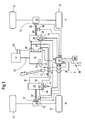
- FIG. 1 an embodiment of a drive system according to the invention is shown schematically.
- a work vehicle 8 has a frame (not shown) or a self-supporting chassis which rests on front propulsion means 10 and rear propulsion means 12 in the form of wheels which are in engagement with the ground.
- the rear propulsion means 12 are generally steerable, while the front propulsion means 10 are of larger diameter than the rear propulsion means 12 and support the greater part of the weight of the work vehicle 8, in particular when it is a harvester in the form of a combine harvester or self-propelled forage harvester.
- the drive system includes an internal combustion engine 14 in the form of a diesel engine. Via a shaft 16, the internal combustion engine 14 drives a hydraulic pump 18, the fluid displacement of which can be changed by a swashplate 20 whose position is controlled mechanically by a first actuator 62.
- the hydraulic pump 18 has an outlet connected by lines 24 to the inlet of a first hydraulic motor 26 and the inlet of a second hydraulic motor 28.
- An inlet of the hydraulic pump 18 is connected via lines 30 to the outlet of the first hydraulic motor 26 and the outlet of the second hydraulic motor 28. If the working vehicle 8 is a self-propelled harvesting machine, the internal combustion engine 14 also drives its crop processing devices.
- the first hydraulic motor 26 drives the two rear wheels 12 via a first drive shaft 32 and a first self-locking differential gear 34.
- the second hydraulic motor 28 drives the two front wheels 10 via a second drive shaft 36 and a second self-locking differential 38.
- the first hydraulic motor 26 may optionally be switched on and off, so that a four-wheel drive is selectable only in special operating situations in which a better traction is needed.
- a manual transmission with different, selectable gear ratios may be present, which in the FIG. 1 is not shown for reasons of clarity.
- a control device 40 is connected to a first rotational speed sensor 42, a second rotational speed sensor 44 and a first pressure sensor 46.
- the first speed sensor 42 is disposed adjacent to the first drive shaft 32 and outputs a pulse at each revolution (or several times during one revolution) of the first drive shaft 32. It may include an optical or magnetic sensor cooperating with corresponding markers or permanent magnets attached to the first drive shaft 32.
- the second speed sensor 44 is disposed adjacent to the second drive shaft 36 and emits a pulse at each revolution (or several times during one revolution) of the second drive shaft 36. It may include an optical or magnetic sensor cooperating with corresponding markers or permanent magnets attached to the second drive shaft 36.
- the pressure sensor 46 is disposed in the interior of the first hydraulic motor 26 and detects the pressure applied to the outlet of the first hydraulic motor 26.
- a drive lever position sensor 48 detects the position of a drive lever 22 attached to the operator workstation of the work vehicle 8. The drive lever position sensor 48 detects the current position of the drive lever 22 optically or magnetically.
- the control device 40 is connected to a second electromechanical actuator 52, which is set up for adjusting a swash plate 54 of the first hydraulic motor 26. Information about the position of the actuator 52 can be fed back to the control device 40. If a stepper motor is used as actuator 52, this feedback is unnecessary. It is also basically not necessary, since the operating state of the first hydraulic motor 26 is detected.
- the control device 40 receives from the second speed sensor 44, a measured value with respect to the rotational speed of the front wheels 10. In addition, the controller 40 receives from the first speed sensor 42 information about the rotational speed of the rear wheels 12th
- the second hydraulic motor 28 has a variable by a second electromechanical actuator 56 and an adjustable swash plate 58 fluid displacement, and it is associated with a second pressure sensor 60, the pressure at the outlet of second hydraulic motor 28 measures.
- the controller 40 is connected to the pressure sensor 60 and the actuator 56.
- a first actuator 62 is provided for adjusting the swash plate 20 of the hydraulic pump 18, which operates electromechanically or electro-hydraulically and is controlled by the control device 40. It is conceivable to additionally supply the control device 40 with information about the respective position of the first actuator 62. However, such a feedback is not absolutely necessary, since a stepper motor can be used, and since the control device also because of the feedback, in particular via the speed sensors 42, 44 and the pressure sensors 46, 60 information about the operating state of the hydraulic pump 18 is present.
- the control device 40 receives from the throttle lever position sensor 48 a target speed signal with regard to the position of the driving lever 22 (serving as a speed setting device).
- an engine control unit 64 connected to the control device 40, which determines the rotational speed of the internal combustion engine 14.
- a connected to the controller 40 switch 66 is used to switch between a field operation (position F) and a road operation (position S).
- the controller 40 is connected to a memory device 68 and two torque sensors 70, 72, which detect the torque in the shafts 32 and 36, respectively.
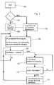
- step 106 the operation of the control device 40 of the drive system of the working vehicle 8 as in the FIG. 2 shown. If, after start-up (step 100), the switch 66 is in the field-driving position (step 102), the controller 40 causes the engine 14 to rotate at a constant speed by the engine controller 64 through a non-illustrated operator Rotary knob can be specified (step 104). The controller 40 then causes the first actuator 62 to move the swing plate 20 of the hydraulic pump 18 to a position of maximum fluid displacement, while the second actuators 52, 56 turn the pivot plates of the hydraulic motors 26, 28 into a position dependent on the desired speed signal from the handle position sensor 48 spend (step 106). The work machine 8 is thus moved forward or backward in a direction of movement.
- the control device 40 acquires the measured values of the torque sensors 70, 72 and compares them with a threshold value stored in the memory device 68 (step 108). If one of the torque values exceeds the threshold value, initially there is no further adjustment of the actuators 52, 56, 62, but the process is repeated (step 106).
- the first actuator 62 is caused to adjust the swash plate 20 of the hydraulic pump 18 in the direction of lower fluid displacement
- the second actuators 52, 56 are caused by the controller 40, the swash plates 54, 58 of the hydraulic motors 26, 28 also in the direction of lower fluid displacement (step 110). This adjustment takes place until the pressures detected by the pressure sensors 46, 60 correspond to an optimum value which corresponds to a maximum efficiency of the hydraulic transmission and is stored in the storage device 68 (step 112).
- the controller 40 may cause the actuators 62, 52, 56 to move the swash plates 20, 54, 58 in the direction of greater fluid displacement at this point, when the detected by means of the pressure sensors 46, 60 pressure is greater than the optimum pressure and the Efficiency is therefore also not optimal.
- the rotational speeds at the shafts 32, 36 should remain constant, which the controller 40 monitors by means of the rotational speed sensors 42, 44 and if necessary readjusted by means of the actuators 52, 56 (step 114). Accordingly, the efficiency of the hydraulic transmission is optimized.
- the described control operations are regularly, z. B. every 0.1 s, repeated (with step 108).
- the controller 40 additionally controls and varies the rotational speed of the internal combustion engine 14 via the engine control 64.
- the load of the internal combustion engine 14 is determined on the basis of its rotational speed (and / or on the basis of the measured value of the engine torque sensors 70, 72) and set to a value at which the overall efficiency of the drive system including the engine 14 and the hydraulic transmission is maximum (step 116).
- the swash plates 20, 54 and 56 are thereby adjusted in the manner described with respect to the field operation (steps 106 ff).
Landscapes
- Engineering & Computer Science (AREA)
- General Engineering & Computer Science (AREA)
- Mechanical Engineering (AREA)
- Automation & Control Theory (AREA)
- Transportation (AREA)
- Control Of Fluid Gearings (AREA)
- Motor Power Transmission Devices (AREA)
Description
- Die Erfindung betrifft eine selbstfahrende Erntemaschine.
- Bei vielen Arbeitsfahrzeugen, wie landwirtschaftlichen Fahrzeugen und Erntemaschinen, werden hydraulische Antriebe eingesetzt. Sie umfassen eine durch einen Verbrennungsmotor angetriebene Hydraulikpumpe und einen mit der Pumpe hydraulikflüssigkeitsleitend verbundenen Hydraulikmotor, der ein Rad oder mehrere Räder antreibt. Bei manchen Fahrzeugen werden Räder der Vorder- und Hinterachse durch jeweils mindestens einen, den Achsen oder den Rädern zugeordneten Hydraulikmotor hydraulisch angetrieben.
- Ein Antriebssystem wird in der
DE 102 11 799 A1 beschrieben. Die Schwenkplatte der verstellbaren Hydraulikpumpe wird durch einen Aktor und eine diesen kontrollierende Steuerung abhängig von der Stellung eines durch den Bediener verstellbaren Fahrhebels angesteuert, so dass ein mit der durch den Bediener vorgegebenen Geschwindigkeit wachsender Hydraulikfluss erzeugt wird. Zwei verstellbare Hydraulikmotore sind jeweils der Vorder- oder Hinterachse zugeordnet und umfassen ebenfalls durch mit der Steuerung verbundene Aktoren verstellbare Schwenkplatten. Die Position der Schwenkplatten der Hydraulikmotore wird anhand der Ausgangsdrehzahl der Hydraulikmotore und des Druckunterschieds zwischen ihrem Ein- und Auslass angesteuert, so dass bei durchdrehenden oder sich entgegen der gewünschten Richtung rückwärts drehenden Rädern entsprechend gegengesteuert werden kann. - Als nachteilig wird bei dem Antriebssystem nach
DE 102 11 799 A1 angesehen, dass der Wirkungsgrad des sich aus der Hydraulikpumpe und den Hydraulikmotoren zusammensetzenden hydraulischen Getriebes insbesondere im unteren Geschwindigkeitsbereich relativ schlecht ist. - Die
EP 1 754 643 A1 beschreibt ein Antriebssystem für eine Arbeitsmaschine, beispielsweise einen Bagger, das einen Verbrennungsmotor und eine hydrostatische Antriebseinheit mit einer Pumpe und einem Motor sowie eine elektronische Steuereinheit umfasst. Zunächst wird die Abgabeleistung der hydrostatischen Antriebseinheit ermittelt, beispielsweise anhand des Förderdrucks und des geförderten Volumens oder des Schwenkwinkels der Pumpe. Unter Berücksichtigung eines Kennfelds der hydrostatischen Antriebseinheit, der Abgabeleistung und eines Kennfelds des Verbrennungsmotors wird ein wirkungsgradgünstigster Betriebspunkt für das Antriebssystem ermittelt und eingestellt. Hier werden der Fahrantrieb und auch ein verstellbarer Arm hydraulisch betätigt, sodass die bei unterschiedlichen Belastungen variierende Drehzahl des Verbrennungsmotors unproblematisch ist. Diese veränderbare Drehzahl des Verbrennungsmotors ist bei Erntemaschinen jedoch nicht sinnvoll, denn dort werden Arbeitsaggregate mechanisch vom Verbrennungsmotor angetrieben. - Das der Erfindung zu Grunde liegende Problem wird darin gesehen, ein verbessertes Antriebssystem einer Erntemaschine bereitzustellen, das die genannten Nachteile nicht aufweist.
- Dieses Problem wird erfindungsgemäß durch die Lehre des Patentanspruchs 1 gelöst, wobei in den weiteren Patentansprüchen Merkmale aufgeführt sind, die die Lösung in vorteilhafter Weise weiterentwickeln.
- Das Antriebssystem des Arbeitsfahrzeugs, bei dem es sich um eine selbstfahrende Erntemaschine handelt, umfasst einen Verbrennungsmotor. Der Verbrennungsmotor treibt eine Hydraulikpumpe direkt oder indirekt, d.h. über dazwischen geschaltete mechanische, hydraulische oder beliebige andere Getriebe an. Die Hydraulikpumpe steht über eine Hydraulikleitung mit einem Hydraulikmotor in Verbindung, der ein im Eingriff mit dem Erdboden befindliches Vortriebsmittel, insbesondere ein Rad oder ein Raupenlaufwerk, mechanisch antreibt. Die Fluidverdrängungen der Hydraulikpumpe und des Hydraulikmotors sind durch einen ersten Aktor bzw. einen zweiten Aktor verstellbar. Eine Steuereinrichtung ist mit beiden Aktoren und einer Geschwindigkeitsvorgabeeinrichtung verbunden, die ein Sollgeschwindigkeitssignal bereitstellt, das eine Information über die gewünschte Sollgeschwindigkeit enthält, mit dem das Arbeitsfahrzeug angetrieben werden soll. Die
- Geschwindigkeitsvorgabeeinrichtung kann durch den Bediener betätigt werden, oder sie arbeitet automatisch, um beispielsweise einen konstanten Emtegutdurchsatz zu erzielen. Die Steuereinrichtung hat zwei Freiheitsgrade, um die Sollgeschwindigkeit zu erzielen, nämlich die Positionen der Aktoren, mit denen die Fluidverdrängungen der Hydraulikpumpe und des Hydraulikmotors verändert werden. Einer der Freiheitsgrade wird durch die gewünschte Sollgeschwindigkeit belegt, während die vorliegende Erfindung vorsieht, den anderen Freiheitsgrad derart auszunutzen, dass man einen optimalen (d. h. maximalen) Gesamtwirkungsgrad des aus der Hydraulikpumpe und dem Hydraulikmotor bestehenden hydraulischen Getriebes erzielt.
- Die Steuereinrichtung ist zusätzlich mit einer Motorsteuerung des Verbrennungsmotors verbunden. Die Steuereinrichtung verändert auch die Drehzahl des Verbrennungsmotors in einer Weise, dass der Gesamtwirkungsgrad des gesamten Antriebssystems einschließlich des Verbrennungsmotors optimiert wird.
- Diese Variation der Drehzahl des Verbrennungsmotors ist im Straßenfahrbetrieb vorgesehen, der anhand eines zur Umschaltung zwischen dem Feldbetrieb und dem Straßenfahrbetrieb ausgelegten Schalters erkennbar ist. Während des Feldbetriebs ist es hingegen vorgesehen, die Drehzahl des Verbrennungsmotors durch einen Bediener oder eine auf geeigneten Sensorwerten für den jeweiligen Erntegutdurchsatz basierende selbsttätige Steuerung fest vorgebbar und konstant zu halten, um geeignete Drehzahlen für die Arbeitsaggregate der Erntemaschine, wie Dresch- und Trenneinrichtungen für Mähdrescher oder Häcksel- und Fördereinrichtungen für Feldhäcksler bereitzustellen.
- Auf diese Weise erhält man eine Verbesserung des Wirkungsgrads des Antriebssystems und eine Verminderung des Kraftstoffbedarfs.
- Als weiterer Eingangsparameter kann, wenn die Drehzahl des Verbrennungsmotors in einer Weise verändert wird, dass der Gesamtwirkungsgrad des gesamten Antriebssystems einschließlich des Verbrennungsmotors optimiert wird, eine Erfassung des vom Hydraulikmotor abgegebenen Drehmoments mittels eines Drehmomentsensors dienen, die zur Bestimmung der zur Bereitstellung des benötigten Drehmoments bzw. Leistung geeignetesten Drehzahl des Verbrennungsmotors herangezogen werden kann.
- Der Wirkungsgrad von Hydraulikpumpen und Hydraulikmotoren hängt insbesondere von der Druckdifferenz zwischen dem Einlass und dem Auslass ab, die wiederum im Zusammenhang mit der durch den jeweiligen Aktor durch Verstellen der Schwenkscheibe vorgegebenen Fluidverdrängung steht. Im Allgemeinen steigt der Wirkungsgrad des hydraulischen Getriebes mit steigendem Druck bis auf einen für die Hydraulikpumpe bzw. den Hydraulikmotor spezifischen Wert an. Es bietet sich daher an, die Hydraulikpumpe und den Hydraulikmotor auf diese Werte zu kommandieren, so dass diese mit dem besten Wirkungsgrad arbeiten, indem die Steuereinrichtung mit einem zur Erfassung des ausgangseitig an der Hydraulikpumpe herrschenden Drucks eingerichteten Drucksensor verbunden wird und die Aktoren derart verstellt, dass ein Druck am Drucksensor erzielt wird, bei dem der Gesamtwirkungsgrad der Hydraulikpumpe und des Hydraulikmotors maximal ist. Dieser Druck kann in einer mit der Steuerung verbundenen Speichereinrichtung abgelegt werden. Demnach wird die Fluidverdrängung ausgehend von einer maximalen Fluidverdrängung solange vermindert, bis der optimale Druck vorhanden ist. Analog wird sie ausgehend von einer zu geringen Fluidverdrängung, die einen größeren als den optimalen Druck bewirkt, vergrößert, bis der optimale Druck erreicht ist. Dieser optimale Druck kann von der gewünschten Drehzahl des Hydraulikmotors abhängen, so dass die Drehzahl des Hydraulikmotors bzw. die Sollgeschwindigkeit zur Auswahl des anzusteuernden Drucks mit herangezogen werden kann. Dazu können geeignete Kurven, Formeln oder Tabellen in einer Speichereinrichtung der Steuereinrichtung abgelegt und abgerufen werden.
- Weiterhin wird vorgeschlagen, das vom Hydraulikmotor abgegebene Drehmoment durch einen Drehmomentsensor zu erfassen. Dadurch wird es möglich, Situationen zu erkennen, in denen der von der Hydraulikpumpe bereitgestellte Druck nicht mehr hinreicht, das Drehmoment am Ausgang des Hydraulikmotors bereitzustellen. In derartigen Fällen, in denen das erfasste Drehmoment einen Schwellenwert übersteigt, wird die Steuereinrichtung den ersten und zweiten Aktor veranlassen, die Fluidverdrängungen der Hydraulikpumpe und des Hydraulikmotors zu vergrößern, um (allerdings auf Kosten des Wirkungsgrads) das benötigte Drehmoment bereitstellen zu können. Der Schwenkwinkel der Hydraulikpumpe kann bis zum maximal möglichen Wert oder einen darunter liegenden Wert verstellt werden, der aber noch zur Bereitstellung des geforderten Drehmoments hinreicht und einen bessern Wirkungsgrad als der maximale Schwenkwinkel bietet.
- In der Zeichnung ist ein nachfolgend näher beschriebenes Ausführungsbeispiel der Erfindung dargestellt. Es zeigt:
- Fig. 1
- ein Schema eines erfindungsgemäßen Antriebssystems, und
- Fig. 2
- ein Flussdiagramm, nach dem die Steuerungseinrichtung der
Figur 1 arbeitet. - In der
Figur 1 ist eine Ausführungsform eines erfindungsgemäßen Antriebssystems schematisch dargestellt. Ein Arbeitsfahrzeug 8 weist einen (nicht dargestellten) Rahmen oder ein selbsttragendes Chassis auf, der sich auf vorderen Vortriebsmitteln 10 und hinteren Vortriebsmitteln 12 in Form von Rädern abstützt, die sich im Eingriff mit dem Erdboden befinden. Die hinteren Vortriebsmittel 12 sind in der Regel lenkbar, während die vorderen Vortriebsmittel 10 größeren Durchmessers als die hinteren Vortriebsmittel 12 sind und den größeren Teil des Gewichts des Arbeitsfahrzeugs 8 abstützen, insbesondere wenn es sich um eine Erntemaschine in Form eines Mähdreschers oder selbstfahrenden Feldhäckslers handelt. - Das Antriebssystem umfasst einen Verbrennungsmotor 14 in Form eines Dieselmotors. Über eine Welle 16 treibt der Verbrennungsmotor 14 eine Hydraulikpumpe 18 an, deren Fluidverdrängung durch eine Schwenkscheibe 20 veränderbar ist, deren Position mechanisch durch einen ersten Aktor 62 gesteuert wird. Die Hydraulikpumpe 18 weist einen Auslass auf, der durch Leitungen 24 mit dem Einlass eines ersten Hydraulikmotors 26 und dem Einlass eines zweiten Hydraulikmotors 28 verbunden ist. Ein Einlass der Hydraulikpumpe 18 ist über Leitungen 30 mit dem Auslass des ersten Hydraulikmotors 26 und dem Auslass des zweiten Hydraulikmotors 28 verbunden. Der Verbrennungsmotor 14 treibt, falls das Arbeitsfahrzeug 8 eine selbstfahrende Erntemaschine ist, auch deren Gutbearbeitungseinrichtungen an.
- Der erste Hydraulikmotor 26 treibt über eine erste Antriebswelle 32 und ein erstes selbstsperrendes Differenzialgetriebe 34 die beiden hinteren Räder 12 an. Der zweite Hydraulikmotor 28 treibt über eine zweite Antriebswelle 36 und ein zweites selbstsperrendes Differenzialgetriebe 38 die beiden vorderen Räder 10 an. Der erste Hydraulikmotor 26 kann wahlweise ein- und ausschaltbar sein, so dass ein Vierradantrieb nur in besonderen Betriebssituationen auswählbar ist, in denen ein besseres Traktionsvermögen benötigt wird. Zwischen dem zweiten Hydraulikmotor 28 und dem zweiten Differenzialgetriebe 38 kann ein Schaltgetriebe mit unterschiedlichen, wählbaren Übersetzungsstufen vorhanden sein, das in der
Figur 1 aus Gründen der Übersichtlichkeit nicht eingezeichnet ist. - Eine Steuereinrichtung 40 ist mit einem ersten Drehzahlsensor 42, einem zweiten Drehzahlsensor 44 und einem ersten Drucksensor 46 verbunden. Der erste Drehzahlsensor 42 ist der ersten Antriebswelle 32 benachbart angeordnet und gibt bei jeder Umdrehung (oder mehrmals während einer Umdrehung) der ersten Antriebswelle 32 einen Impuls ab. Er kann einen optischen oder magnetischen Sensor umfassen, der mit entsprechenden Markierungen oder Permanentmagneten zusammenwirkt, die an der ersten Antriebswelle 32 befestigt sind. Der zweite Drehzahlsensor 44 ist der zweiten Antriebswelle 36 benachbart angeordnet und gibt bei jeder Umdrehung (oder mehrmals während einer Umdrehung) der zweiten Antriebswelle 36 einen Impuls ab. Er kann einen optischen oder magnetischen Sensor umfassen, der mit entsprechenden Markierungen oder Permanentmagneten zusammenwirkt, die an der zweiten Antriebswelle 36 befestigt sind. Der Drucksensor 46 ist im Innenraum des ersten Hydraulikmotors 26 angeordnet und erfasst den Druck, der am Auslass des ersten Hydraulikmotors 26 anliegt. Ein Fahrhebelstellungssensor 48 erfasst die Position eines am Bedienerarbeitsplatz des Arbeitsfahrzeugs 8 angebrachten Fahrhebels 22. Der Fahrhebelstellungssensor 48 erfasst die aktuelle Stellung des Fahrhebels 22 optisch oder magnetisch.
- Die Steuereinrichtung 40 ist mit einem zweiten elektromechanischen Aktor 52 verbunden, der zur Verstellung einer Schwenkscheibe 54 des ersten Hydraulikmotors 26 eingerichtet ist. Eine Information über die Stellung des Aktors 52 kann an die Steuereinrichtung 40 zurückgekoppelt werden. Findet ein Schrittmotor als Aktor 52 Verwendung, erübrigt sich diese Rückkopplung. Sie ist auch grundsätzlich nicht erforderlich, da der Betriebszustand des ersten Hydraulikmotors 26 erfasst wird.
- Die Steuereinrichtung 40 erhält vom zweiten Drehzahlsensor 44 einen Messwert hinsichtlich der Drehzahl der vorderen Räder 10. Außerdem erhält die Steuereinrichtung 40 vom ersten Drehzahlsensor 42 eine Information über die Drehzahl der hinteren Räder 12.
- Auch der zweite Hydraulikmotor 28 weist eine durch einen zweiten elektromechanischen Aktor 56 und eine verstellbare Schwenkscheibe 58 veränderbare Fluidverdrängung auf, und ihm ist ein zweiter Drucksensor 60 zugeordnet, der den Druck am Auslass des zweiten Hydraulikmotors 28 misst. Die Steuereinrichtung 40 ist mit dem Drucksensor 60 und dem Aktor 56 verbunden.
- Weiterhin ist zur Verstellung der Schwenkscheibe 20 der Hydraulikpumpe 18 ein erster Aktor 62 vorgesehen, der elektromechanisch oder elektrohydraulisch arbeitet und durch die Steuereinrichtung 40 gesteuert wird. Es ist denkbar, der Steuereinrichtung 40 zusätzlich eine Information über die jeweilige Stellung des ersten Aktors 62 zuzuführen. Eine derartige Rückführung ist aber nicht unbedingt notwendig, da ein Schrittmotor verwendet werden kann, und da der Steuereinrichtung auch wegen der Rückkopplung insbesondere über die Drehzahlsensoren 42, 44 und die Drucksensoren 46, 60 eine Information über den Betriebszustand der Hydraulikpumpe 18 vorliegt. Die Steuereinrichtung 40 erhält vom Fahrhebelstellungssensor 48 ein Sollgeschwindigkeitssignal hinsichtlich der Stellung des (als Geschwindigkeitsvorgabeeinrichtung dienenden) Fahrhebels 22.
- Dem Verbrennungsmotor 14 ist eine mit der Steuereinrichtung 40 verbundene Motorsteuerung 64 zugeordnet, welche die Drehzahl des Verbrennungsmotors 14 bestimmt. Ein mit der Steuereinrichtung 40 verbundener Schalter 66 dient zur Umstellung zwischen einem Feldbetrieb (Stellung F) und einem Straßenbetrieb (Stellung S). Schließlich ist die Steuerung 40 mit einer Speichereinrichtung 68 und zwei Drehmomentsensoren 70, 72 verbunden, welche das Drehmoment in den Wellen 32 bzw. 36 erfassen.
- Nach alledem erfolgt die Arbeitsweise der Steuereinrichtung 40 des Antriebssystems des Arbeitsfahrzeugs 8 wie in der
Figur 2 dargestellt. Befindet sich nach dem Start (Schritt 100) der Schalter 66 in der Stellung für Feldbetrieb (Schritt 102), veranlasst die Steuereinrichtung 40 den Verbrennungsmotor 14 mittels der Motorsteuerung 64, sich mit einer konstanten Drehzahl zu drehen, die durch den Bediener über einen nicht dargestellten Drehknopf vorgebbar sein kann (Schritt 104). Die Steuereinrichtung 40 veranlasst dann den ersten Aktor 62, die Schwenkplatte 20 der Hydraulikpumpe 18 in eine Stellung maximaler Fluidverdrängung zu bewegen, während die zweiten Aktoren 52, 56 die Schwenkplatten der Hydraulikmotoren 26, 28 in eine vom Sollgeschwindigkeitssignal vom Fahrhebelstellungssensor 48 abhängige Stellung verbringen (Schritt 106). Die Arbeitsmaschine 8 wird demnach in eine Bewegungsrichtung vorwärts oder rückwärts bewegt. Die Steuereinrichtung 40 erfasst die Messwerte der Drehmomentsensoren 70, 72 und vergleicht sie mit einem in der Speichereinrichtung 68 abgelegten Schwellenwert (Schritt 108). Überschreitet einer der Drehmomentwerte den Schwellenwert, erfolgt zunächst keine weitere Verstellung der Aktoren 52, 56, 62, sondern der Vorgang wird wiederholt (Schritt 106). - Unterschreiten die Drehmomente in den Wellen 32, 36 den Schwellenwert, besteht die Möglichkeit, die Schwenkscheiben 20, 54 und 58 in kleinere Schwenkwinkel zu verstellen, die einen besseren Wirkungsgrad des hydraulischen Getriebes ermöglichen. Demnach wird der erste Aktor 62 veranlasst, die Schwenkscheibe 20 der Hydraulikpumpe 18 in Richtung einer geringeren Fluidverdrängung zu verstellen, und die zweiten Aktoren 52, 56 werden durch die Steuerung 40 veranlasst, die Schwenkscheiben 54, 58 der Hydraulikmotoren 26, 28 ebenfalls in Richtung einer geringeren Fluidverdrängung zu verstellen (Schritt 110). Diese Verstellung erfolgt, bis die mittels der Drucksensoren 46, 60 erfassten Drücke einem Optimalwert entsprechen, der einem maximalen Wirkungsgrad des hydraulischen Getriebes entspricht und in der Speichereinrichtung 68 abgelegt ist (Schritt 112). Analog kann die Steuereinrichtung 40 an dieser Stelle die Aktoren 62, 52, 56 veranlassen, die Schwenkscheiben 20, 54, 58 in Richtung einer größeren Fluidverdrängung zu bewegen, wenn der mittels der Drucksensoren 46, 60 erfasste Druck größer als der optimale Druck ist und der Wirkungsgrad demnach ebenfalls nicht optimal ist.
- Während dieser Verstellungen sollen die Drehzahlen an den Wellen 32, 36 konstant bleiben, was die Steuerung 40 mittels der Drehzahlsensoren 42, 44 überwacht und wenn nötig mittels der Aktoren 52, 56 nachregelt (Schritt 114). Demnach wird der Wirkungsgrad des hydraulischen Getriebes optimiert. Die beschriebenen Regelvorgänge werden regelmäßig, z. B. alle 0,1 s, wiederholt (mit Schritt 108).
- Steht der Schalter 66 in der Stellung für Straßenbetrieb (Schritt 102), kontrolliert und variiert die Steuerung 40 zusätzlich die Drehzahl des Verbrennungsmotors 14 über die Motorsteuerung 64. Dabei wird jeweils die Belastung des Verbrennungsmotors 14 anhand dessen Drehzahl (und/ oder anhand des Messwertes der Drehmomentsensoren 70, 72) erfasst und auf einen Wert eingestellt, bei dem der Gesamtwirkungsgrad des Antriebssystems einschließlich des Verbrennungsmotors 14 und des hydraulischen Getriebes maximal ist (Schritt 116). Die Schwenkscheiben 20, 54 und 56 werden dabei in der bezüglich des Feldbetriebs beschriebenen Weise verstellt (Schritte 106 ff).
Claims (4)
- Selbstfahrende Erntemaschine mit einem Antriebssystem mit:einem Verbrennungsmotor (14),einer mit dem Verbrennungsmotor (14) in Antriebsverbindung stehenden Hydraulikpumpe (18), deren Fluidverdrängung durch einen ersten Aktor (62) veränderbar ist,einem hydraulikflüssigkeitsleitend mit der Hydraulikpumpe (18) verbundenen Hydraulikmotor (26, 28), dessen Fluidverdrängung durch einen zweiten Aktor (52, 56) veränderbar ist und der mit wenigstens einem im Eingriff mit dem Erdboden befindlichen Vortriebsmittel (10, 12) in Antriebsverbindung steht,und einer Steuereinrichtung (40), die mit einer Motorsteuerung (64) des Verbrennungsmotors (14), dem ersten Aktor (62), dem zweiten Aktor (52, 56) und einer zur Erzeugung eines Sollgeschwindigkeitssignals ausgelegten Geschwindigkeitsvorgabeeinrichtung (22) verbunden und betreibbar ist, den ersten Aktor (62) und den zweiten Aktor (52, 56) derart anzusteuern, dass das Vortriebsmittel (10, 12) mit einer durch die Geschwindigkeitsvorgabeeinrichtung (22) vorgegebenen Sollgeschwindigkeit angetrieben wird,wobei die Steuereinrichtung (40) betreibbar ist, den ersten Aktor (62) und den zweiten Aktor (52, 56) in einer Weise anzusteuern, dass der Gesamtwirkungsgrad der Hydraulikpumpe (18) und des Hydraulikmotors (26, 28) maximal ist,die Steuereinrichtung (40) mit einem Schalter (66) zur Umstellung zwischen Feldbetrieb und Straßenfahrbetrieb verbunden ist,und die Drehzahl des Verbrennungsmotors (14) bei auf Feldbetrieb gestelltem Schalter (66) durch einen Bediener oder eine auf Sensorwerten für den jeweiligen Emtegutdurchsatz basierende selbsttätige Steuerung fest vorgebbar und konstant ist, um geeignete Drehzahlen für die Arbeitsaggregate der Erntemaschine bereitzustellen, während die Steuereinrichtung (40) bei auf Straßenfahrbetrieb gestellten Schalter (66) betreibbar ist, auch die Drehzahl des Verbrennungsmotors (14) derart zu variieren, dass ein maximaler Gesamtwirkungsgrad des Antriebssystems erzielt wird.
- Erntemaschine nach Anspruch 1, dadurch gekennzeichnet, dass die Steuereinrichtung (40) mit einem zur Erfassung des ausgangseitig an der Hydraulikpumpe (18) herrschenden Drucks eingerichteten Drucksensor (46, 60) verbunden und betreibbar ist, die Aktoren (62, 52, 56) derart zu verstellen, dass ein Druck am Drucksensor (46, 60) erzielt wird, bei dem der Gesamtwirkungsgrad der Hydraulikpumpe (18) und des Hydraulikmotors (26, 28) maximal ist.
- Erntemaschine nach Anspruch 2, dadurch gekennzeichnet, dass die Steuereinrichtung (40) mit einem zur Erfassung des vom Hydraulikmotor (26, 28) abgegebenen Drehmoments eingerichteten Drehmomentsensor (70, 72) verbunden und betreibbar ist, den ersten und zweiten Aktor (62, 52, 56) zu veranlassen, die Fluidverdrängungen der Hydraulikpumpe (18) und des Hydraulikmotors (26, 28) zu vergrößern, wenn das Signal des Drehmomentsensors (70, 72) einen Schwellenwert übersteigt und/oder umgekehrt.
- Erntemaschine nach einem der vorhergehenden Ansprüche in Form eines Mähdreschers oder Feldhäckslers.
Applications Claiming Priority (1)
| Application Number | Priority Date | Filing Date | Title |
|---|---|---|---|
| DE102007058535A DE102007058535A1 (de) | 2007-12-06 | 2007-12-06 | Antriebssystem eines Arbeitsfahrzeugs |
Publications (3)
| Publication Number | Publication Date |
|---|---|
| EP2068045A2 EP2068045A2 (de) | 2009-06-10 |
| EP2068045A3 EP2068045A3 (de) | 2009-09-09 |
| EP2068045B1 true EP2068045B1 (de) | 2011-08-17 |
Family
ID=40336606
Family Applications (1)
| Application Number | Title | Priority Date | Filing Date |
|---|---|---|---|
| EP08169386A Active EP2068045B1 (de) | 2007-12-06 | 2008-11-19 | Antriebssystem eines Arbeitsfahrzeugs |
Country Status (4)
| Country | Link |
|---|---|
| US (1) | US20090145682A1 (de) |
| EP (1) | EP2068045B1 (de) |
| DE (1) | DE102007058535A1 (de) |
| EA (1) | EA017546B1 (de) |
Families Citing this family (9)
| Publication number | Priority date | Publication date | Assignee | Title |
|---|---|---|---|---|
| DE102009028175A1 (de) | 2009-02-27 | 2010-09-02 | Deere & Company, Moline | Selbstfahrende Erntemaschine |
| JP4990334B2 (ja) * | 2009-09-03 | 2012-08-01 | 株式会社小松製作所 | 作業車両 |
| DE102011113485A1 (de) * | 2011-09-15 | 2013-03-21 | Bomag Gmbh | Verfahren zum Ansteuern eines Antriebsstranges eines Fahrzeugs und Vorrichtung zur Durchführung des Verfahrens |
| US8997478B2 (en) * | 2011-09-22 | 2015-04-07 | Deere & Company | Multi-pump system with pump-flow diversion |
| DE102012020984A1 (de) * | 2012-10-25 | 2014-04-30 | Liebherr-Hydraulikbagger Gmbh | Vorrichtung zur Fahrgeschwindigkeitssteuerung/-regelung eines Arbeitsfahrzeugs und Verfahren hierzu |
| DE202013001173U1 (de) * | 2013-02-04 | 2014-05-06 | Liebherr-Components Biberach Gmbh | Hydrauliksystem |
| US9103425B2 (en) | 2013-08-26 | 2015-08-11 | Caterpillar Inc. | Cost configurable hystat drive system |
| DE102020131494A1 (de) | 2020-11-27 | 2022-06-02 | Claas Selbstfahrende Erntemaschinen Gmbh | Verfahren zum Betrieb einer selbstfahrenden Erntemaschine |
| US12017633B2 (en) * | 2021-03-24 | 2024-06-25 | Deere & Company | Intelligent power allocation systems onboard hybrid combines and associated methods |
Family Cites Families (22)
| Publication number | Priority date | Publication date | Assignee | Title |
|---|---|---|---|---|
| DE2848595A1 (de) * | 1978-11-09 | 1980-05-22 | Bosch Gmbh Robert | Verfahren und vorrichtung zur regelung des abtriebsdrehmomentes eines getriebes |
| US4399886A (en) * | 1980-12-09 | 1983-08-23 | Sundstrand Corporation | Controls for variable displacement motor and motors |
| EP0553348B1 (de) * | 1990-10-16 | 1997-08-06 | Hitachi Construction Machinery Co., Ltd. | System zum regeln der motordrehzahl eines hydraulisch angetriebenen fahrzeuges |
| US5873427A (en) * | 1997-04-03 | 1999-02-23 | Caterpillar Inc. | Method and apparatus for controlling a load of an engine associated with a hydrostatic drive system |
| US6321866B1 (en) * | 1998-10-21 | 2001-11-27 | Ag-Chem Equipment Co., Inc. | Hydrostatic power distribution/control logic system |
| DE19931141B4 (de) * | 1999-07-06 | 2005-03-03 | Sauer-Danfoss Holding Aps | Fahrzeug-Antriebsanordnung |
| DE10037676C1 (de) * | 2000-07-26 | 2002-05-23 | Jungheinrich Ag | Vorrichtung zur Regelung eines Antriebssystems für ein Flurförderzeug |
| DE10109775A1 (de) * | 2001-03-01 | 2002-09-12 | Deere & Co | Antriebssystem eines Arbeitsfahrzeugs |
| JP4612972B2 (ja) * | 2001-08-09 | 2011-01-12 | カヤバ工業株式会社 | Hstの制御装置 |
| DE10211799A1 (de) | 2002-03-16 | 2003-10-02 | Deere & Co | Antriebssystem eines Arbeitsfahrzeugs |
| RU2291064C2 (ru) * | 2002-11-25 | 2007-01-10 | Военный автомобильный институт | Силовая передача транспортного средства с регулируемой величиной кинематического рассогласования |
| DE10350308B4 (de) | 2003-10-28 | 2011-06-22 | ZF Friedrichshafen AG, 88046 | Verfahren zur Motordrehzahl- und Übersetzungswahl bei einem stufenlosen hydrostatischen Leistungsverzweigungsgetriebe |
| RU2264572C1 (ru) * | 2004-04-02 | 2005-11-20 | Открытое акционерное общество "Инновационная фирма "НАМИ-СЕРВИС" | Система управления гидрообъемной трансмиссией многоколесной транспортной машины |
| DE102004016242A1 (de) * | 2004-04-02 | 2005-10-20 | Deere & Co | Antriebssystem eines Arbeitsfahrzeugs |
| JP2005297923A (ja) * | 2004-04-15 | 2005-10-27 | Kanzaki Kokyukoki Mfg Co Ltd | 四輪駆動車両 |
| DE102004061558A1 (de) * | 2004-12-21 | 2006-07-06 | Brueninghaus Hydromatik Gmbh | Verfahren zum Abbremsen eines mittels eines hydrostatischen Getriebes angetriebenen Fahrzeugs sowie ein hydrostatischer Antrieb |
| DE102005038905A1 (de) * | 2005-08-17 | 2007-02-22 | Brueninghaus Hydromatik Gmbh | Verfahren zum Regeln eines Antriebssystems und elektronische Steuereinheit |
| DE102006017792B4 (de) * | 2006-04-18 | 2020-04-23 | Robert Bosch Gmbh | Verfahren und Computerprogramm zum Regeln eines Antriebs |
| DE102006047954A1 (de) * | 2006-09-05 | 2008-03-06 | Robert Bosch Gmbh | Verfahren zum Regeln eines Antriebssystems und eine elektronische Steuereinheit |
| US7797092B2 (en) * | 2006-11-06 | 2010-09-14 | Caterpillar Inc | Method and system for controlling machine power |
| US8000863B2 (en) * | 2007-05-31 | 2011-08-16 | Caterpillar Inc. | Open-loop torque control with closed-loop feedback |
| US7849953B2 (en) * | 2007-11-29 | 2010-12-14 | Caterpillar Paving Products Inc | Control system and method for operating a hydrostatically driven vehicle |
-
2007
- 2007-12-06 DE DE102007058535A patent/DE102007058535A1/de not_active Withdrawn
-
2008
- 2008-11-19 EP EP08169386A patent/EP2068045B1/de active Active
- 2008-12-03 US US12/327,388 patent/US20090145682A1/en not_active Abandoned
- 2008-12-05 EA EA200802291A patent/EA017546B1/ru not_active IP Right Cessation
Also Published As
| Publication number | Publication date |
|---|---|
| EA017546B1 (ru) | 2013-01-30 |
| EP2068045A2 (de) | 2009-06-10 |
| DE102007058535A1 (de) | 2009-06-10 |
| EA200802291A1 (ru) | 2009-06-30 |
| EP2068045A3 (de) | 2009-09-09 |
| US20090145682A1 (en) | 2009-06-11 |
Similar Documents
| Publication | Publication Date | Title |
|---|---|---|
| EP2068045B1 (de) | Antriebssystem eines Arbeitsfahrzeugs | |
| EP1350658B1 (de) | Antriebssystem eines Arbeitsfahrzeugs | |
| EP1582389B1 (de) | Antriebssystem eines Arbeitsfahrzeugs | |
| EP2345320B1 (de) | Selbstfahrende Erntemaschine | |
| EP1293113B1 (de) | Regelung für den Antrieb einer Zapfwelle an einem Landfahrzeug | |
| EP3326446B1 (de) | Geschwindigkeitskontrolle einer erntemaschine | |
| BE1021620B1 (de) | Antriebssystem für eine erntemaschine | |
| EP2187101B1 (de) | Antriebssystem einer selbstfahrenden Arbeitsmaschine | |
| EP1795765B1 (de) | Hydrauliksystem für eine selbstfahrende Erntemaschine | |
| EP2329981A1 (de) | Antriebsanordnung und Verfahren für eine Arbeitsmaschine mit zwei Verbrennungsmotoren | |
| EP1236933B1 (de) | Antriebssystem eines Arbeitsfahrzeugs | |
| DE102019206829A1 (de) | Antriebssystem für eine Erntemaschine | |
| EP3348135B1 (de) | Antriebssystem für einen erntevorsatz einer erntemaschine mit selbsttätiger abschaltung bei überlast | |
| EP2686560B1 (de) | Hilfsantrieb für arbeitsgeräte | |
| BE1030888B1 (de) | Antriebssystem für eine Erntemaschine | |
| DE10214598B4 (de) | Fahrantrieb für eine landwirtschaftliche Erntemaschine mit Steuerung der Fahrgeschwindigkeit bei Straßenfahrten | |
| EP3000306B1 (de) | Selbstfahrende erntemaschine | |
| EP4428394B1 (de) | Verfahren zur ansteuerung eines hydrostatischen antriebs | |
| DE102024200164B4 (de) | Verfahren zur ansteuerung eines hydrostatischen antriebs | |
| DE102018219924B4 (de) | Hydraulisches Steuersystem | |
| EP4148301A1 (de) | Verfahren zur steuerung eines mehrmotoren systems | |
| EP4428395A1 (de) | Verfahren zur ansteuerung eines hydrostatischen antriebs | |
| DE102019212647A1 (de) | Feldhäcksler mit Auswurfkrümmer und positionsverstellbarer Kabine | |
| DE102006058233A1 (de) | Schwader, Landwirtschaftsmaschine |
Legal Events
| Date | Code | Title | Description |
|---|---|---|---|
| PUAI | Public reference made under article 153(3) epc to a published international application that has entered the european phase |
Free format text: ORIGINAL CODE: 0009012 |
|
| AK | Designated contracting states |
Kind code of ref document: A2 Designated state(s): AT BE BG CH CY CZ DE DK EE ES FI FR GB GR HR HU IE IS IT LI LT LU LV MC MT NL NO PL PT RO SE SI SK TR |
|
| AX | Request for extension of the european patent |
Extension state: AL BA MK RS |
|
| PUAL | Search report despatched |
Free format text: ORIGINAL CODE: 0009013 |
|
| AK | Designated contracting states |
Kind code of ref document: A3 Designated state(s): AT BE BG CH CY CZ DE DK EE ES FI FR GB GR HR HU IE IS IT LI LT LU LV MC MT NL NO PL PT RO SE SI SK TR |
|
| AX | Request for extension of the european patent |
Extension state: AL BA MK RS |
|
| 17P | Request for examination filed |
Effective date: 20100309 |
|
| 17Q | First examination report despatched |
Effective date: 20100409 |
|
| AKX | Designation fees paid |
Designated state(s): BE DE FR GB |
|
| GRAP | Despatch of communication of intention to grant a patent |
Free format text: ORIGINAL CODE: EPIDOSNIGR1 |
|
| RIC1 | Information provided on ipc code assigned before grant |
Ipc: F16H 61/42 20100101AFI20110210BHEP |
|
| GRAS | Grant fee paid |
Free format text: ORIGINAL CODE: EPIDOSNIGR3 |
|
| GRAA | (expected) grant |
Free format text: ORIGINAL CODE: 0009210 |
|
| AK | Designated contracting states |
Kind code of ref document: B1 Designated state(s): BE DE FR GB |
|
| REG | Reference to a national code |
Ref country code: GB Ref legal event code: FG4D Free format text: NOT ENGLISH |
|
| REG | Reference to a national code |
Ref country code: DE Ref legal event code: R096 Ref document number: 502008004519 Country of ref document: DE Effective date: 20111020 |
|
| PLBE | No opposition filed within time limit |
Free format text: ORIGINAL CODE: 0009261 |
|
| STAA | Information on the status of an ep patent application or granted ep patent |
Free format text: STATUS: NO OPPOSITION FILED WITHIN TIME LIMIT |
|
| 26N | No opposition filed |
Effective date: 20120521 |
|
| REG | Reference to a national code |
Ref country code: FR Ref legal event code: ST Effective date: 20120731 |
|
| REG | Reference to a national code |
Ref country code: DE Ref legal event code: R097 Ref document number: 502008004519 Country of ref document: DE Effective date: 20120521 |
|
| PG25 | Lapsed in a contracting state [announced via postgrant information from national office to epo] |
Ref country code: FR Free format text: LAPSE BECAUSE OF NON-PAYMENT OF DUE FEES Effective date: 20111130 |
|
| GBPC | Gb: european patent ceased through non-payment of renewal fee |
Effective date: 20121119 |
|
| PG25 | Lapsed in a contracting state [announced via postgrant information from national office to epo] |
Ref country code: GB Free format text: LAPSE BECAUSE OF NON-PAYMENT OF DUE FEES Effective date: 20121119 |
|
| REG | Reference to a national code |
Ref country code: DE Ref legal event code: R084 Ref document number: 502008004519 Country of ref document: DE |
|
| PGFP | Annual fee paid to national office [announced via postgrant information from national office to epo] |
Ref country code: DE Payment date: 20251021 Year of fee payment: 18 |
|
| PGFP | Annual fee paid to national office [announced via postgrant information from national office to epo] |
Ref country code: BE Payment date: 20251127 Year of fee payment: 18 |