EP2068054A2 - Soupape à membrane et deuxième étage de réduction de la pression pour régulateurs à deux étages pour une utilisation sous-marine de ladite soupape - Google Patents
Soupape à membrane et deuxième étage de réduction de la pression pour régulateurs à deux étages pour une utilisation sous-marine de ladite soupape Download PDFInfo
- Publication number
- EP2068054A2 EP2068054A2 EP20090151503 EP09151503A EP2068054A2 EP 2068054 A2 EP2068054 A2 EP 2068054A2 EP 20090151503 EP20090151503 EP 20090151503 EP 09151503 A EP09151503 A EP 09151503A EP 2068054 A2 EP2068054 A2 EP 2068054A2
- Authority
- EP
- European Patent Office
- Prior art keywords
- shutter disk
- valve seat
- valve
- axis
- respect
- Prior art date
- Legal status (The legal status is an assumption and is not a legal conclusion. Google has not performed a legal analysis and makes no representation as to the accuracy of the status listed.)
- Withdrawn
Links
Images



Classifications
-
- F—MECHANICAL ENGINEERING; LIGHTING; HEATING; WEAPONS; BLASTING
- F16—ENGINEERING ELEMENTS AND UNITS; GENERAL MEASURES FOR PRODUCING AND MAINTAINING EFFECTIVE FUNCTIONING OF MACHINES OR INSTALLATIONS; THERMAL INSULATION IN GENERAL
- F16K—VALVES; TAPS; COCKS; ACTUATING-FLOATS; DEVICES FOR VENTING OR AERATING
- F16K15/00—Check valves
- F16K15/14—Check valves with flexible valve members
- F16K15/148—Check valves with flexible valve members the closure elements being fixed in their centre
-
- F—MECHANICAL ENGINEERING; LIGHTING; HEATING; WEAPONS; BLASTING
- F16—ENGINEERING ELEMENTS AND UNITS; GENERAL MEASURES FOR PRODUCING AND MAINTAINING EFFECTIVE FUNCTIONING OF MACHINES OR INSTALLATIONS; THERMAL INSULATION IN GENERAL
- F16K—VALVES; TAPS; COCKS; ACTUATING-FLOATS; DEVICES FOR VENTING OR AERATING
- F16K15/00—Check valves
- F16K15/14—Check valves with flexible valve members
- F16K15/1402—Check valves with flexible valve members having an integral flexible member cooperating with a plurality of seating surfaces
-
- Y—GENERAL TAGGING OF NEW TECHNOLOGICAL DEVELOPMENTS; GENERAL TAGGING OF CROSS-SECTIONAL TECHNOLOGIES SPANNING OVER SEVERAL SECTIONS OF THE IPC; TECHNICAL SUBJECTS COVERED BY FORMER USPC CROSS-REFERENCE ART COLLECTIONS [XRACs] AND DIGESTS
- Y10—TECHNICAL SUBJECTS COVERED BY FORMER USPC
- Y10T—TECHNICAL SUBJECTS COVERED BY FORMER US CLASSIFICATION
- Y10T137/00—Fluid handling
- Y10T137/7722—Line condition change responsive valves
- Y10T137/7837—Direct response valves [i.e., check valve type]
- Y10T137/7838—Plural
- Y10T137/7839—Dividing and recombining in a single flow path
- Y10T137/784—Integral resilient member forms plural valves
-
- Y—GENERAL TAGGING OF NEW TECHNOLOGICAL DEVELOPMENTS; GENERAL TAGGING OF CROSS-SECTIONAL TECHNOLOGIES SPANNING OVER SEVERAL SECTIONS OF THE IPC; TECHNICAL SUBJECTS COVERED BY FORMER USPC CROSS-REFERENCE ART COLLECTIONS [XRACs] AND DIGESTS
- Y10—TECHNICAL SUBJECTS COVERED BY FORMER USPC
- Y10T—TECHNICAL SUBJECTS COVERED BY FORMER US CLASSIFICATION
- Y10T137/00—Fluid handling
- Y10T137/7722—Line condition change responsive valves
- Y10T137/7837—Direct response valves [i.e., check valve type]
- Y10T137/7838—Plural
- Y10T137/7845—With common biasing means
-
- Y—GENERAL TAGGING OF NEW TECHNOLOGICAL DEVELOPMENTS; GENERAL TAGGING OF CROSS-SECTIONAL TECHNOLOGIES SPANNING OVER SEVERAL SECTIONS OF THE IPC; TECHNICAL SUBJECTS COVERED BY FORMER USPC CROSS-REFERENCE ART COLLECTIONS [XRACs] AND DIGESTS
- Y10—TECHNICAL SUBJECTS COVERED BY FORMER USPC
- Y10T—TECHNICAL SUBJECTS COVERED BY FORMER US CLASSIFICATION
- Y10T137/00—Fluid handling
- Y10T137/7722—Line condition change responsive valves
- Y10T137/7837—Direct response valves [i.e., check valve type]
- Y10T137/7879—Resilient material valve
- Y10T137/7888—With valve member flexing about securement
Definitions
- the invention relates to a second pressure reducing stage for two-stage regulators for underwater use with a membrane valve comprising a shutter disk of elastic flexible material cooperating with a valve seat composed at least of a passage opening that is provided in a wall and which shutter disk comprises fastening means to the valve seat 2, which fastening means are engaged in at least a complementary fastening housing of the valve seat and which valve seat comprises a continuous surface closed on itself in sealingly contact with at least a corresponding peripheral sealing lip of the shutter disk, which contact surface of the valve seat with the sealing lip of the shutter disk and which sealing lip surround at least a passage opening.
- Valves of this type are known and broadly used in several fields and particularly in underwater breathing apparatus, where valves are used for the air outflow for example in regulators or for the water outflow accumulating in masks and snorkels. It has been found that said valves are effective and very inexpensive.
- the shutter disk closes the passage between a chamber whose pressure is lower than the external pressure and it is subjected to the action of the external pressure that exerts the sealing pressure of the shutter disk against the valve seat.
- the shutter disk closes the passage between a chamber whose pressure is lower than the external pressure and it is subjected to the action of the external pressure that exerts the sealing pressure of the shutter disk against the valve seat.
- the shutter disk closes the passage between a chamber whose pressure is lower than the external pressure and it is subjected to the action of the external pressure that exerts the sealing pressure of the shutter disk against the valve seat.
- the disk lifts while allowing the flux outflow from the chamber.
- the partial absorption of pressure peak inside the chamber i.e. on the valve side generally at lower pressure, makes difficult the calibration of opening pressure thereof, whereby it is not possible to provide a precise automatic outflow overpressure.
- the elastic swelling effect of the shutter disk provides a greater effort for the user.
- the internal overpressure is generated by a voluntary blowing act of the user, as in the case of snorkel or mask, or the overpressure is a result of a physiological activity for example the normal expiration phase such as in second stages of underwater breathing apparatus.
- the greater effort for opening the outflow valve is particularly annoying because it is connected to a continuous activity and the user is required to have a greater effort and a lower comfort and simplicity in doing the normal breathing action.
- the elastic deformation behaviour of the shutter disk provides the fact that when the pressure in opening direction is enough for opening the shutter disk, the lifting of the disk or of the sealing lip thereof is shared in a uniform or substantially uniform manner on the whole circumference and the opening gap between the shutter disk and the valve seat is relatively thin. Therefore, the outflow flux is not free but it is subjected to a certain strength due to the passage that is quite thin between the valve seat and the shutter disk.
- the invention aims to provide a second pressure reducing stage for two-stage regulators for underwater use with a membrane outflow valve as described at the beginning that, by means of simple and cheap arrangements, can obviate the above drawbacks guaranteeing a greater opening precision with reference to pressure conditions acting on the shutter disk in the opening direction of the valve and a greater section of the outflow passage when the valves opens.
- the invention attains the above purposes by a membrane valve as described at the beginning, wherein in conjunction with the shutter disk means are provided for retaining the shutter disk in position against the valve seat along at least a line or at least a band thereof which line or band extends along a secant of the shutter disk itself.
- a first variation consists in the fact that means for retaining the shutter disk against the valve seat are provided along two different lines or bands which are secant to the shutter disk itself.
- means for retaining the shutter disk against the valve seat may operate along two different lines or bands secant the shutter disk which bands extend at least for a portion of their length or for their whole length in parallel directions one with respect to the other. It is also possible to provide that the means for retaining the shutter disk against the valve seat operate for a portion of their extension along the shutter disk, along a single common secant line or band and for the remaining portion of their extension along the shutter disk, along two different lines or two different bands which are secant to the shutter disk.
- secant line or band may be coincident with a median or diametral axis of the shutter disk or with a line or band offset with respect to said median or transversal axis.
- said lines or bands can be arranged symmetrically with respect to a parallel median or diametral axis of the shutter disk (1) or also asymmetrically, for example one on a side and the other on the opposite side or also both on a single side with respect to a parallel to the median or diametral axis of the shutter disk.
- retaining means that are realized in such a way to cooperate in a continuous or discontinuous way with the shutter disk, i.e. remaining in contact with the shutter disk for the whole line or secant band or coming into contact for sections spaced one from the other of said secant line or band.
- Retaining means can be composed of one or more stop ribs resting along said secant line or lines or said band or bands against the side of the shutter disk opposite to the valve seat or of rows of stop pins fabricated similarly to the clamping pin that generally is formed of a central appendix of the shutter disk and clamped by means of elastic shrinkage in a hole of a hub of the valve seat.
- the shutter disk and/or the valve seat in conjunction with the retaining means operating along a single secant line or a single secant band or along two secant lines or bands, it is possible to provide as a further advantageous feature the fact that with respect to the clamping pin and/or the clamping hole thereof, at least the shutter disk and/or the valve seat have a non-circular shape or a shape which is not inscribable in a circle.
- retaining means extend along a straight line coincident with the clamping pin and/or the clamping hole thereof.
- At least the shutter disk and/or the valve seat have a rotational asymmetrical shape with respect to the clamping pin and/or the clamping hole thereof, that is the clamping pin and/or the clamping hole thereof have an eccentric location with respect to the shutter disk and to the valve seat.
- At least the shutter disk and/or the valve seat have a rotational symmetrical shape with respect to the clamping pin and/or the clamping hole thereof.
- At least the shutter disk and/or the valve seat have an symmetrically or asymmetrically elongate shape in two directions diametrically opposed with reference to the clamping pin and/or the clamping hole thereof and which directions can be at least transversal, particularly perpendicular to at least a line or at least to a band along which the retaining means operate.
- the shutter disk have an elliptical, oval shape or similar shape, at least one line or band or both the lines or bands along which operate the retaining means being oriented according to the minor axis of the shutter disk and/or of the valve seat.
- the invention provides also the opportunity to manufacture the shutter disk and/or the valve seat in such a way so that they have peripheral symmetric or asymmetric extension lobes with respect to at least one line or one band or with respect to both lines and bands along which the retaining means operate and/or with respect to the clamping pin and/or the clamping hole thereof.
- the elongation of the shutter disk and/or of the valve seat in a transversal or perpendicular direction to the hinge line of two half or two portions of the disk that are defined by the retaining means guarantees firstly the fact to have a greater section for the outlet passage of the flux in opened condition of the membrane valve.
- the distance between the peripheral edge of the shutter disk at the end more distant from the at least one line or one band or from both the lines or bands along which the retaining means operate becomes greater as it becomes greater the distance of said peripheral edge from the at least one line or one band or from both the lines and bands along which the retaining means operate.
- valve according to the embodiment of the invention with circular geometrical shutter disk or with elongate shutter disk have a further functional characteristic that, as will be noted below, provides great functional advantages particularly in second stages of underwater breathing apparatus.
- the valve opening mode with the shutter disk bending as a book with its two half directed in a departing direction from the valve seat provides, as already described above, that the greatest opening section is at the area of the peripheral edges of the shutter disk more distant from at least one line or one band or from both the lines or bands along which the retaining means operate and it reduces step by step towards said line/s or band/s. This causes a kind of directional effect on the output flux from the membrane valve.
- a second reducing stage of a underwater breathing apparatus of the type comprising a chamber for supplying a gas or a gas mixture, that can be breath by means of a mouthpiece communicating with said chamber, which chamber has an inlet connected with a first pressure reducing stage that is connected with a breathable gas or gas mixture source at high pressure, particularly a bottle, by means of a valve that can be operated in the opening direction by the inspiration depression and in the closing direction by means of the pressing of a closing spring and which chamber has in a wall separating said chamber with the outside at least a valve for the outflow of air that has been breathed out
- the use of the membrane valve according to the present invention of one or more of the variations described above and according to one or more variations of the following specification provides firstly the advantage to reduce the effort that is necessary for the outflow of the breathed out air through the membrane valve.
- the strength of the device for the respiration is reduced by making the respiration less hard, smoother and closer to the one of a normal environment by means of said second stage.
- outflow valves in said second stages are arranged in an area that is lower than the mouthpiece whereby to prevent the creation of bubbles in front of the face that can firmly prevent a clear vision, the valve is located in a transversal outflow duct whose outlet orifices are provided at the two sides of the mouth and/or chin in an laterally offset position such that the gas is deviated from the normal vision area that in this case is delimited by the view angle permitted by the underwater mask.
- the fact of providing shutter disks and/or valve seats that are elongated perpendicular to at least a line or a band or to both the lines and bands along which the retaining means operate and in the direction of the outflow duct axis allows to direct the breathed out air outflow towards the corresponding outlet orifices of the outflow duct itself, in addition also to the fact of approaching the opening area of the valves to said outflow orifices of said outflow duct. All this considerably improves the ease and the effort of breathing out making the user breathing out period closer to the natural condition.
- the outflow duct provides the advantageous possibility of fabricating retaining means in the shape of a stop rib that may be formed as transversal wall departing from the internal wall of said duct opposed to the shutter disk.
- Such transversal wall constitutes also a component for extinguishing possible flux flows inside the outflow duct that can cause the lifting of the shutter disk.
- Figs. 1 and 2 show a membrane valve according to the current prior art.
- the membrane valve comprises a shutter disk 1 cup-shaped, having a central circular flat portion and a conic peripheral sealing lip 101.
- the membrane is fixed to the valve seat 2 by means of a central pin 201 elastically engaging in a central clamping hole realized in a hub 102 of a circular valve seat 2.
- the sealing lip 101 of the shutter disk 1 cooperates with a circular wall 202 of the valve seat circumscribing an opening 302. This is divided by radial bridges supporting the hub 102.
- the shutter disk in the case of an overpressure on the side of the valve seat opposite to that of the shutter disk, the shutter disk is deformed in such a way as to lift the peripheral sealing lip 101 from the annular circular wall 202 of the valve seat causing the opening of the valve.
- the deformation of the shutter disk 1 when it opens for the outflow of internal pressure is illustrated in figure 2 .
- the overpressure causes not only the lifting of the peripheral sealing lip 101 but it provides a sort of elastic swelling of the shutter disk that causes a fall of the overpressure efficaciously operating for the lifting, a part of the overpressure being absorbed by the elastic deformation of the shutter disk.
- FIG 2 shows how the lifting of the sealing lip 101 of the shutter disk 1 is substantially uniform along the whole perimeter of the shutter disk 1 and also how such lifting causes only a thin passage gap between the circular wall 202 of the valve seat 2 with which cooperates the peripheral sealing lip 101 of the shutter disk 1.
- Figure 3 shows a variation of known membrane valves wherein an elongate-shaped shutter disk is provided.
- the known shutter disk has two clamping pins provided in focus or centres respectively of the two arched ends. While such arrangement increases the outflow section by means of the greater external length of the sealing lip, it has no influence as regards an improvement of the deformation effect that occurs in membranes valves with circular shutter disk as described before, on the contrary, the area interposed between the two clamping pins is much more sensitive to a swelling elastic deformation hence operating in the opposite direction to a removing of the aforementioned drawback.
- valve seat that has a shape similar to that of the shutter disk according to what mentioned before, the annular surface 202 forming the valve seat being coincident with the sealing lip 101 of the shutter disk 1 and so being of a corresponding plant shape.
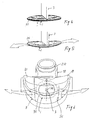
- Figures 4 and 5 show the principle of the present invention. Due to reasons that will be evident below, while the principle is illustrated with reference to a valve having not-circular shutter disk, but with an elongate disk, the principle according to the invention allows to obtain the advantages described before even with traditional circular shutter disks.
- a diametral transversal rib 3 is provided in contact with the outside surface of the shutter disk 1.
- the contact position is such that the rib touches or laps the outside surface of the shutter disk 1 without determining a pressure thereon in closing position of the membrane valve.
- the stop rib 3 may have any thickness at the edge 103 in contact with the shutter disk 1. Such contact edge 103 may be tapered and it has a rounded tip such that it does not engrave or damage the shutter disk 1.
- a variation of the contact surface length between the rib 3 and the shutter disk causes a modification in the opening behaviour of the valve with reference to a overpressure operating in the opening direction thereof on the shutter disk 1.
- the stop rib 3 on one hand avoids or limits in a drastic way the partial swelling deformation of the shutter disk when occurs an opening overpressure, on the other hand it causes an opening behaviour of the valve according to which the shutter disk lifts as if the two portions thereof defined by the area in contact with the stop rib 3 are hinged one with respect to the other. Such opening behaviour is shown in figure 3 .
- the substantially book-like opening thereof causes an increase of the passage section, because at the two areas of the shutter disk opposite to each side of the stop rib 3 the lifting of the shutter disk 1 and/or the sealing lip 101 from the corresponding portion of the valve seat is greater than the case of prior art shutter disks, so that the light or passage section is greater.
- the shutter disk 1 may have a shape different from the circular shape provided in prior art and particularly an elongate shape in the transversal direction of the stop rib 3, on one or both sides of said stop rib 3.
- the plant shape of the shutter disk may be of any type and as already described before said shape may be completely asymmetrical with relation to the axis defined by the pin 201 for clamping the shutter disk 1 to the valve seat.
- the plant shape of the shutter disk 1 is symmetrical at least with reference to the stop rib 3 or it is rotational symmetrical with reference to the axis of the clamping pin 201.
- the elliptic, oval shapes or elongate shapes having semicircular head segments joined by straight or arched perimeter lines are preferred.
- the stop rib 3 is oriented according to the minor axis and perpendicular to the major axis and as well as it is coincident with the axis of the central clamping pin 201.
- valve seat is fabricated with a shape corresponding to that of the shutter disk.
- the shutter disk shape may be asymmetrical with respect to the stop rib 3, said rib may be provided to be coincident with the axis of a clamping pin 201 or in a position laterally offset with respect to this one.
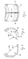
- Figs. 12A and 12B show a perspective view and a plant one of a valve according to a first variation of the invention.
- the stop rib 3 adheres against the shutter disk 1 in a discontinuous way, said rib being toothed manufactured at least at the end in contact with the shutter disk.
- the stop rib 3 branches at the area between the clamping pin 201 and the shutter disk 1 surrounding it and having two branches 503, 603 extending at first in diverging directions and then in converging directions one with respect to the other and joining again in a single branch of the rib comprising therebetween the base for coupling the clamping pin 201 to the shutter disk.
- the arrangement is polygonal, however it may be even curvilinear.
- Figs. 15A and 15B show a further variation of the embodiment according to figs. 12A and 12B wherein the stop rib with toothed contact end is replaced by a row of rod-shaped members spaced one with respect to the other.
- the number of said components may be varied depending on the desired behaviour of the valve and/or material therefrom the shutter disk is made of.
- Figs. 14A and 14B and figs. 17A and 17B show two embodiments of the same variation consisting in providing two stop ribs 3 or two rows of retaining rods 33.
- the two stop ribs 3 that can be even toothed fabricated analogously to the embodiment of fig. 12 , extend on two sides of a minor median axis coincident with the axis of the clamping pin 201 hence with a perfectly symmetrical arrangement.
- the arrangement may be even asymmetrical with respect to said minor median axis, the two stop ribs 3 or the row of retaining rods 33 being arranged one on a side and the other on the opposite side of said minor median axis, or the two stop ribs 3 or the two retaining rods 33 may be arranged at a predetermined distance one from the other on a single side of said minor median axis.
- the above principle of the present invention may be applied also to known membrane valves having an elongate shape and two clamping pins substantially arranged coincident with the centres of the elongate shape.
- the stop rib or ribs and/or the retaining rod or rods may have several arrangements corresponding to the embodiments described before and illustrated with reference to elongate shutter disks having a single clamping pin.
- stop ribs and/or rows of stop rods 33 may be achieved even by providing on the side of the shutter disk facing the valve seat another row of clamping pins cooperating with as many engaging holes of a traverse of the valve seat that divides the passage opening in at least two portions.
- stop ribs 3 or two rows of stop rods 33 it is possible to provide, alternatively or in combination, two rows of clamping pins of the shutter disk aligned along directions coincident to that provided for stop ribs and/or rows of stop rods.
- An advantageous and particularly simple shape is the one providing that the row of clamping pins includes even the clamping pin 201.
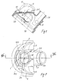
- Figs. 5 to 11 show a particular application of the membrane valve according to the invention.
- said membrane valve is used as outflow valve for the air breathed out by the user in a second reducing stage of an air breathing apparatus for underwater diving.
- the illustrated embodiment provides a membrane valve with symmetric configuration, a single central clamping pin and a stop rib 3 in a position coincident with the minor axis coincident with the clamping pin 201.
- This is not to be intended in limiting sense because it is possible to combine with the second reducing stage a membrane valve according to any of the several variations that have been illustrated and/or described above.
- the example of figs. 5 to 11 provides a second reducing stage with a case 10 delimiting a chamber for supplying air to be breath in or out by the user.
- the air is breathed in by the supply chamber 110 and breathed out therein by means of a mouthpiece (not shown being of a known type per se) of smooth material connected to an intake/expiration mouthpiece 210 communicating with said supply chamber 110.
- valve seat comprising the annular wall 202 sealingly in contact with the sealing peripheral lip 101 of a shutter disk.
- a clamping pin 201 of the shutter disk is engaged by elastic forcing in a hole.
- the valve seat has an elongate or substantially elliptic opening 302 composed of four quadrants spaced-apart by radial ribs 402 for supporting the central hub 102 wherein the central hole engaging the clamping pin 201 of the shutter disk is provided.
- the shutter disk 1 is illustrated by a broken line. Even the rib 3 is illustrated by a broken line.
- the shutter disk has a substantially elliptic shape and cooperates, as already described above, with the surface surrounding the sectors 302 of the passage opening of the valve indicated at 202.
- the shutter disk 1 is applied on the external face of the leveling 310 and such leveling is completely covered on the outside by a C-shaped element 111 composing a transversal outflow duct 11, with reference to the median axis including or parallel to the axis of the clamping pin 201 of the shutter disk 1 or to the axis of the intake/expiration mouthpiece 210 of the case 10.
- the duct 11 has opened head sides and in the central area it is made as it can be opened, the central part 211 thereof being removable like a little cap.
- the removable part 211 of the wall of the outflow duct 11 extends substantially for the all length of the valve in the direction of the axis of the outflow duct 11 so that the removable part can be completely accessible for cleaning purposes.
- a transversal wall constituting in this case the stop rib 3 departed from the central area of said removable part 211.
- the rib 3 adheres against the external face of the shutter disk 1 with its free edge 103, whereby in this case the membrane valve has the same functionalities according to the present invention.
- the removable part 211 of the outflow duct 11 may be secured to the same by means of axial pins with reference to the axis of the outflow duct said pins engaging with corresponding holes 411 of corresponding ears 511 of fixed walls 111 of the outflow duct 11 and removable part 211.
- the fixed parts 111 of the wall of the outflow duct 11 formed the two final ends of the outflow duct 11 and the removable part 211 is interposed therebetween.
- the membrane valve has a better opening behaviour and so it requires a less effort for the user than the effort that is necessary at present with the known membrane outflow valves, but the main part of the outflow flux of breath air is directed towards the outflow orifices of the outflow duct 11 and hence it has a direction that helps the air outflow from the regulator in a laterally offset position with respect to the user field of view.
- valve according to the invention may be employed in all fields wherein the known membrane valves are already used.
- the embodiment of the described second stage is not intended to be considered limitative, the invention extends even to other embodiments that obtain the same advantages by using the same principle.
Landscapes
- Engineering & Computer Science (AREA)
- General Engineering & Computer Science (AREA)
- Mechanical Engineering (AREA)
- Check Valves (AREA)
- Lift Valve (AREA)
- Safety Valves (AREA)
Applications Claiming Priority (2)
| Application Number | Priority Date | Filing Date | Title |
|---|---|---|---|
| ITSV20030003 ITSV20030003A1 (it) | 2003-02-04 | 2003-02-04 | Valvola a membrana e secondo stadio di riduzione di pressione |
| EP20030104276 EP1445521B1 (fr) | 2003-02-04 | 2003-11-19 | Soupape à membrane et régulateur à deuxième étage pour un appareil de respiration à deux étages destiné à une utilisation sous-marine et pourvu d'une telle soupape |
Related Parent Applications (2)
| Application Number | Title | Priority Date | Filing Date |
|---|---|---|---|
| EP20030104276 Division EP1445521B1 (fr) | 2003-02-04 | 2003-11-19 | Soupape à membrane et régulateur à deuxième étage pour un appareil de respiration à deux étages destiné à une utilisation sous-marine et pourvu d'une telle soupape |
| EP03104276.5 Division | 2003-11-19 |
Publications (2)
| Publication Number | Publication Date |
|---|---|
| EP2068054A2 true EP2068054A2 (fr) | 2009-06-10 |
| EP2068054A3 EP2068054A3 (fr) | 2012-11-28 |
Family
ID=32652475
Family Applications (2)
| Application Number | Title | Priority Date | Filing Date |
|---|---|---|---|
| EP20030104276 Expired - Lifetime EP1445521B1 (fr) | 2003-02-04 | 2003-11-19 | Soupape à membrane et régulateur à deuxième étage pour un appareil de respiration à deux étages destiné à une utilisation sous-marine et pourvu d'une telle soupape |
| EP20090151503 Withdrawn EP2068054A3 (fr) | 2003-02-04 | 2003-11-19 | Soupape à membrane et deuxième étage de réduction de la pression pour régulateurs à deux étages pour une utilisation sous-marine de ladite soupape |
Family Applications Before (1)
| Application Number | Title | Priority Date | Filing Date |
|---|---|---|---|
| EP20030104276 Expired - Lifetime EP1445521B1 (fr) | 2003-02-04 | 2003-11-19 | Soupape à membrane et régulateur à deuxième étage pour un appareil de respiration à deux étages destiné à une utilisation sous-marine et pourvu d'une telle soupape |
Country Status (4)
| Country | Link |
|---|---|
| US (1) | US7252110B2 (fr) |
| EP (2) | EP1445521B1 (fr) |
| DE (1) | DE60333723D1 (fr) |
| IT (1) | ITSV20030003A1 (fr) |
Families Citing this family (16)
| Publication number | Priority date | Publication date | Assignee | Title |
|---|---|---|---|---|
| USD747463S1 (en) | 2007-07-30 | 2016-01-12 | Passy-Muir, Inc. | Tracheostomy valve |
| US8051856B2 (en) | 2007-07-30 | 2011-11-08 | Passy-Muir, Inc. | Tracheostomy valves and related methods |
| DE102011113716B4 (de) * | 2011-09-17 | 2016-08-11 | Dräger Safety AG & Co. KGaA | Richtungsventil und Atemschutzmaske mit einem Richtungsventil |
| DE112013001029B4 (de) * | 2012-05-17 | 2018-05-09 | Illinois Tool Works Inc. | Kraftstoffdüsen-Aufnahmeanordnung |
| DE102012018277B4 (de) * | 2012-09-14 | 2020-08-06 | Dräger Safety AG & Co. KGaA | Richtungsventil und Atemschutzprodukt mit einem Richtungsventil |
| US20150087911A1 (en) | 2013-09-26 | 2015-03-26 | Gyrus Acmi, Inc. D.B.A Olympus Surgical Technologies America | Endoscope sheath deflection devices |
| CA2930536A1 (fr) | 2013-11-15 | 2015-05-21 | 3M Innovative Properties Company | Respirateur ayant une soupape d'expiration non-circulaire montee au centre |
| GB2523558A (en) * | 2014-02-26 | 2015-09-02 | Draeger Safety Uk Ltd | Assembly |
| US11554471B2 (en) * | 2014-08-28 | 2023-01-17 | Power Tech Staple and Nail, Inc. | Elastomeric exhaust reed valve for combustion driven fastener hand tool |
| US9345386B1 (en) | 2014-11-24 | 2016-05-24 | Gyrus Acmi, Inc. | Adjustable endoscope sheath |
| US9585547B2 (en) | 2014-11-24 | 2017-03-07 | Gyrus Acmi, Inc. | Adjustable endoscope sheath |
| US9782525B2 (en) | 2015-01-08 | 2017-10-10 | Gyrus Acmi, Inc. | Multi-way valve for a medical instrument |
| DE102016206775A1 (de) * | 2016-04-21 | 2017-10-26 | Uvex Arbeitsschutz Gmbh | Atemschutzmaske |
| US11035491B2 (en) * | 2017-07-03 | 2021-06-15 | Continental Automotive Systems, Inc. | Fuel pump solenoid having hydraulic damping |
| IT201800001827A1 (it) | 2018-01-25 | 2019-07-25 | Mares Spa | Valvola a membrana ed un metodo per la sua realizzazione |
| US20190323625A1 (en) | 2018-04-23 | 2019-10-24 | Rain Bird Corporation | Valve With Reinforcement Ports And Manually Removable Scrubber |
Family Cites Families (11)
| Publication number | Priority date | Publication date | Assignee | Title |
|---|---|---|---|---|
| US1867478A (en) | 1927-08-12 | 1932-07-12 | Firm Dragerwerk Heinr & Bernh | Nonreturn valve for breathing appliances |
| US2225395A (en) * | 1940-06-26 | 1940-12-17 | Acushnett Process Company | Exhalation valve for gas masks |
| US2291603A (en) * | 1940-07-19 | 1942-08-04 | Maurice E Barker | Outlet valve for gas masks |
| US2326651A (en) * | 1941-09-20 | 1943-08-10 | Standard Products Co | Exhalation valve structure for protective masks |
| US2693180A (en) * | 1951-05-03 | 1954-11-02 | Galeazzi Roberto | Exhalation valve for diving suits |
| GB1351384A (en) * | 1971-02-12 | 1974-04-24 | Hawker Siddeley Aviation Ltd | Non-return valves |
| US4219017A (en) * | 1978-11-09 | 1980-08-26 | Burr John D | Pilot regulator |
| US4414973A (en) * | 1981-03-10 | 1983-11-15 | U.S.D. Corp. | Respirator face mask |
| US4729401A (en) * | 1987-01-29 | 1988-03-08 | Burron Medical Inc. | Aspiration assembly having dual co-axial check valves |
| US4838262A (en) * | 1988-05-02 | 1989-06-13 | Mine Safety Appliances Company | Exhalation valve |
| US6412514B1 (en) | 1999-10-26 | 2002-07-02 | Red Valve Company, Inc. | Flip check valve |
-
2003
- 2003-02-04 IT ITSV20030003 patent/ITSV20030003A1/it unknown
- 2003-11-19 DE DE60333723T patent/DE60333723D1/de not_active Expired - Lifetime
- 2003-11-19 EP EP20030104276 patent/EP1445521B1/fr not_active Expired - Lifetime
- 2003-11-19 EP EP20090151503 patent/EP2068054A3/fr not_active Withdrawn
-
2004
- 2004-02-02 US US10/770,090 patent/US7252110B2/en not_active Expired - Lifetime
Non-Patent Citations (1)
| Title |
|---|
| None * |
Also Published As
| Publication number | Publication date |
|---|---|
| EP1445521B1 (fr) | 2010-08-11 |
| EP2068054A3 (fr) | 2012-11-28 |
| ITSV20030003A1 (it) | 2004-08-05 |
| EP1445521A1 (fr) | 2004-08-11 |
| US7252110B2 (en) | 2007-08-07 |
| DE60333723D1 (de) | 2010-09-23 |
| US20040182446A1 (en) | 2004-09-23 |
Similar Documents
| Publication | Publication Date | Title |
|---|---|---|
| EP2068054A2 (fr) | Soupape à membrane et deuxième étage de réduction de la pression pour régulateurs à deux étages pour une utilisation sous-marine de ladite soupape | |
| US10220179B2 (en) | Flow regulation vent | |
| USRE37974E1 (en) | Uni-directional fluid valve | |
| US3990439A (en) | Protective breathing apparatus and valve therefor | |
| US4934362A (en) | Unidirectional fluid valve | |
| US5059208A (en) | Adjustable tracheostoma valve | |
| US5329643A (en) | Diving face mask | |
| US8910663B2 (en) | Uni-directional valve, filtering face mask | |
| US4021863A (en) | Heart valve prosthesis | |
| USRE43289E1 (en) | Uni-directional fluid valve | |
| EP0252890A1 (fr) | Dispositif à soupape | |
| EP1647310A1 (fr) | Masque respiratoire avec valve d'expiration | |
| US4886093A (en) | Vent valve of an air pump | |
| TWI827713B (zh) | 氣管切開術閥 | |
| CN106061436A (zh) | 具有包括活塞形封闭部件的盖部件的发音阀 | |
| CN109069886A (zh) | 呼吸面罩 | |
| EP1663367B1 (fr) | Soupape a pression positive en fin d'expiration | |
| KR20200000868A (ko) | 안면 웨어러블 디바이스의 부착 장치 | |
| KR20230149534A (ko) | 위생 마스크용 지지패드 | |
| CA2404509C (fr) | Clapet d'expiration | |
| GB2304176A (en) | Uni-directional fluid valve | |
| JPH09193891A (ja) | 半開放式呼吸装置の呼吸袋 |
Legal Events
| Date | Code | Title | Description |
|---|---|---|---|
| PUAI | Public reference made under article 153(3) epc to a published international application that has entered the european phase |
Free format text: ORIGINAL CODE: 0009012 |
|
| AC | Divisional application: reference to earlier application |
Ref document number: 1445521 Country of ref document: EP Kind code of ref document: P |
|
| AK | Designated contracting states |
Kind code of ref document: A2 Designated state(s): DE FR IT |
|
| PUAL | Search report despatched |
Free format text: ORIGINAL CODE: 0009013 |
|
| AK | Designated contracting states |
Kind code of ref document: A3 Designated state(s): DE FR IT |
|
| RIC1 | Information provided on ipc code assigned before grant |
Ipc: F16K 15/14 20060101AFI20121023BHEP |
|
| 17P | Request for examination filed |
Effective date: 20130221 |
|
| AKX | Designation fees paid |
Designated state(s): DE FR IT |
|
| 17Q | First examination report despatched |
Effective date: 20130716 |
|
| STAA | Information on the status of an ep patent application or granted ep patent |
Free format text: STATUS: THE APPLICATION IS DEEMED TO BE WITHDRAWN |
|
| 18D | Application deemed to be withdrawn |
Effective date: 20180731 |