EP2068065B1 - Couplages de tuyaux - Google Patents
Couplages de tuyaux Download PDFInfo
- Publication number
- EP2068065B1 EP2068065B1 EP08253347.2A EP08253347A EP2068065B1 EP 2068065 B1 EP2068065 B1 EP 2068065B1 EP 08253347 A EP08253347 A EP 08253347A EP 2068065 B1 EP2068065 B1 EP 2068065B1
- Authority
- EP
- European Patent Office
- Prior art keywords
- stem
- cap
- tube
- head
- locking ring
- Prior art date
- Legal status (The legal status is an assumption and is not a legal conclusion. Google has not performed a legal analysis and makes no representation as to the accuracy of the status listed.)
- Not-in-force
Links
- 230000008878 coupling Effects 0.000 title claims description 46
- 238000010168 coupling process Methods 0.000 title claims description 46
- 238000005859 coupling reaction Methods 0.000 title claims description 46
- 244000273618 Sphenoclea zeylanica Species 0.000 claims description 3
- 238000007789 sealing Methods 0.000 claims description 3
- 239000004033 plastic Substances 0.000 claims description 2
- 229920003023 plastic Polymers 0.000 claims description 2
- 239000002991 molded plastic Substances 0.000 description 5
- 239000002184 metal Substances 0.000 description 4
- 238000003780 insertion Methods 0.000 description 3
- 230000037431 insertion Effects 0.000 description 3
- 239000012530 fluid Substances 0.000 description 2
- 239000007789 gas Substances 0.000 description 2
- 239000007788 liquid Substances 0.000 description 2
- 229910001220 stainless steel Inorganic materials 0.000 description 2
- 239000010935 stainless steel Substances 0.000 description 2
- 229910000831 Steel Inorganic materials 0.000 description 1
- 235000013361 beverage Nutrition 0.000 description 1
- 239000000446 fuel Substances 0.000 description 1
- 239000000463 material Substances 0.000 description 1
- 239000010959 steel Substances 0.000 description 1
- XLYOFNOQVPJJNP-UHFFFAOYSA-N water Substances O XLYOFNOQVPJJNP-UHFFFAOYSA-N 0.000 description 1
Images

Classifications
-
- F—MECHANICAL ENGINEERING; LIGHTING; HEATING; WEAPONS; BLASTING
- F16—ENGINEERING ELEMENTS AND UNITS; GENERAL MEASURES FOR PRODUCING AND MAINTAINING EFFECTIVE FUNCTIONING OF MACHINES OR INSTALLATIONS; THERMAL INSULATION IN GENERAL
- F16L—PIPES; JOINTS OR FITTINGS FOR PIPES; SUPPORTS FOR PIPES, CABLES OR PROTECTIVE TUBING; MEANS FOR THERMAL INSULATION IN GENERAL
- F16L37/00—Couplings of the quick-acting type
- F16L37/08—Couplings of the quick-acting type in which the connection between abutting or axially overlapping ends is maintained by locking members
- F16L37/084—Couplings of the quick-acting type in which the connection between abutting or axially overlapping ends is maintained by locking members combined with automatic locking
- F16L37/091—Couplings of the quick-acting type in which the connection between abutting or axially overlapping ends is maintained by locking members combined with automatic locking by means of a ring provided with teeth or fingers
-
- F—MECHANICAL ENGINEERING; LIGHTING; HEATING; WEAPONS; BLASTING
- F16—ENGINEERING ELEMENTS AND UNITS; GENERAL MEASURES FOR PRODUCING AND MAINTAINING EFFECTIVE FUNCTIONING OF MACHINES OR INSTALLATIONS; THERMAL INSULATION IN GENERAL
- F16L—PIPES; JOINTS OR FITTINGS FOR PIPES; SUPPORTS FOR PIPES, CABLES OR PROTECTIVE TUBING; MEANS FOR THERMAL INSULATION IN GENERAL
- F16L37/00—Couplings of the quick-acting type
- F16L37/08—Couplings of the quick-acting type in which the connection between abutting or axially overlapping ends is maintained by locking members
- F16L37/084—Couplings of the quick-acting type in which the connection between abutting or axially overlapping ends is maintained by locking members combined with automatic locking
- F16L37/092—Couplings of the quick-acting type in which the connection between abutting or axially overlapping ends is maintained by locking members combined with automatic locking by means of elements wedged between the pipe and the frusto-conical surface of the body of the connector
- F16L37/0925—Couplings of the quick-acting type in which the connection between abutting or axially overlapping ends is maintained by locking members combined with automatic locking by means of elements wedged between the pipe and the frusto-conical surface of the body of the connector with rings which bite into the wall of the pipe
-
- F—MECHANICAL ENGINEERING; LIGHTING; HEATING; WEAPONS; BLASTING
- F16—ENGINEERING ELEMENTS AND UNITS; GENERAL MEASURES FOR PRODUCING AND MAINTAINING EFFECTIVE FUNCTIONING OF MACHINES OR INSTALLATIONS; THERMAL INSULATION IN GENERAL
- F16L—PIPES; JOINTS OR FITTINGS FOR PIPES; SUPPORTS FOR PIPES, CABLES OR PROTECTIVE TUBING; MEANS FOR THERMAL INSULATION IN GENERAL
- F16L37/00—Couplings of the quick-acting type
- F16L37/08—Couplings of the quick-acting type in which the connection between abutting or axially overlapping ends is maintained by locking members
- F16L37/084—Couplings of the quick-acting type in which the connection between abutting or axially overlapping ends is maintained by locking members combined with automatic locking
- F16L37/092—Couplings of the quick-acting type in which the connection between abutting or axially overlapping ends is maintained by locking members combined with automatic locking by means of elements wedged between the pipe and the frusto-conical surface of the body of the connector
- F16L37/0926—Couplings of the quick-acting type in which the connection between abutting or axially overlapping ends is maintained by locking members combined with automatic locking by means of elements wedged between the pipe and the frusto-conical surface of the body of the connector with an inner support sleeve arranged within the pipe
-
- F—MECHANICAL ENGINEERING; LIGHTING; HEATING; WEAPONS; BLASTING
- F16—ENGINEERING ELEMENTS AND UNITS; GENERAL MEASURES FOR PRODUCING AND MAINTAINING EFFECTIVE FUNCTIONING OF MACHINES OR INSTALLATIONS; THERMAL INSULATION IN GENERAL
- F16L—PIPES; JOINTS OR FITTINGS FOR PIPES; SUPPORTS FOR PIPES, CABLES OR PROTECTIVE TUBING; MEANS FOR THERMAL INSULATION IN GENERAL
- F16L37/00—Couplings of the quick-acting type
- F16L37/08—Couplings of the quick-acting type in which the connection between abutting or axially overlapping ends is maintained by locking members
- F16L37/084—Couplings of the quick-acting type in which the connection between abutting or axially overlapping ends is maintained by locking members combined with automatic locking
- F16L37/092—Couplings of the quick-acting type in which the connection between abutting or axially overlapping ends is maintained by locking members combined with automatic locking by means of elements wedged between the pipe and the frusto-conical surface of the body of the connector
- F16L37/0927—Couplings of the quick-acting type in which the connection between abutting or axially overlapping ends is maintained by locking members combined with automatic locking by means of elements wedged between the pipe and the frusto-conical surface of the body of the connector the wedge element being axially displaceable for releasing the coupling
Definitions
- This invention relates to tube couplings for connecting flexible tubes or conduits for carrying gases, liquids or cables together.
- EP 1703191 and US 2005/0035597 disclose a tube coupling for receiving and holding an end of a tube comprising a coupling body having a head and a hollow stem and projecting from the head and adapted to engage in a tube to be secured to the coupling body, a cap mounted on the coupling body and encircling the stem with a gap between the cap and stem to receive a tube engaged over the stem, a tube locking device in the cap for locking the tube against withdrawal from the stem and a locking ring located on the stem within the cap, the ring having both inwardly and outwardly projecting teeth for engaging respectively the inner and outer surfaces of the cap and stem to lock the cap on the stem.
- such a coupling is characterised in that the locking ring is moulded in plastics and embodies a grab ring having both inwardly and outwardly projecting teeth to engage the inner surface of the cap and the outer surface of the stem respectively; the ring having cylindrical inner and outer surfaces and the outwardly projecting teeth of the grab ring project beyond the outer surface to engage in the cap and the inwardly projecting teeth project beyond the inner surface to engage the stem, the ring being recessed adjacent the sides of the outwardly projecting teeth facing the head of the coupling body to allow the outwardly projecting teeth to flex towards the head of the coupling body as the cap is pressed over the ring so that the outwardly projecting teeth press against the inner surface of the cap to grip the cap; and the ring being recessed adjacent the sides of the inwardly projecting teeth facing away from the head of the coupling body to allow the inwardly projecting teeth to flex away from the head as the ring is located on the stem so that the inwardly projecting teeth press against
- the stem has an enlarged diameter portion adjacent the head to receive the locking ring.
- the stem may have encircling recess adjacent a distal end remote from the coupling body to receive an O-ring seal for sealing with the inner surface of the tube inserted over the stem.
- the cap may have an internal taper towards the open end of the cap remote from the head and the tube locking device comprises a collet having a head with axially extending collet teeth projecting into the cap, the collet teeth engaging between the tapered surface on the inside of the cap and the tube to lock the tube to the stem to prevent withdrawal of the tube from the stem.
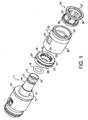
- the drawings show an inline double ended tube coupling body for connecting a pair of tubes together.
- the tubes may be flexible tubes or may be rigid conduit and may be used for an air or gas line or for carrying liquid such as water, beverages or fuels or hydraulic fluids.
- the coupling comprises a shallow circular head 10 having hollow stems 11 formed coaxially with and projecting on either side of the head. Each stem has an enlarged diameter portion 12 for receiving an annular locking ring which will be described later.
- the enlarged portion 12 is connected by a shallow step 13 to a main stem portion 14 for receiving the end of a tube to be coupled to the coupling body.
- the stem terminates in an end face 15 and has a throughway 16 running through the stem, head 10 and stem on the other side of the head for flow of fluid between the tubes connected to the coupling body.
- the main portion 14 of the stem has an annular groove 17 located adjacent the end of the stem to receive an O-ring seal 18 for sealing on the inside surface of a tube to be located on the stem.
- a moulded plastics locking ring 19 is provided for insertion over the stem onto the enlarged portion 12 of the stem adjacent the head 10.
- the locking ring has cylindrical inner and outer faces 20, 21 and a steel grab ring is moulded into the locking ring having one set of radially inwardly projecting teeth 22 for gripping the enlarged portion 12 of the stem and a set of radially outwardly projecting teeth 23 for engaging in a cap to be located over the stem as described later.
- Channel shaped recesses 24 are formed around the inner face 20 of the ring 19 extending between the radial teeth 22 and the side 25 of the ring disposed away from the head 10.
- the channels provide spaces adjacent the teeth into which the teeth can flex as the ring 19 is forced onto the enlarged portion of the stem 12 so that when the ring has been positioned adjacent the head 10, the flexing of the teeth 22 causes the edges of the teeth to engage and grip the surface of the enlarged portion of the stem to resist withdrawal of the ring from the stem.
- the outer face 21 of the ring is formed with four arcuate slots 26 on the side of the teeth 23 adjacent the head 10 to provide space into which the teeth 23 can flex.
- a moulded plastics cap 30 having a main body of cylindrical form is located over the stem 11 of the coupling body and is held in place by the projecting teeth 23 on the outer side of the locking ring 19 which are flexed towards the head 10 as the cap is forced over the locking ring. The resulting flexing of the teeth to press against the inside surface of the cap to resist withdrawal of the cap from the locking ring and stem.
- the cap 30 is of generally uniform wall thickness and has a tapered portion 31 adjacent the end of the cap remote from the head which terminates in cylindrical portion 32 with a flared entry 33.
- a moulded plastics collet indicated generally at 34 is located in the cap, the collet having a head 35 which lies outside the entry 33 to the cap, a short annular part 36 and a plurality of flexible legs 37 extending axially from the annular part and terminating in arcuate heads 38 which have metal teeth 39 moulded into the heads and projecting on the inner sides of the heads to engage the outer surface of a tube inserted through the collet cap and onto the stem 14.
- the collet 34 can be seen located in the open end of the cap with the heads 38 on the arms 37 of the collet engageable with the inside face of the tapered section 31 of the cap so that as the collet is drawn out of the cap, the teeth are pressed inwardly to engage the outer surface of a tube extending through the collet.
- a tube to be locked in the coupling body is shown at 40 and is located in line with the passage into the coupling body ready for insertion.
- the enlarged area designated detail A is shown in figure 3 where the locking ring 19 can be seen located on the enlarged portion 12 of the stem with the teeth 22 projecting on the inner side of the locking ring 19 engaging the surface of the stem to resist withdrawal of the locking ring from the stem and the teeth 23 on the outer side of the locking ring engaging on the inner surface of the cap 30 to prevent cap from being withdrawn.
- the cap 30 is formed with a pair of diametrically opposed rectangular windows 41 for viewing inside the assembly to enable the operator to be sure that a tube has been fully inserted onto the stem 14 and is held in place by the collet 34.
- the coupling body and stem form a single moulded plastics unit as does the locking ring 19, the cap 30 and the collet 34 with the grab ring in the locking ring 19 being formed from stainless steel and the teeth incorporated in the heads of the collet also being formed from stainless steel.
- the coupling body could be formed in metal and in the case where the connector is to have a connection on one side as described above and a threaded connection on the other side, metal would be the preferred material.
- the cap may, as indicated above, be formed from moulded plastics or may be formed from metal.
- the collet form locking device for locking a tube in the cap may be replaced by a number of other forms of locking device such as a grab ring.
- the inwardly and outwardly projecting teeth on the locking ring 19 are formed to extend radially outwardly and radially inwardly as manufactured.
- the teeth can be pre-bent in the appropriate directions for locking the cap to the outer side of the locking ring and locking the inner side of the ring onto the stem.
- the cap, locking ring and collet can be supplied as a unit or cartridge for location on the stem of a coupling body or unit provided by a customer.
- the tube coupling provides a flexible and simple arrangement for connecting tubes together. It will be noted that the coupling body has a diameter only a little in excess of the diameter of the tube to be coupled to the coupling body and the arrangement provides a clean and simple design appearance.
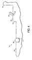
- FIG. 4 of the drawings shows a modified form of stem 11 for the coupling in which an annular groove 42 is formed in the enlarged portion 12 of the stem adjacent head 10 in which the inwardly projecting teeth 22 of locking ring 19 can engage when the ring is located over the stem.
- the arrangement prevents the ring from "unwinding" with rotation from the stem.
Landscapes
- Engineering & Computer Science (AREA)
- General Engineering & Computer Science (AREA)
- Mechanical Engineering (AREA)
- Quick-Acting Or Multi-Walled Pipe Joints (AREA)
- Separation Using Semi-Permeable Membranes (AREA)
Claims (5)
- Raccord de tube permettant de recevoir et de maintenir une extrémité d'un tube (40) comprenant un corps de raccord ayant une tête (10) et une tige creuse (11) faisant saillie à partir de la tête (10) et adaptée pour s'engager dans un tube à fixer au corps de raccord, un capuchon (30) monté sur le corps de raccord et entourant la tige (11) avec un espace entre le capuchon (30) et la tige (11) pour recevoir un tube (40) engagé sur la tige (11), un dispositif de verrouillage de tube (34) dans le capuchon (30) pour verrouiller le tube (40) à l'encontre d'un retrait à partir de la tige (11) et une bague de verrouillage (19) située sur la tige (11) à l'intérieur du capuchon (30), la bague de verrouillage (19) ayant des dents faisant saillie à la fois vers l'intérieur (22) et vers l'extérieur (23) pour s'engager respectivement avec les surfaces interne et externe du capuchon (30) et de la tige (11) pour verrouiller le capuchon (30) sur la tige (11),
caractérisé en ce que la bague de verrouillage (19) est moulée en matières plastiques et incarne une bague de prise ayant des dents faisant saillie à la fois vers l'intérieur (22) et vers l'extérieur (23) pour s'engager avec la surface interne du capuchon (30) et la surface externe de la tige (11) respectivement ; la bague de verrouillage (19) ayant des surfaces cylindriques interne et externe et les dents faisant saillie vers l'extérieur (23) de la bague de prise font saillie au-delà de la surface externe pour s'engager dans le capuchon (30) et les dents faisant saillie vers l'intérieur (22) font saillie au-delà de la surface interne pour s'engager avec la tige (11), la bague de verrouillage (19) étant évidée à proximité des côtés des dents faisant saillie vers l'extérieur (23) faisant face à la tête (10) du corps de raccord pour permettre aux dents faisant saillie vers l'extérieur (23) de se fléchir vers la tête (10) du corps de raccord à mesure que le capuchon (30) est pressé sur la bague de verrouillage (19) de sorte que les dents faisant saillie vers l'extérieur (23) se pressent contre la surface interne du capuchon (30) pour saisir le capuchon (30) ; et la bague de verrouillage (19) étant évidée à proximité des côtés des dents faisant saillie vers l'intérieur (22) opposées à la tête (30) du corps de raccord pour permettre aux dents faisant saillie vers l'intérieur (22) de se fléchir en s'écartant de la tête (10) à mesure que la bague de verrouillage (19) est située sur la tige (11) de sorte que les dents faisant saillie vers l'intérieur (22) se pressent contre la surface externe de la tige (11) pour saisir la tige (11). - Raccord de tube tel que revendiqué dans la revendication 1, dans lequel la tige (11) a une partie de diamètre élargie (12) à proximité de la tête (10) du corps de raccord pour recevoir la bague de verrouillage (19).
- Raccord de tube tel que revendiqué dans la revendication 1 ou 2, dans lequel la tige (11) a un évidement périphérique (17) à proximité d'une extrémité distale à distance du corps de raccord pour recevoir un joint d'étanchéité torique (18) afin d'assurer l'étanchéité avec la surface interne du tube (40) inséré sur la tige (11).
- Raccord de tube tel que revendiqué dans l'une des revendications précédentes, dans lequel le capuchon (30) a un cône interne vers une extrémité ouverte du capuchon (30) à distance de la tête (10) et le dispositif de verrouillage de tube (34) comprend une douille (34) ayant une tête (38) avec des dents de douille s'étendant axialement faisant saillie dans le capuchon (30), les dents de douille s'engageant entre la surface conique située à l'intérieur du capuchon (30) et le tube (40) pour verrouiller le tube (40) sur la tige (11) afin d'empêcher un retrait du tube (40) à partir de la tige (11).
- Raccord de tube tel que revendiqué dans l'une des revendications précédentes, dans lequel la tige (11) a une rainure périphérique annulaire (42) sur laquelle les dents faisant saillie vers l'intérieur sur la bague de verrouillage (19) s'engagent pour maintenir la bague de verrouillage (19) sur la tige (11).
Applications Claiming Priority (1)
| Application Number | Priority Date | Filing Date | Title |
|---|---|---|---|
| GBGB0723646.6A GB0723646D0 (en) | 2007-12-03 | 2007-12-03 | Tube couplings |
Publications (3)
| Publication Number | Publication Date |
|---|---|
| EP2068065A2 EP2068065A2 (fr) | 2009-06-10 |
| EP2068065A3 EP2068065A3 (fr) | 2013-12-25 |
| EP2068065B1 true EP2068065B1 (fr) | 2015-06-17 |
Family
ID=38982904
Family Applications (1)
| Application Number | Title | Priority Date | Filing Date |
|---|---|---|---|
| EP08253347.2A Not-in-force EP2068065B1 (fr) | 2007-12-03 | 2008-10-16 | Couplages de tuyaux |
Country Status (7)
| Country | Link |
|---|---|
| US (1) | US7758085B2 (fr) |
| EP (1) | EP2068065B1 (fr) |
| KR (1) | KR101111670B1 (fr) |
| AU (1) | AU2008237587B2 (fr) |
| ES (1) | ES2541550T3 (fr) |
| GB (1) | GB0723646D0 (fr) |
| NZ (1) | NZ572174A (fr) |
Families Citing this family (14)
| Publication number | Priority date | Publication date | Assignee | Title |
|---|---|---|---|---|
| GB0809685D0 (en) * | 2008-05-28 | 2008-07-02 | Guest John Int Ltd | Improvements in or relating to tube couplings |
| GB201010501D0 (en) | 2010-06-22 | 2010-08-04 | Guest John Int Ltd | A tube coupling |
| US8925344B2 (en) | 2010-09-08 | 2015-01-06 | General Electric Company | Fitting assemblies to provide fluid supply to ice and water dispensers in refrigerator doors |
| GB201205575D0 (en) | 2012-03-29 | 2012-05-16 | Guest John Int Ltd | Improvements in or relating to tube couplings |
| US9490619B2 (en) * | 2012-10-25 | 2016-11-08 | Bridgeport Fittings, Inc. | Push-on liquidtight conduit fitting |
| GB201317952D0 (en) | 2013-10-10 | 2013-11-27 | Guest John Int Ltd | A connector for connecting to a tube |
| GB201317990D0 (en) | 2013-10-11 | 2013-11-27 | Guest John Int Ltd | A conncetor |
| US10161551B2 (en) | 2015-07-09 | 2018-12-25 | A. Raymond Et Cie | Quick-connector |
| KR200485748Y1 (ko) * | 2015-10-05 | 2018-02-19 | 손병천 | 양측으로 압축되어 고정되는 파이프 크랩링 |
| US10533688B2 (en) * | 2016-05-16 | 2020-01-14 | Victaulic Company | Coupling having tabbed retainer |
| CN106151735B (zh) * | 2016-08-01 | 2018-01-09 | 浙江工业大学 | 一种管路快速接头 |
| USD1060429S1 (en) * | 2020-05-30 | 2025-02-04 | Fairview Ltd. | Gas manifold |
| US11701303B1 (en) * | 2020-08-17 | 2023-07-18 | Wealth Acquisition Group LLC | Quick release connection for enteral feeding tube |
| US12442475B2 (en) * | 2025-03-13 | 2025-10-14 | Xiamen Tongjie Technology., Ltd | Push type conduit joint release structure |
Family Cites Families (53)
| Publication number | Priority date | Publication date | Assignee | Title |
|---|---|---|---|---|
| GB1520742A (en) * | 1975-07-30 | 1978-08-09 | Guest J D | Couplings for tubes |
| GB2132296B (en) * | 1982-12-13 | 1986-02-05 | Guest John Ltd | Tube coupling |
| GB2132295B (en) * | 1982-12-13 | 1986-03-19 | Guest John Ltd | Pipe coupling |
| GB2143603B (en) * | 1983-07-21 | 1986-07-09 | Guest John Ltd | Quick release tube coupling |
| US4722560A (en) * | 1983-07-21 | 1988-02-02 | Guest John D | Quick release tube coupling |
| US4637636A (en) * | 1984-11-12 | 1987-01-20 | Guest John D | Tube couplings |
| GB2172356B (en) * | 1985-03-12 | 1989-07-19 | Guest John D | Improvements in or relating to tube couplings |
| GB2172948B (en) | 1985-03-28 | 1988-07-06 | Guest John D | Improvements in or relating to tube couplers |
| US4654246A (en) * | 1985-09-05 | 1987-03-31 | Actief, N.V. | Self-engaging separable fastener |
| AU594180B2 (en) * | 1986-07-30 | 1990-03-01 | John Derek Guest | Tube couplings |
| EP0333948A1 (fr) * | 1988-03-25 | 1989-09-27 | John Guest Limited | Raccord de tuyaux |
| DE3866869D1 (de) * | 1988-03-25 | 1992-01-23 | Guest John D | Rohrkupplung. |
| EP0333949B1 (fr) * | 1988-03-25 | 1991-12-11 | John Derek Guest | Raccord de tuyaux |
| GB2261042A (en) * | 1991-11-01 | 1993-05-05 | Guest John D | Improvements in or relating to tube couplings for co-axial tubing |
| US5201549A (en) | 1992-01-17 | 1993-04-13 | Senior Engineering Investments, B.V. | Thermal isolation coupling system |
| GB9204375D0 (en) * | 1992-02-28 | 1992-04-08 | Guest John D | Improvements in or relating to tube couplings |
| GB9219041D0 (en) * | 1992-09-09 | 1992-10-21 | Guest John D | Improvments in or relating to collets for tube couplings |
| US5443289A (en) * | 1992-11-11 | 1995-08-22 | Guest; John D. | Tube couplings |
| GB9400585D0 (en) * | 1994-01-13 | 1994-03-09 | Guest John D | Improvements in or relating to tube couplings |
| GB9402758D0 (en) * | 1994-02-11 | 1994-04-06 | Guest John D | Improvements in or relating to tube couplings |
| FR2717883B1 (fr) * | 1994-03-04 | 1996-06-14 | Hutchinson | Dispositif de raccordement rapide et étanche pour conduites tubulaires. |
| EP0972981A3 (fr) | 1994-09-14 | 2000-04-26 | John Derek Guest | Anneau de retenue |
| GB9419003D0 (en) * | 1994-09-21 | 1994-11-09 | Guest John D | Improvements in or relating to tube coupling collets |
| GB9512974D0 (en) * | 1995-06-26 | 1995-08-30 | Guest John D | Improvements in or relating to tube coupling bodies |
| GB9515497D0 (en) * | 1995-07-28 | 1995-09-27 | Guest John D | Improvements in or relating to tube couplings |
| DE69621292T2 (de) * | 1995-07-28 | 2002-12-19 | John Guest Ltd., West Drayton | Rohrverbindung |
| GB9515473D0 (en) * | 1995-07-28 | 1995-09-27 | Guest John D | Improvements in or relating to tube couplings |
| GB9519199D0 (en) * | 1995-09-20 | 1995-11-22 | Guest John D | Improvements in or relating to tube couplings |
| GB9806642D0 (en) * | 1998-03-27 | 1998-05-27 | Guest John D | Improvements in or relating to tube coupling |
| GB9816537D0 (en) * | 1998-07-29 | 1998-09-30 | Guest John D | Tube coupling devices |
| EP1004807B1 (fr) * | 1998-11-24 | 2002-09-18 | John Guest Limited | Support d'extrémité de tubes pour une boíte de raccordement de tuyaux |
| JP4572283B2 (ja) * | 1999-03-04 | 2010-11-04 | Smc株式会社 | チャック及び管継手 |
| GB0011317D0 (en) * | 2000-05-10 | 2000-06-28 | John Guest International Limit | Tube couplings |
| BR0112088A (pt) * | 2000-06-30 | 2004-02-10 | Itt Mfg Enterprises Inc | Conector de fluido soldado por rotação usando tubo de metal revestido por plástico |
| JP3595766B2 (ja) * | 2000-10-23 | 2004-12-02 | Smc株式会社 | 管継手 |
| US6929289B1 (en) * | 2001-02-15 | 2005-08-16 | John Guest International Ltd. | Tube couplings |
| GB0103774D0 (en) * | 2001-02-15 | 2001-04-04 | Guest John Int Ltd | Improvements in or relating to tube couplings |
| US6467816B1 (en) * | 2001-08-21 | 2002-10-22 | Huang-Fu Huang | Water pipe joint |
| GB0126798D0 (en) * | 2001-11-07 | 2002-01-02 | Guest John Int Ltd | Improvements in or relating to tube couplings |
| PT1446605E (pt) | 2001-11-23 | 2008-12-12 | Georg Fischer Haustechnik Ag | União rápida para tubos |
| GB0209899D0 (en) * | 2002-04-30 | 2002-06-05 | Guest John Int Ltd | Improvements in or relating to tube couplings |
| GB0209897D0 (en) * | 2002-04-30 | 2002-06-05 | Guest John Int Ltd | Improvements in or relating to tube couplings |
| GB0221076D0 (en) * | 2002-09-11 | 2002-10-23 | Guest John Int Ltd | Improvements in or relating to tube couplings |
| GB0224785D0 (en) * | 2002-10-24 | 2002-12-04 | Guest John Int Ltd | Temporary closure devices and tube couplings incorporating such devices |
| JP4264937B2 (ja) * | 2003-07-09 | 2009-05-20 | Smc株式会社 | チャック及び管継手 |
| GB0421808D0 (en) * | 2004-10-01 | 2004-11-03 | Imi Norgren Ltd | Coupling device |
| GB0504899D0 (en) * | 2005-03-09 | 2005-04-13 | Guest John Int Ltd | Improvements in or relating to tube couplings |
| DE202005004522U1 (de) | 2005-03-17 | 2005-06-23 | Tece Gmbh & Co. Kg | Rohrleitungskupplung |
| GB0516532D0 (en) * | 2005-08-11 | 2005-09-21 | Guest John Int Ltd | Improvements in or relating to liquid flow control devices |
| GB0516530D0 (en) * | 2005-08-11 | 2005-09-21 | Guest John Int Ltd | Improvements in or relating to liquid flow control devices |
| GB0602757D0 (en) * | 2006-02-10 | 2006-03-22 | Guest John Int Ltd | Improvements in or relating to tube couplings for connecting a pair of conduits for carrying a cable |
| GB0603429D0 (en) * | 2006-02-21 | 2006-04-05 | Guest John Int Ltd | Improvements in or relating to tube couplings |
| GB0624784D0 (en) * | 2006-12-12 | 2007-01-17 | Guest John Int Ltd | Improvements in or relating to tube couplings |
-
2007
- 2007-12-03 GB GBGB0723646.6A patent/GB0723646D0/en not_active Ceased
-
2008
- 2008-10-16 ES ES08253347.2T patent/ES2541550T3/es active Active
- 2008-10-16 EP EP08253347.2A patent/EP2068065B1/fr not_active Not-in-force
- 2008-10-21 NZ NZ572174A patent/NZ572174A/en not_active IP Right Cessation
- 2008-10-29 AU AU2008237587A patent/AU2008237587B2/en not_active Ceased
- 2008-11-13 US US12/270,450 patent/US7758085B2/en not_active Expired - Fee Related
- 2008-11-25 KR KR1020080117458A patent/KR101111670B1/ko not_active Expired - Fee Related
Also Published As
| Publication number | Publication date |
|---|---|
| ES2541550T3 (es) | 2015-07-21 |
| KR101111670B1 (ko) | 2012-02-17 |
| US7758085B2 (en) | 2010-07-20 |
| AU2008237587A1 (en) | 2009-06-18 |
| GB0723646D0 (en) | 2008-01-16 |
| NZ572174A (en) | 2010-02-26 |
| AU2008237587B2 (en) | 2012-09-27 |
| EP2068065A2 (fr) | 2009-06-10 |
| EP2068065A3 (fr) | 2013-12-25 |
| KR20090057899A (ko) | 2009-06-08 |
| US20090140514A1 (en) | 2009-06-04 |
Similar Documents
| Publication | Publication Date | Title |
|---|---|---|
| EP2068065B1 (fr) | Couplages de tuyaux | |
| JP4511738B2 (ja) | チューブカップリング | |
| US5474336A (en) | Quick connect tube couplings | |
| CN102667293B (zh) | 一种用于启封管道组合件内的管道的设备 | |
| CN102639915A (zh) | 抗旋转抓爪环 | |
| US6692036B2 (en) | Universal interlocking fitting | |
| WO2016014767A1 (fr) | Raccord de tube universel pouvant s'adapter à des tubes de différentes tailles | |
| US20070018450A1 (en) | Fitting assembly for internally sealing a corrugated tube and a method for using the same | |
| US20230003322A1 (en) | Tubular connector | |
| WO2006112726A1 (fr) | Raccord pour tubes pour conduites d'ecoulement | |
| US12338928B2 (en) | Plumbing fitting | |
| US20110169259A1 (en) | Tube fitting connection | |
| CN216666836U (zh) | 一种连接接头和取管装置 | |
| CN219866826U (zh) | 快接组件、冷胆结构和净水机 | |
| US12345359B2 (en) | Tube coupling | |
| US20080061554A1 (en) | Connector Part | |
| CN118856131A (zh) | 快接组件、冷胆结构和净水机 | |
| KR200302183Y1 (ko) | 호스용 연결 구조물 | |
| US12098793B1 (en) | Quick coupling for pipelines | |
| CN211599880U (zh) | 一种带有密封装置的车用尼龙管快插接头 | |
| KR200318940Y1 (ko) | 배관 연결구 | |
| GB2430015A (en) | Branch connector retained by hooked arms | |
| EP4399429A1 (fr) | Raccord tubulaire | |
| GB2360073A (en) | A tube coupling with ultrasonically welded plastics member | |
| WO2014153186A1 (fr) | Appareils et procédés conçus pour assurer des raccordements rapides avec des caractéristiques de retenue |
Legal Events
| Date | Code | Title | Description |
|---|---|---|---|
| PUAI | Public reference made under article 153(3) epc to a published international application that has entered the european phase |
Free format text: ORIGINAL CODE: 0009012 |
|
| AK | Designated contracting states |
Kind code of ref document: A2 Designated state(s): AT BE BG CH CY CZ DE DK EE ES FI FR GB GR HR HU IE IS IT LI LT LU LV MC MT NL NO PL PT RO SE SI SK TR |
|
| AX | Request for extension of the european patent |
Extension state: AL BA MK RS |
|
| PUAL | Search report despatched |
Free format text: ORIGINAL CODE: 0009013 |
|
| AK | Designated contracting states |
Kind code of ref document: A3 Designated state(s): AT BE BG CH CY CZ DE DK EE ES FI FR GB GR HR HU IE IS IT LI LT LU LV MC MT NL NO PL PT RO SE SI SK TR |
|
| AX | Request for extension of the european patent |
Extension state: AL BA MK RS |
|
| RIC1 | Information provided on ipc code assigned before grant |
Ipc: F16L 37/092 20060101ALI20131118BHEP Ipc: F16L 37/091 20060101AFI20131118BHEP |
|
| 17P | Request for examination filed |
Effective date: 20140226 |
|
| RBV | Designated contracting states (corrected) |
Designated state(s): AT BE BG CH CY CZ DE DK EE ES FI FR GB GR HR HU IE IS IT LI LT LU LV MC MT NL NO PL PT RO SE SI SK TR |
|
| GRAP | Despatch of communication of intention to grant a patent |
Free format text: ORIGINAL CODE: EPIDOSNIGR1 |
|
| INTG | Intention to grant announced |
Effective date: 20140725 |
|
| AKX | Designation fees paid |
Designated state(s): DE ES FR GB IT |
|
| GRAJ | Information related to disapproval of communication of intention to grant by the applicant or resumption of examination proceedings by the epo deleted |
Free format text: ORIGINAL CODE: EPIDOSDIGR1 |
|
| GRAP | Despatch of communication of intention to grant a patent |
Free format text: ORIGINAL CODE: EPIDOSNIGR1 |
|
| GRAP | Despatch of communication of intention to grant a patent |
Free format text: ORIGINAL CODE: EPIDOSNIGR1 |
|
| RIN1 | Information on inventor provided before grant (corrected) |
Inventor name: GUEST, TIMOTY STEVEN HEATHFIELD |
|
| INTG | Intention to grant announced |
Effective date: 20141205 |
|
| INTC | Intention to grant announced (deleted) | ||
| RIN1 | Information on inventor provided before grant (corrected) |
Inventor name: GUEST, TIMOTY STEVEN |
|
| INTG | Intention to grant announced |
Effective date: 20141222 |
|
| GRAS | Grant fee paid |
Free format text: ORIGINAL CODE: EPIDOSNIGR3 |
|
| GRAA | (expected) grant |
Free format text: ORIGINAL CODE: 0009210 |
|
| AK | Designated contracting states |
Kind code of ref document: B1 Designated state(s): DE ES FR GB IT |
|
| REG | Reference to a national code |
Ref country code: GB Ref legal event code: FG4D |
|
| REG | Reference to a national code |
Ref country code: ES Ref legal event code: FG2A Ref document number: 2541550 Country of ref document: ES Kind code of ref document: T3 Effective date: 20150721 |
|
| REG | Reference to a national code |
Ref country code: DE Ref legal event code: R096 Ref document number: 602008038586 Country of ref document: DE |
|
| REG | Reference to a national code |
Ref country code: FR Ref legal event code: PLFP Year of fee payment: 8 |
|
| REG | Reference to a national code |
Ref country code: DE Ref legal event code: R097 Ref document number: 602008038586 Country of ref document: DE |
|
| PLBE | No opposition filed within time limit |
Free format text: ORIGINAL CODE: 0009261 |
|
| STAA | Information on the status of an ep patent application or granted ep patent |
Free format text: STATUS: NO OPPOSITION FILED WITHIN TIME LIMIT |
|
| 26N | No opposition filed |
Effective date: 20160318 |
|
| REG | Reference to a national code |
Ref country code: FR Ref legal event code: PLFP Year of fee payment: 9 |
|
| REG | Reference to a national code |
Ref country code: FR Ref legal event code: PLFP Year of fee payment: 10 |
|
| REG | Reference to a national code |
Ref country code: FR Ref legal event code: PLFP Year of fee payment: 11 |
|
| PGFP | Annual fee paid to national office [announced via postgrant information from national office to epo] |
Ref country code: DE Payment date: 20181019 Year of fee payment: 11 |
|
| PGFP | Annual fee paid to national office [announced via postgrant information from national office to epo] |
Ref country code: ES Payment date: 20181102 Year of fee payment: 11 Ref country code: IT Payment date: 20181019 Year of fee payment: 11 Ref country code: GB Payment date: 20181025 Year of fee payment: 11 Ref country code: FR Payment date: 20181022 Year of fee payment: 11 |
|
| REG | Reference to a national code |
Ref country code: DE Ref legal event code: R119 Ref document number: 602008038586 Country of ref document: DE |
|
| PG25 | Lapsed in a contracting state [announced via postgrant information from national office to epo] |
Ref country code: DE Free format text: LAPSE BECAUSE OF NON-PAYMENT OF DUE FEES Effective date: 20200501 |
|
| GBPC | Gb: european patent ceased through non-payment of renewal fee |
Effective date: 20191016 |
|
| PG25 | Lapsed in a contracting state [announced via postgrant information from national office to epo] |
Ref country code: GB Free format text: LAPSE BECAUSE OF NON-PAYMENT OF DUE FEES Effective date: 20191016 Ref country code: IT Free format text: LAPSE BECAUSE OF NON-PAYMENT OF DUE FEES Effective date: 20191016 Ref country code: FR Free format text: LAPSE BECAUSE OF NON-PAYMENT OF DUE FEES Effective date: 20191031 |
|
| REG | Reference to a national code |
Ref country code: ES Ref legal event code: FD2A Effective date: 20210303 |
|
| PG25 | Lapsed in a contracting state [announced via postgrant information from national office to epo] |
Ref country code: ES Free format text: LAPSE BECAUSE OF NON-PAYMENT OF DUE FEES Effective date: 20191017 |