EP2068217B1 - Procédé de contrôle de moteur CC - Google Patents
Procédé de contrôle de moteur CC Download PDFInfo
- Publication number
- EP2068217B1 EP2068217B1 EP08020624A EP08020624A EP2068217B1 EP 2068217 B1 EP2068217 B1 EP 2068217B1 EP 08020624 A EP08020624 A EP 08020624A EP 08020624 A EP08020624 A EP 08020624A EP 2068217 B1 EP2068217 B1 EP 2068217B1
- Authority
- EP
- European Patent Office
- Prior art keywords
- move
- motor
- requested
- rotor
- deceleration
- Prior art date
- Legal status (The legal status is an assumption and is not a legal conclusion. Google has not performed a legal analysis and makes no representation as to the accuracy of the status listed.)
- Not-in-force
Links
Images

Classifications
-
- G—PHYSICS
- G05—CONTROLLING; REGULATING
- G05B—CONTROL OR REGULATING SYSTEMS IN GENERAL; FUNCTIONAL ELEMENTS OF SUCH SYSTEMS; MONITORING OR TESTING ARRANGEMENTS FOR SUCH SYSTEMS OR ELEMENTS
- G05B19/00—Program-control systems
- G05B19/02—Program-control systems electric
- G05B19/18—Numerical control [NC], i.e. automatically operating machines, in particular machine tools, e.g. in a manufacturing environment, so as to execute positioning, movement or co-ordinated operations by means of program data in numerical form
- G05B19/19—Numerical control [NC], i.e. automatically operating machines, in particular machine tools, e.g. in a manufacturing environment, so as to execute positioning, movement or co-ordinated operations by means of program data in numerical form characterised by positioning or contouring control systems, e.g. to control position from one programmed point to another or to control movement along a programmed continuous path
- G05B19/21—Numerical control [NC], i.e. automatically operating machines, in particular machine tools, e.g. in a manufacturing environment, so as to execute positioning, movement or co-ordinated operations by means of program data in numerical form characterised by positioning or contouring control systems, e.g. to control position from one programmed point to another or to control movement along a programmed continuous path using an incremental digital measuring device
- G05B19/23—Numerical control [NC], i.e. automatically operating machines, in particular machine tools, e.g. in a manufacturing environment, so as to execute positioning, movement or co-ordinated operations by means of program data in numerical form characterised by positioning or contouring control systems, e.g. to control position from one programmed point to another or to control movement along a programmed continuous path using an incremental digital measuring device for point-to-point control
- G05B19/231—Numerical control [NC], i.e. automatically operating machines, in particular machine tools, e.g. in a manufacturing environment, so as to execute positioning, movement or co-ordinated operations by means of program data in numerical form characterised by positioning or contouring control systems, e.g. to control position from one programmed point to another or to control movement along a programmed continuous path using an incremental digital measuring device for point-to-point control the positional error is used to control continuously the servomotor according to its magnitude
- G05B19/232—Numerical control [NC], i.e. automatically operating machines, in particular machine tools, e.g. in a manufacturing environment, so as to execute positioning, movement or co-ordinated operations by means of program data in numerical form characterised by positioning or contouring control systems, e.g. to control position from one programmed point to another or to control movement along a programmed continuous path using an incremental digital measuring device for point-to-point control the positional error is used to control continuously the servomotor according to its magnitude with speed feedback only
-
- B—PERFORMING OPERATIONS; TRANSPORTING
- B41—PRINTING; LINING MACHINES; TYPEWRITERS; STAMPS
- B41J—TYPEWRITERS; SELECTIVE PRINTING MECHANISMS, i.e. MECHANISMS PRINTING OTHERWISE THAN FROM A FORME; CORRECTION OF TYPOGRAPHICAL ERRORS
- B41J11/00—Devices or arrangements of selective printing mechanisms, e.g. ink-jet printers or thermal printers, for supporting or handling copy material in sheet or web form
- B41J11/36—Blanking or long feeds; Feeding to a particular line, e.g. by rotation of platen or feed roller
- B41J11/42—Controlling printing material conveyance for accurate alignment of the printing material with the printhead; Print registering
- B41J11/425—Controlling printing material conveyance for accurate alignment of the printing material with the printhead; Print registering for a variable printing material feed amount
-
- G—PHYSICS
- G05—CONTROLLING; REGULATING
- G05B—CONTROL OR REGULATING SYSTEMS IN GENERAL; FUNCTIONAL ELEMENTS OF SUCH SYSTEMS; MONITORING OR TESTING ARRANGEMENTS FOR SUCH SYSTEMS OR ELEMENTS
- G05B2219/00—Program-control systems
- G05B2219/30—Nc systems
- G05B2219/42—Servomotor, servo controller kind till VSS
- G05B2219/42097—Dual mode servo, slow and precise, quick and coarse movement
-
- G—PHYSICS
- G05—CONTROLLING; REGULATING
- G05B—CONTROL OR REGULATING SYSTEMS IN GENERAL; FUNCTIONAL ELEMENTS OF SUCH SYSTEMS; MONITORING OR TESTING ARRANGEMENTS FOR SUCH SYSTEMS OR ELEMENTS
- G05B2219/00—Program-control systems
- G05B2219/30—Nc systems
- G05B2219/42—Servomotor, servo controller kind till VSS
- G05B2219/42117—Speed mode then stepping mode
-
- G—PHYSICS
- G05—CONTROLLING; REGULATING
- G05B—CONTROL OR REGULATING SYSTEMS IN GENERAL; FUNCTIONAL ELEMENTS OF SUCH SYSTEMS; MONITORING OR TESTING ARRANGEMENTS FOR SUCH SYSTEMS OR ELEMENTS
- G05B2219/00—Program-control systems
- G05B2219/30—Nc systems
- G05B2219/42—Servomotor, servo controller kind till VSS
- G05B2219/42214—Near desired position, control actuator by pulse in each clock, otherwise continuously
-
- G—PHYSICS
- G05—CONTROLLING; REGULATING
- G05B—CONTROL OR REGULATING SYSTEMS IN GENERAL; FUNCTIONAL ELEMENTS OF SUCH SYSTEMS; MONITORING OR TESTING ARRANGEMENTS FOR SUCH SYSTEMS OR ELEMENTS
- G05B2219/00—Program-control systems
- G05B2219/30—Nc systems
- G05B2219/43—Speed, acceleration, deceleration control ADC
- G05B2219/43008—Deceleration and stopping
-
- G—PHYSICS
- G05—CONTROLLING; REGULATING
- G05B—CONTROL OR REGULATING SYSTEMS IN GENERAL; FUNCTIONAL ELEMENTS OF SUCH SYSTEMS; MONITORING OR TESTING ARRANGEMENTS FOR SUCH SYSTEMS OR ELEMENTS
- G05B2219/00—Program-control systems
- G05B2219/30—Nc systems
- G05B2219/43—Speed, acceleration, deceleration control ADC
- G05B2219/43041—Prediction, look ahead deceleration control, calculate start deceleration
-
- G—PHYSICS
- G05—CONTROLLING; REGULATING
- G05B—CONTROL OR REGULATING SYSTEMS IN GENERAL; FUNCTIONAL ELEMENTS OF SUCH SYSTEMS; MONITORING OR TESTING ARRANGEMENTS FOR SUCH SYSTEMS OR ELEMENTS
- G05B2219/00—Program-control systems
- G05B2219/30—Nc systems
- G05B2219/43—Speed, acceleration, deceleration control ADC
- G05B2219/43081—Set parameters of profile generator, creep distance and speed, flight time
-
- G—PHYSICS
- G05—CONTROLLING; REGULATING
- G05B—CONTROL OR REGULATING SYSTEMS IN GENERAL; FUNCTIONAL ELEMENTS OF SUCH SYSTEMS; MONITORING OR TESTING ARRANGEMENTS FOR SUCH SYSTEMS OR ELEMENTS
- G05B2219/00—Program-control systems
- G05B2219/30—Nc systems
- G05B2219/43—Speed, acceleration, deceleration control ADC
- G05B2219/43118—Adjust position reference as function of position reference, feedback of speed and position
-
- G—PHYSICS
- G05—CONTROLLING; REGULATING
- G05B—CONTROL OR REGULATING SYSTEMS IN GENERAL; FUNCTIONAL ELEMENTS OF SUCH SYSTEMS; MONITORING OR TESTING ARRANGEMENTS FOR SUCH SYSTEMS OR ELEMENTS
- G05B2219/00—Program-control systems
- G05B2219/30—Nc systems
- G05B2219/43—Speed, acceleration, deceleration control ADC
- G05B2219/43182—Speed control with feedback and as reference the programmed value
-
- G—PHYSICS
- G05—CONTROLLING; REGULATING
- G05B—CONTROL OR REGULATING SYSTEMS IN GENERAL; FUNCTIONAL ELEMENTS OF SUCH SYSTEMS; MONITORING OR TESTING ARRANGEMENTS FOR SUCH SYSTEMS OR ELEMENTS
- G05B2219/00—Program-control systems
- G05B2219/30—Nc systems
- G05B2219/45—Nc applications
- G05B2219/45187—Printer
Definitions
- the present invention relates to printers having DC motors and to a method for controlling a DC motor such as may be used in, for example and without limitation, an inkjet printer application.
- US-A-4,988,935 describes a multi-axis incremental position control system which includes a digital processor and memory, servo motor actuator with tachometer feedback, velocity servo power amplifier, position feedback device, position feedback signal converter, and digital to analog converter.
- the processor provides digital time reference feedback control of motion profiling and positioning of the mechanical load for multi-axis simultaneously without sacrificing update feedback rate control.
- the read time code execution time is compact and speed efficient optimizing control of multi-axis high speed/high accuracy servo systems in a space and cost effective manner.
- Inkjet printers are well known in the art, and are utilized in many different printing applications.
- the metering/printing modules of many current mailing machines utilize inkjet printing technology to print evidence of postage, such as postal indicia that include a 2-D barcode.
- Conventional inkjet printers employ a print head assembly having an array of individual nozzles for depositing ink onto an item of print media, such as plain white paper or an envelope.
- shuttle print head assembly employs a moveable print head assembly capable of shuttling back and forth in a direction orthogonal to the direction of media feed. Consequently, shuttle print head assemblies are capable of fully covering the printable area of a page in bands or swaths of coverage.
- inkjet printers typically employ a feed mechanism, such as a plurality of rollers, that is driven by an electric motor (e.g., by way of a belt assembly) for transporting the print media along the feed direction of the printer as items are printed on the media during one or more print swaths.
- an inkjet printer employing a shuttle print head assembly is capable of covering the entire face of the media by incrementally moving the media through the print station as the shuttle print head assembly passes back and forth in bands of coverage.
- a printer comprising: a DC transport motor for moving an item of print media toward a requested target position of a rotor of said DC motor in a requested move, said DC transport motor being structured to execute a first move type and a second move type different than said first move type wherein the first move type is a critical move for enabling a first print swath printed on an item of print media to be aligned with a second print swath printed on the item of print media, and wherein the second move type is a non-critical move wherein the item of print media is moved to a position wherein information fully contained within a single print swath is printed on the item of print media; a processing device operatively coupled to said DC transport motor, said processing device being adapted to: calculate a deceleration rotor position for said DC transport motor, wherein when said deceleration rotor position is reached, said DC transport motor will be caused to execute a deceleration in a
- the following describes a method of controlling a DC motor, such as a DC transport motor forming a part of a printer (e.g., an inkjet printer) to cause the DC motor to execute a requested move toward a requested target position.
- the DC motor is structured to execute a first move type and a second move type different than the first move type.
- the first move type is a critical move for enabling a first print swath printed on an item of print media to be aligned with a second print swath printed on the item of print media
- a second move type is a non-critical move wherein the item of print media is moved to a position wherein information fully contained within a single print swath is printed on the item of print media.
- the method includes steps of calculating a deceleration position for the DC motor, wherein when the deceleration position is reached, the DC motor will be caused to execute a deceleration in a manner that will result in the DC motor stopping short of the requested target position, and determining whether the requested move is a first move type after the DC motor has reached the deceleration position and the deceleration is complete. If the requested move is a first move type, the method includes causing the DC motor to move toward the requested target position at a first velocity, and if the requested move is a second move type, the method includes causing the DC motor to move toward the requested target position at a second velocity, wherein the second velocity is greater than the first velocity.
- the DC motor is caused to move based on a periodically determined desired motor position that is provided to a closed loop controller, such as, without limitation, a PID controller, a PI controller, or a lead/lag controller.
- a closed loop controller such as, without limitation, a PID controller, a PI controller, or a lead/lag controller.
- causing the DC motor to move toward the requested target position at a first velocity comprises incrementing the then current desired position a first predetermined amount and providing the incremented desired position to the closed loop controller
- causing the DC motor to move toward the requested target position at a second velocity comprises incrementing the then current desired position a second predetermined amount and providing the incremented desired position to the closed loop controller, wherein the second predetermined amount is greater then the first predetermined amount.
- motor position is based on a count of an encoder, wherein the first predetermined amount is a first predetermined number of encoder counts (such as one) and the second predetermined amount is a second predetermined number of encoder counts (such as
- the DC motor is caused to move based on a periodically determined desired motor position.
- the method in this embodiment further includes determining whether the current desired position is greater than or equal to the requested target position after the DC motor has reached the deceleration position and the deceleration is complete, if the current desired position is greater than or equal to the requested target position, declaring the DC motor to be in a hold state, and when the DC motor is in the hold state, declaring the requested move to be completed after a first settling time has expired if the requested move is a first move type and declaring the requested move to be completed after a second settling time has expired if the requested move is second move type, wherein the second settling time is shorter than the first settling time.
- the DC motor is caused to move based on a periodically determined desired motor position, wherein the desired motor position is determined periodically based a specified time period.
- the method further includes determining whether the current desired position is greater than or equal to the requested target position after the DC motor has reached the deceleration position and the deceleration is complete, if the current desired position is greater than or equal to the requested target position, declaring the DC motor to be in a hold state, and if the requested move is a first move type, setting a wait count to a first wait count value and if the requested move is second move type, setting the wait count to a second wait count value.
- the method includes performing the following each time the specified time period elapses: determining whether the wait count is greater than zero, if the wait count is not greater than zero, declaring the requested move to be completed, and if the wait count is greater than zero: (i) decrementing the wait count if the requested move is second move type, and (ii) decrementing the wait count if the requested move is a first move type and if an error is less than a predetermined error limed, wherein the error is a difference between the then current desired position and an actual position of the DC motor.
- a printer that includes a DC transport motor for moving an item of print media toward a requested target position in a requested move, wherein the DC transport motor is structured to execute a first move type and a second move type different than the first move type, a processing device operatively coupled to said DC transport motor, wherein the processing device is adapted to implement one or more of the method embodiments described above.
- Critical print moves are moves in which the transport of the inkjet printer moves the media for print swaths that must be stitched together (i.e., must be aligned), as when the information to be printed spans print swaths.
- Non-critical print moves are gross positioning moves in which the transport of the inkjet printer moves the media so that information fully contained within a single print swath can be printed.
- FIG. 1 is a block diagram of an inkjet printer 5 that implements an improved DC motor control method according to one embodiment of the present invention.
- the inkjet printer 5 includes a microprocessor 10, or other suitable processing device such as a microcontroller, for controlling the operation of the inkjet printer 5 as described herein.
- the inkjet printer 5 further includes an external flash 15 and an external RAM 20 operatively coupled to the microprocessor 10.
- the external flash 15 is non-volatile memory that stores software code that is executed by the microprocessor 10.
- the external RAM 20 is memory that stores variables that are referenced by the software code executed by the microprocessor 10.
- the microprocessor 10 is operatively coupled to a shuttle print head assembly motor 25, such as, without limitation, a stepper motor, which, under the control of the microprocessor 10, drives a shuttle print head assembly 30 to print information on media transported by the inkjet printer 5.
- the inkjet printer 5 includes a DC transport motor 35 which drives a feed mechanism 40, such as a belt assembly coupled to a plurality of rollers, for selectively transporting print media so that information can be printed thereon by the shuttle print head assembly 30.
- the DC transport motor 35 is operatively coupled to and controlled by the microprocessor 10.
- the microprocessor 10 executes code which implements a motor control subsystem 50 that includes a trajectory generator and a closed loop controller, such as, without limitation, a PID controller, a PI (proportional, integral) controller, a lead/lag controller, or some other suitable controller.
- the PID controller receives a feedback signal indicating the position of the DC transport motor 35 (and therefore the position of an item of print media being transported by the feed mechanism 40) in the form of an encoder count output by an encoder 45 operatively coupled to the feed mechanism 40.
- the trajectory generator generates and outputs a motion profile which is designed to selectively control the operation of the DC transport motor 35 and therefore the feed mechanism 40 to move an item of print media to a target position for printing. The trajectory generator does so by controlling the angular position of the rotor of the DC transport motor 35 over some period of time.
- the trajectory generator outputs and provides a desired position in the form of an encoder count to the PID controller.
- the actual position as provided by the encoder 45 is subtracted from the desired position to provide a position error which is input into the PID controller.
- the PID controller creates an output value that is used to generate an electrical current (or voltage) that is provided to the DC transport motor 35 that controls the motion thereof.
- the PID controller will cause the actual position to approach the desired position.
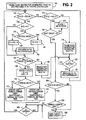
- Figure 2 is a flowchart of a method of controlling a DC motor according to an embodiment of the present invention.
- Figure 2 shows an embodiment of a method for controlling the DC transport motor 35 of the inkjet printer 5 when it is desired to transport an item of print media, such as a piece of paper or an envelope, to a target position for the printing of information in a print swath executed by the shuttle print head assembly 30 on the item of print media.
- such a move when executed by the DC transport motor 35 will typically include at least three states: (1) an acceleration state wherein the DC transport motor 35 is accelerated from a starting velocity (e.g., zero), (2) a slewing state wherein the DC transport motor 35 slews at a certain velocity for a period of time, and (3) a deceleration state wherein the DC transport motor 35 decelerates from the slewing velocity to a resting state so that printing can begin (in addition, a fourth, hold state is implemented as an aspect of the present invention).
- the motion of the DC transport motor 35 according to these states is determined by the output of the trajectory generator implemented in the microprocessor 10.
- the DC motor control method includes calculating a deceleration position (i.e.., the position where deceleration will begin) in the microprocessor 10.
- the calculated deceleration position is one which, when the deceleration is executed at the specified rate, will result in the item of print media stopping short of the target position.
- This deceleration position is preferably specified in terms of a particular encoder count of the encoder 45.
- the method begins at step 100, wherein based on a request from a movement requester, such as a print renderer of the inkjet printer 5, to move the item of print media to a requested target position (which corresponds to a requested target position of the DC transport motor 35), the trajectory generator implemented in the microprocessor 10 generates the first desired position Pd and provides that Pd to the PID controller of motor control subsystem 50.
- a desired position Pd is provided to the PID controller according to some periodic time interval ⁇ T, such as 500 ⁇ s.
- step 120 a determination is made as to whether ⁇ T has elapsed since the time that the prior Pd was provided to the PID controller. If the answer is no, then the method returns to step 120 to await the elapse of ⁇ T. If the answer at step 120 is yes, then, at step 125 the current Pd (generated in step 115) is provided to the PID controller and the method returns to step 105.
- step 105 if the answer is yes, meaning that the current state of the DC transport motor 35 is the deceleration state, then the method proceeds to step 130, wherein the acceleration of the DC transport motor 35 is calculated and a determination is made as to whether the calculated acceleration equals zero (i.e., has zero velocity been reached?). If the answer is no at step 130, meaning the DC transport motor 35 is still decelerating and zero velocity has not been reached, then the method proceeds to step 155 (described below). If, however, the answer at step 130 is yes, meaning zero velocity has been reached (i.e., deceleration is complete), then, at step 135, a determination is made as to whether the requested move is a critical move.
- step 140 the desired position Pd is incremented by four encoder counts and, at step 150, that new Pd is provided to the PID controller. If the answer at step 135 is yes, then, at step 145, the desired position Pd is incremented by one encoder count and, at step 150, that new desired position Pd is provided to the PID controller.
- step 155 a determination is made as to whether the current desired position Pd is greater than or equal to the requested target position. If the answer is no, then, at step 160, the trajectory generator implemented in the microprocessor 10 generates the next desired position Pd based on the current desired position Pd and the DC transport motor 35 velocity from the deceleration profile being employed by the trajectory generator. The method then proceeds to step 120 to await the elapse of ⁇ T, after which the then current desired position Pd will be provided to the PID controller.
- step 155 If, however, the answer at step 155 is yes, meaning that the requested target position has been met or exceeded, then, at step 165, the state of the DC transport motor 35 is set to the hold state, and the velocity and acceleration of the DC transport motor 35 are set to zero. Then, at step 170, a determination is made as to whether the requested move is a critical move. Based on the answer, two different variables will be set which, as described below, are used in the processing after the hold state has been reached. The first of those variables is an Error Limit, and the second of those variables is a Wait Count.
- the Error Limit is set to an error value (NormalErrorLimit) that has been established for use with non-critical moves, and the Wait Count is set to a motor settling time value (NormalSettlingTime) that has been established for use with non-critical moves.
- the Error Limit is set to an error value (CriticalErrorLimit) that has been established for use with critical moves, and the Wait Count is set to a motor settling time value (CriticalSettlingTime) that has been established for use with critical moves.
- step 185 a determination is made as to whether ⁇ T has elapsed since last entering step 105. If the answer is yes, the method returns to step 105, and if the answer is no, the method waits for ⁇ T to elapse.
- step 110 the processing that is performed after the DC transport motor 35 is placed in the hold state will be discussed.
- the method proceeds to step 190.
- step 190 a determination is made as to whether the Wait Count variable is greater than zero. If the answer is yes, then, at step 195, a determination is made as to whether the requested move is a critical move. If the answer is yes, meaning it is a critical move, then, at step 200, a determination is made as to whether a calculated position error equal to the current desired position minus the current actual position of the item of print media as indicated by the encoder 45 is less than the Error Limit established in step 180.
- step 185 the method returns to step 185 to await the elapse of ⁇ T. If, however, the answer at step 200 is yes, then, at step 205, the Wait Count variable is decremented by 1, and the method proceeds to step 185 to await the elapse of ⁇ T. If the answer at step 200 is no, meaning the requested move is not a critical move, then the method proceeds directly to step 205, wherein the Wait Count variable is decremented by 1. The method then proceeds to step 185 to await the elapse of ⁇ T.
- step 210 the requested move is declared to be completed. Thereafter, the movement requester that requested the move, such as a print renderer of the inkjet printer 5, will be informed of the actual ending position of the item of print media. Based on that information, the movement requester may adjust its data, if necessary, in order to optimize the print (e.g., to cause information to be aligned between two print swaths).
- the movement requester may adjust its data, if necessary, in order to optimize the print (e.g., to cause information to be aligned between two print swaths).
- the DC motor control method of the present invention avoids overshoot by calculating and employing a deceleration position (i.e.., the position where deceleration will begin) wherein, when the deceleration is executed at the specified rate, the deceleration will result in the item of print media stopping short of the requested target position.
- a deceleration position i.e.., the position where deceleration will begin
- the method will cause the DC transport motor 35 to creep up on the requested target position using different velocities depending on whether the requested move is a critical move.
- the DC transport motor 35 will be caused to creep at a faster velocity (e.g., four encoder counts per ⁇ T) if the move is non-critical, and a relatively slower velocity (e.g., one encoder counts per ⁇ T) if the move is critical.
- a shorter settling time for the DC transport motor 35 will be employed if the move is non-critical, and a relatively longer settling time will be employed if the move is critical.
Landscapes
- Engineering & Computer Science (AREA)
- Human Computer Interaction (AREA)
- Manufacturing & Machinery (AREA)
- Physics & Mathematics (AREA)
- General Physics & Mathematics (AREA)
- Automation & Control Theory (AREA)
- Character Spaces And Line Spaces In Printers (AREA)
- Control Of Direct Current Motors (AREA)
Claims (10)
- Procédé de commande d'un moteur à courant continu (35) qui fait partie d'une imprimante et provoque le mouvement d'un support d'impression pour faire en sorte que ledit moteur à courant continu (35) exécute un mouvement demandé vers une position cible demandée d'un rotor dudit moteur à courant continu, ledit moteur à courant continu étant structuré de façon à exécuter un premier type de mouvement et un second type de mouvement différent dudit premier type de mouvement, dans lequel le premier type de mouvement est un mouvement critique permettant d'aligner une première bande d'impression imprimée sur un support d'impression avec une seconde bande d'impression imprimée sur le support d'impression, et dans lequel le second type de mouvement est un mouvement non critique dans lequel le support d'impression est déplacé à une position à laquelle des informations entièrement contenues à l'intérieur d'une bande d'impression unique sont imprimées sur le support d'impression, ledit procédé consistant à :calculer (105) une position du rotor en décélération pour ledit moteur à courant continu, dans lequel, lorsque ladite position du rotor en décélération est atteinte, ledit moteur à courant continu (35) est amené à exécuter une décélération de telle manière que cela conduise à l'arrêt du moteur à courant continu à faible distance de ladite position cible demandée dudit rotor ;après que ledit moteur à courant continu (35) a atteint ladite position du rotor en décélération et que ladite décélération se soit achevée, déterminer (135) si ledit mouvement demandé est un premier type de mouvement ;si ledit mouvement demandé est du premier type de mouvement, faire en sorte (145) que ledit moteur à courant continu (35) se déplace vers ladite position cible demandée dudit rotor à une première vitesse ; etsi ledit mouvement demandé est du second type de mouvement, faire en sorte (140) que ledit moteur à courant continu (35) se déplace vers ladite position cible demandée dudit rotor à une seconde vitesse, ladite seconde vitesse étant supérieure à ladite première vitesse.
- Procédé selon la revendication 1, dans lequel ledit moteur à courant continu (35) est amené à se déplacer sur la base d'une position souhaitée du rotor de moteur déterminée périodiquement (100) qui est fournie à une unité de commande en boucle fermée, dans lequel le fait de faire en sorte que ledit moteur à courant continu se déplace vers ladite position cible demandée dudit rotor à une première vitesse consiste à incrémenter (145) la position courante souhaitée d'une première quantité prédéterminée et à fournir (150) la position souhaitée incrémentée à l'unité de commande en boucle fermée, et dans lequel le fait de faire en sorte que ledit moteur à courant continu se déplace vers ladite position cible demandée dudit rotor à une seconde vitesse consiste à incrémenter (140) la position courante alors souhaitée d'une seconde quantité prédéterminée et à fournir (150) la position incrémentée souhaitée à l'unité de commande en boucle fermée, ladite seconde quantité prédéterminée étant supérieure à ladite première quantité prédéterminée.
- Procédé selon la revendication 2, dans lequel la position du rotor du moteur a pour base un compte fourni par un codeur (45), ladite première quantité prédéterminée étant un premier nombre prédéterminé de comptes du codeur et ladite seconde quantité prédéterminée étant un second nombre prédéterminé de comptes du codeur.
- Procédé selon la revendication 3, dans lequel ledit premier nombre prédéterminé de comptes du codeur est un compte de codeur et ledit second nombre prédéterminé de comptes du codeur est égal à quatre comptes de codeur.
- Procédé selon la revendication 2, dans lequel ladite unité de commande en boucle fermée est un contrôleur PID.
- Procédé selon la revendication 2, dans lequel ledit contrôleur en boucle fermée est choisi dans le groupe constitué d'un contrôleur d'avance/retard et d'un contrôleur PI.
- Procédé selon la revendication 1, dans lequel ledit moteur à courant continu (35) est amené à se déplacer sur la base d'une position souhaitée du moteur déterminée périodiquement, le procédé consistant en outre à :après que ledit moteur à courant continu a atteint ladite position du rotor en décélération, et que ladite décélération s'est achevée, déterminer si la position courante souhaitée est supérieure ou égale à ladite position cible demandée dudit rotor ;si la position courante souhaitée est supérieure ou égale à ladite position cible demandée dudit rotor, déclarer (165) que le moteur à courant continu est dans un état de maintien ; etlorsque ledit moteur à courant continu est dans ledit état de maintien, déclarer (180) que ledit déplacement demandé est achevé après qu'un premier temps de stabilisation s'est écoulé si ledit déplacement demandé est un premier type de mouvement et déclarer (175) que ledit mouvement demandé est achevé après qu'un second temps de stabilisation s'est écoulé si ledit mouvement demandé est le second type de mouvement, ledit second temps de stabilisation étant plus court que ledit premier temps de stabilisation.
- Procédé selon la revendication 1, dans lequel ledit moteur à courant continu est amené à se déplacer sur la base d'une position souhaitée du rotor du moteur déterminée périodiquement et dans lequel ladite position souhaitée du rotor du moteur est déterminée périodiquement sur la base d'une période de temps spécifiée, le procédé consistant en outre à :après que ledit moteur à courant continu (35) a atteint ladite position du rotor en décélération, et que ladite décélération s'est achevée, déterminer si la position courante souhaitée est supérieure ou égale à ladite position cible demandée ;si la position courante souhaitée est supérieure ou égale à ladite position cible demandée, déclarer (165) que le moteur à courant continu (35) est dans un état de maintien ;si ledit mouvement demandé est un premier type de mouvement, régler (180) un compte d'attente à une première valeur de compte d'attente et si ledit mouvement demandé est un second type de mouvement, régler (175) le compte d'attente à une seconde valeur de compte d'attente ; etlorsque ledit moteur à courant continu (35) est dans ledit état de maintien, effectuer ce qui suit chaque fois que ladite période de temps spécifiée s'est écoulée :déterminer (190) si ledit compte d'attente est supérieur à zéro ;si ledit compte d'attente n'est pas supérieur à zéro, déclarer (210) que ledit mouvement demandé est achevé ; etsi ledit compte est supérieur à zéro : (i) décrémenter (205) ledit compte d'attente si ledit mouvement demandé est un second type de mouvement, et (ii) décrémenter (205) ledit compte d'attente si ledit mouvement demandé est un premier type de mouvement et si une erreur est inférieure à une limite d'erreur prédéterminée (200), ladite erreur étant une différence entre la position courante alors souhaitée et une position effective du rotor dudit moteur à courant continu (35).
- Procédé selon l'une quelconque des revendications précédentes, dans lequel ladite imprimante est une imprimante à jet d'encre.
- Imprimante comprenant :un moteur de transport à courant continu (35) destiné à déplacer un support d'impression vers une position cible demandée d'un rotor dudit moteur à courant continu selon un mouvement demandé, ledit moteur de transport à courant continu étant structuré de façon à exécuter un premier type de mouvement et un second type de mouvement différent dudit premier type de mouvement, dans lequel le premier type de mouvement est un mouvement critique permettant d'aligner une première bande d'impression imprimée sur un support d'impression avec une seconde bande d'impression imprimée sur le support d'impression, et dans lequel le second type de mouvement est un mouvement non critique dans lequel le support d'impression est déplacé à une position à laquelle des informations entièrement contenues à l'intérieur d'une bande d'impression unique sont imprimées sur le support d'impression ;un dispositif de traitement (10) fonctionnellement relié audit moteur de transport à courant continu (35), ledit dispositif de traitement étant conçu pour :calculer une position du rotor en décélération pour ledit moteur de transport à courant continu (35), dans lequel, lorsque ladite position du rotor en décélération est atteinte, ledit moteur de transport à courant continu est amené à exécuter une décélération de telle manière que cela conduise à l'arrêt du moteur de transport à courant continu à faible distance de ladite position cible demandée dudit rotor ;après que ledit moteur de transport à courant continu a atteint ladite position du rotor en décélération et que ladite décélération s'est achevée, déterminer (135) si ledit mouvement demandé est d'un premier type de mouvement ;si ledit mouvement demandé est du premier type de mouvement, faire en sorte (145) que ledit moteur de transport à courant continu se déplace vers ladite position cible demandée dudit rotor à une première vitesse ; etsi ledit mouvement demandé est du second type de mouvement, faire en sorte (140) que ledit moteur de transport à courant continu (35) se déplace vers ladite position cible demandée dudit rotor à une seconde vitesse, ladite seconde vitesse étant supérieure à ladite première vitesse.
Applications Claiming Priority (1)
| Application Number | Priority Date | Filing Date | Title |
|---|---|---|---|
| US11/950,096 US7898207B2 (en) | 2007-12-04 | 2007-12-04 | Method for controlling a DC motor |
Publications (2)
| Publication Number | Publication Date |
|---|---|
| EP2068217A1 EP2068217A1 (fr) | 2009-06-10 |
| EP2068217B1 true EP2068217B1 (fr) | 2010-09-22 |
Family
ID=40383678
Family Applications (1)
| Application Number | Title | Priority Date | Filing Date |
|---|---|---|---|
| EP08020624A Not-in-force EP2068217B1 (fr) | 2007-12-04 | 2008-11-27 | Procédé de contrôle de moteur CC |
Country Status (3)
| Country | Link |
|---|---|
| US (1) | US7898207B2 (fr) |
| EP (1) | EP2068217B1 (fr) |
| DE (1) | DE602008002682D1 (fr) |
Families Citing this family (4)
| Publication number | Priority date | Publication date | Assignee | Title |
|---|---|---|---|---|
| JP5707129B2 (ja) * | 2010-12-28 | 2015-04-22 | Thk株式会社 | モータ制御装置、モータ制御方法、及び制御プログラム |
| GB2547678A (en) * | 2016-02-25 | 2017-08-30 | Johnson Electric Sa | Method of maintaining a position of an airflow-direction control element of a HVAC system |
| JP7722008B2 (ja) * | 2021-07-26 | 2025-08-13 | ブラザー工業株式会社 | 搬送装置および画像記録装置 |
| CN117656659B (zh) * | 2023-12-30 | 2025-12-12 | 宁波得力科贝技术有限公司 | 喷墨打印机的字车动态控制方法及喷墨打印机 |
Family Cites Families (13)
| Publication number | Priority date | Publication date | Assignee | Title |
|---|---|---|---|---|
| JPS58151885A (ja) | 1982-03-03 | 1983-09-09 | Hitachi Ltd | モ−タの位置制御方法 |
| US4591969A (en) | 1983-08-11 | 1986-05-27 | International Business Machines Corporation | Microprocessor-controlled positioning system |
| US4988935A (en) | 1989-05-24 | 1991-01-29 | Universal Instruments Corporation | Advanced digital motion control |
| GB9601753D0 (en) | 1996-01-29 | 1996-03-27 | Switched Reluctance Drives Ltd | Dual mode position control systems with speed profiling |
| US5844394A (en) * | 1996-09-20 | 1998-12-01 | Matsushita Electric Industrial Co., Ltd. | Stepping motor controller |
| US6249495B1 (en) * | 1997-02-27 | 2001-06-19 | Matsushita Electric Industrial Co., Ltd. | Stepping motor control method and disk drive apparatus |
| CN1520024A (zh) * | 1998-07-16 | 2004-08-11 | ������������ʽ���� | 不带位置传感器的电动机的控制方法及其控制装置 |
| JP3859115B2 (ja) * | 1999-07-26 | 2006-12-20 | セイコーエプソン株式会社 | プリンタ用モータの制御装置および制御方法ならびに制御プログラムを記録した記録媒体 |
| DE60135694D1 (de) * | 2000-02-09 | 2008-10-23 | Seiko Epson Corp | Verfahren und Vorrichtung zur Motorsteuerung |
| JP3832712B2 (ja) * | 2000-09-21 | 2006-10-11 | セイコーエプソン株式会社 | 印刷制御装置および制御方法ならびに印刷制御プログラムを記録した記録媒体 |
| JP3658339B2 (ja) | 2001-05-17 | 2005-06-08 | キヤノン株式会社 | モータの制御のための方法及び装置 |
| US7312595B2 (en) * | 2002-07-09 | 2007-12-25 | Denso Corporation | Motor control apparatus |
| JP4552541B2 (ja) * | 2004-07-09 | 2010-09-29 | ブラザー工業株式会社 | キャリッジ駆動制御装置及び方法 |
-
2007
- 2007-12-04 US US11/950,096 patent/US7898207B2/en not_active Expired - Fee Related
-
2008
- 2008-11-27 EP EP08020624A patent/EP2068217B1/fr not_active Not-in-force
- 2008-11-27 DE DE602008002682T patent/DE602008002682D1/de active Active
Also Published As
| Publication number | Publication date |
|---|---|
| US20090141061A1 (en) | 2009-06-04 |
| US7898207B2 (en) | 2011-03-01 |
| DE602008002682D1 (de) | 2010-11-04 |
| EP2068217A1 (fr) | 2009-06-10 |
Similar Documents
| Publication | Publication Date | Title |
|---|---|---|
| US6823132B2 (en) | Method and apparatus for controlling motor | |
| EP2068217B1 (fr) | Procédé de contrôle de moteur CC | |
| US7479751B2 (en) | Elimination of unintended velocity reversals in s-curve velocity profiles | |
| US6418274B2 (en) | Motor control apparatus and motor control method | |
| US20030178958A1 (en) | Apparatus, method and program for controlling an electric motor | |
| EP0077455B1 (fr) | Système de commande de tête d'impression avec contrôle de l'accélération et de la décélération | |
| EP0621085B2 (fr) | Dispositif de commande d'un système à microprocesseur appliqué à un système de traitement de courrier | |
| EP0067715B1 (fr) | Dispositif pour commander le retour à une position zéro d'un élément mobile | |
| US6822411B2 (en) | Method and apparatus for controlling motors | |
| JP2000134992A (ja) | ステップモ―タ制御信号発生システム | |
| EP0372725B1 (fr) | Régulateur de moteur à microprocesseur ayant des cycles de travail discrets | |
| JP3866067B2 (ja) | 直流電動機の駆動方法、直流電動機の駆動装置、シート送り方法、シート送り装置、画像形成装置、および画像読取装置 | |
| US6310459B1 (en) | DC motor control device and control method | |
| US20170282543A1 (en) | Control system and image forming system | |
| US4496892A (en) | Stepper motor controller | |
| US9221262B2 (en) | Carriage interaction compensation | |
| US7121749B2 (en) | Device and method for carriage drive control | |
| US6986615B2 (en) | Backlash reduction | |
| JP2005103835A (ja) | プラテンギャップ調整装置及び印刷装置並びにモータ制御装置 | |
| JP2019166761A (ja) | モーター制御方法およびモーター制御装置 | |
| US12468280B2 (en) | Step-based systems with multiple actuators | |
| US12326352B2 (en) | Electronic device | |
| JPS60236781A (ja) | シリアルプリンタの制御方式 | |
| JP2006224559A (ja) | インクジェットプリンタ | |
| JP2003131891A (ja) | マルチタスク管理方法、コンピュータプログラム、記録媒体、マルチタスク管理システム、装置、及び、プリンタ |
Legal Events
| Date | Code | Title | Description |
|---|---|---|---|
| PUAI | Public reference made under article 153(3) epc to a published international application that has entered the european phase |
Free format text: ORIGINAL CODE: 0009012 |
|
| AK | Designated contracting states |
Kind code of ref document: A1 Designated state(s): AT BE BG CH CY CZ DE DK EE ES FI FR GB GR HR HU IE IS IT LI LT LU LV MC MT NL NO PL PT RO SE SI SK TR |
|
| AX | Request for extension of the european patent |
Extension state: AL BA MK RS |
|
| 17P | Request for examination filed |
Effective date: 20091203 |
|
| AKX | Designation fees paid |
Designated state(s): CH DE FR GB LI |
|
| GRAP | Despatch of communication of intention to grant a patent |
Free format text: ORIGINAL CODE: EPIDOSNIGR1 |
|
| GRAS | Grant fee paid |
Free format text: ORIGINAL CODE: EPIDOSNIGR3 |
|
| GRAA | (expected) grant |
Free format text: ORIGINAL CODE: 0009210 |
|
| AK | Designated contracting states |
Kind code of ref document: B1 Designated state(s): CH DE FR GB LI |
|
| REG | Reference to a national code |
Ref country code: GB Ref legal event code: FG4D |
|
| REG | Reference to a national code |
Ref country code: CH Ref legal event code: EP |
|
| REF | Corresponds to: |
Ref document number: 602008002682 Country of ref document: DE Date of ref document: 20101104 Kind code of ref document: P |
|
| PLBE | No opposition filed within time limit |
Free format text: ORIGINAL CODE: 0009261 |
|
| STAA | Information on the status of an ep patent application or granted ep patent |
Free format text: STATUS: NO OPPOSITION FILED WITHIN TIME LIMIT |
|
| 26N | No opposition filed |
Effective date: 20110623 |
|
| REG | Reference to a national code |
Ref country code: DE Ref legal event code: R097 Ref document number: 602008002682 Country of ref document: DE Effective date: 20110623 |
|
| REG | Reference to a national code |
Ref country code: CH Ref legal event code: PL |
|
| PG25 | Lapsed in a contracting state [announced via postgrant information from national office to epo] |
Ref country code: CH Free format text: LAPSE BECAUSE OF NON-PAYMENT OF DUE FEES Effective date: 20121130 Ref country code: LI Free format text: LAPSE BECAUSE OF NON-PAYMENT OF DUE FEES Effective date: 20121130 |
|
| REG | Reference to a national code |
Ref country code: FR Ref legal event code: PLFP Year of fee payment: 8 |
|
| REG | Reference to a national code |
Ref country code: FR Ref legal event code: PLFP Year of fee payment: 9 |
|
| PGFP | Annual fee paid to national office [announced via postgrant information from national office to epo] |
Ref country code: GB Payment date: 20161128 Year of fee payment: 9 Ref country code: FR Payment date: 20161123 Year of fee payment: 9 Ref country code: DE Payment date: 20161123 Year of fee payment: 9 |
|
| REG | Reference to a national code |
Ref country code: DE Ref legal event code: R119 Ref document number: 602008002682 Country of ref document: DE |
|
| GBPC | Gb: european patent ceased through non-payment of renewal fee |
Effective date: 20171127 |
|
| REG | Reference to a national code |
Ref country code: FR Ref legal event code: ST Effective date: 20180731 |
|
| PG25 | Lapsed in a contracting state [announced via postgrant information from national office to epo] |
Ref country code: FR Free format text: LAPSE BECAUSE OF NON-PAYMENT OF DUE FEES Effective date: 20171130 Ref country code: DE Free format text: LAPSE BECAUSE OF NON-PAYMENT OF DUE FEES Effective date: 20180602 |
|
| PG25 | Lapsed in a contracting state [announced via postgrant information from national office to epo] |
Ref country code: GB Free format text: LAPSE BECAUSE OF NON-PAYMENT OF DUE FEES Effective date: 20171127 |