EP2068282A2 - Verfahren und System für die Detektion der zweiten Bogenebene von Ohrkanalflächen - Google Patents
Verfahren und System für die Detektion der zweiten Bogenebene von Ohrkanalflächen Download PDFInfo
- Publication number
- EP2068282A2 EP2068282A2 EP08170556A EP08170556A EP2068282A2 EP 2068282 A2 EP2068282 A2 EP 2068282A2 EP 08170556 A EP08170556 A EP 08170556A EP 08170556 A EP08170556 A EP 08170556A EP 2068282 A2 EP2068282 A2 EP 2068282A2
- Authority
- EP
- European Patent Office
- Prior art keywords
- plane
- high curvature
- bend
- points
- curvature points
- Prior art date
- Legal status (The legal status is an assumption and is not a legal conclusion. Google has not performed a legal analysis and makes no representation as to the accuracy of the status listed.)
- Granted
Links
Images


Classifications
-
- G—PHYSICS
- G06—COMPUTING OR CALCULATING; COUNTING
- G06T—IMAGE DATA PROCESSING OR GENERATION, IN GENERAL
- G06T19/00—Manipulating three-dimensional [3D] models or images for computer graphics
-
- G—PHYSICS
- G06—COMPUTING OR CALCULATING; COUNTING
- G06F—ELECTRIC DIGITAL DATA PROCESSING
- G06F30/00—Computer-aided design [CAD]
-
- G—PHYSICS
- G06—COMPUTING OR CALCULATING; COUNTING
- G06T—IMAGE DATA PROCESSING OR GENERATION, IN GENERAL
- G06T7/00—Image analysis
- G06T7/10—Segmentation; Edge detection
- G06T7/13—Edge detection
-
- H—ELECTRICITY
- H04—ELECTRIC COMMUNICATION TECHNIQUE
- H04R—LOUDSPEAKERS, MICROPHONES, GRAMOPHONE PICK-UPS OR LIKE ACOUSTIC ELECTROMECHANICAL TRANSDUCERS; ELECTRIC HEARING AIDS; PUBLIC ADDRESS SYSTEMS
- H04R25/00—Electric hearing aids
- H04R25/65—Housing parts, e.g. shells, tips or moulds, or their manufacture
- H04R25/658—Manufacture of housing parts
-
- G—PHYSICS
- G06—COMPUTING OR CALCULATING; COUNTING
- G06T—IMAGE DATA PROCESSING OR GENERATION, IN GENERAL
- G06T2207/00—Indexing scheme for image analysis or image enhancement
- G06T2207/20—Special algorithmic details
- G06T2207/20112—Image segmentation details
- G06T2207/20164—Salient point detection; Corner detection
-
- G—PHYSICS
- G06—COMPUTING OR CALCULATING; COUNTING
- G06T—IMAGE DATA PROCESSING OR GENERATION, IN GENERAL
- G06T2219/00—Indexing scheme for manipulating 3D models or images for computer graphics
- G06T2219/008—Cut plane or projection plane definition
-
- H—ELECTRICITY
- H04—ELECTRIC COMMUNICATION TECHNIQUE
- H04R—LOUDSPEAKERS, MICROPHONES, GRAMOPHONE PICK-UPS OR LIKE ACOUSTIC ELECTROMECHANICAL TRANSDUCERS; ELECTRIC HEARING AIDS; PUBLIC ADDRESS SYSTEMS
- H04R2225/00—Details of deaf aids covered by H04R25/00, not provided for in any of its subgroups
- H04R2225/77—Design aspects, e.g. CAD, of hearing aid tips, moulds or housings
Definitions
- the present invention generally relates to detection of anatomic features in 3D data representing an ear, and more particularly to detecting the second bend plane of the ear canal surface.
- a current trend in hearing aid manufacturing is towards increased digitization and automation.
- hearing aids were designed in a laborious manual process that required a physical manipulation of shapes to produce a hearing aid customized to the geometry of a patient's ear canal.
- This hearing aid manufacturing process has been digitized, and many hearing aids are designed using computer aided design (CAD) software.
- CAD computer aided design
- Such software typically consists of a suite of surface processing tools, such as tools for cutting, rounding, tapering, and sculpting a digital representation of the ear surface.
- One way to achieve automation of the hearing aid manufacturing is to automate the input to the processing tools of the CAD software. For example, instead of requiring a human software operator to place a plane for cutting on the ear surface, the plane can be placed automatically. The operator can then decide if the plane position is desirable, and adjust the plane position if necessary. Such automation has the potential to greatly improve efficiency of hearing aid manufacturing.
- Each ear canal surface has a different shape unique to an individual patient.
- Various anatomical features of ear canal surfaces exist that can be used to define the shape of an ear canal surface. Such features, when accurately detected, can be used as inputs for automatic hearing aid manufacturing. Accordingly, methods for automatically detecting such anatomic features of ear canal surfaces are desirable.
- Embodiments of the present invention provide automatic detection of the second bend plane of the ear canal.
- the second bend plane is a subtle planar feature of the ear canal surface characterized by a bend in the roughly cylindrical ear canal shape.
- the detected second bend plane can be used in automatic manufacturing of hearing aids.
- a region of interest is defined for an ear canal surface by determining lower and upper boundary planes.
- a set of curves is defined in the region of interest running from the lower boundary plane to the upper boundary plane.
- a set of high curvature points is detected from the set of curves.
- the second bend plane is detected based on the set of high curvature points.
- the set of high curvature points can be pruned based on curvature.
- Candidate planes are detected from planes defined by combinations of three high curvature points.
- a neighborhood set of high curvature points is determined for each candidate plane, and the second bend plane is generated by fitting the second bend plane to the largest neighborhood set of high curvature points.
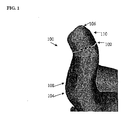
- FIG. 1 illustrates an ear canal portion of a 3D undetailed ear impression
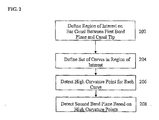
- FIG. 2 illustrates a method for second bend plane detection for an ear canal surface according to an embodiment of the present invention
- FIG. 3 illustrates a method of detecting the second bend plane using a set of high curvature points according to an embodiment of the present invention
- FIG. 4 illustrates exemplary second bend plane detection results using the methods of FIGS. 2 and 3 ;
- FIG. 5 is a high level block diagram of a computer capable of implementing the present invention.
- the present invention relates to a method for detecting the second bend plane of an ear canal surface.
- Embodiments of the present invention are described herein to give a visual understanding of the second bend plane detection method.
- a digital image is often composed of digital representations of one or more objects (or shapes).
- the digital representation of an object is often described herein in terms of identifying and manipulating the objects.
- Such manipulations are virtual manipulations accomplished in the memory or other circuitry / hardware of a computer system. Accordingly, is to be understood that embodiments of the present invention may be performed within a computer system using data stored within the computer system.
- electronic data representing a 3D ear canal surface is manipulated within a computer system in order to detect a location of the second bend plane of the 3D ear canal surface.
- the second bend plane of an ear canal surface is an important feature used for automatic hearing aid manufacturing.
- the ear canal has a roughly cylindrical shape with a first bend at the aperture and a second bend located between the aperture and the ear canal tip.
- the second bend plane is a plane located at the second bend between the first bend plane at the aperture and the canal tip. This feature can be challenging to accurately detect because it is a plane. While it may be fairly easy to identify areas of high curvature on the ear canal, the detection of a plane from this information is not trivial. Even using manual marking of the second bend plane, it can be difficult to exactly determine an accurate placement of the second bend plane.
- FIG. 1 illustrates an ear canal portion of a 3D undetailed ear impression.
- the second bend plane 102 is detected on the ear canal 100 between the first bend plane 104, which is located at the aperture, and the ear canal tip 106.
- FIG. 2 illustrates a method for second bend plane detection for an ear canal surface according to an embodiment of the present invention.
- the method of FIG. 2 transforms digital data of a 3D undetailed ear impression representing the shape of an ear to detect a location of the second bend plane of the ear canal. For example, given a mesh M representing a surface, the method of FIG. 2 detects a second bend plane S of the ear canal.
- the surface model (mesh) M can be generated from a 3D undetailed ear impression.
- a 3D undetailed ear impression is 3D data of an ear generated by a 3D scan of a patient's ear.
- the 3D undetailed ear impression resulting from a 3D scanner is typically a 3D point cloud representing the shape of the scanned ear.
- a computer system performing the steps of the method of FIG. 2 can load a scanned 3D point cloud, for example from a memory or storage of the computer system or from a computer readable medium. Once the 3D point cloud is loaded, it can be triangulated using surface reconstruction techniques to generate a surface M of the 3D undetailed ear impression.
- a region of interest is defined on the ear canal between the first bend plane and the ear canal tip.
- the region of interest R defines a portion of the 3D undetailed ear impression (i.e., the surface mesh M ) where the method searches for the second bend plane S .
- the region of interest R is bounded by two planes parallel to the first bend plane F , forming upper and lower boundaries.
- a set of curves is defined on the ear canal surface in the region of interest. Cutting the 3D undetailed ear impression surface mesh M with the upper and lower boundary planes results in two contours. N corresponding samples are obtained on both the upper and lower contours by traversing both contours simultaneously according to some approximated discrete arc length parameterization. This results in a set of corresponding pairs of sample points on the upper and lower contours. Each pair of these samples points on the upper and lower contours, together with the mid point of a line connecting the centroids of the upper and lower contours, defines a vertical plane P i .
- the 3D undetailed ear impression surface mesh M is cut by each vertical plane P i to extract the points M between the corresponding sample points on the upper and lower contours. Accordingly, each vertical plane P i cuts M in order to define curves that run vertically on M. This results in a set of vertical curves between the lower and upper boundary planes on the ear canal surface. Referring to the 3D undetailed ear impression of FIG. 1 , curves 112, 114, and 116 are defined between the lower boundary plane 108 and the upper boundary plane 110 on the ear canal surface.
- a high curvature point is detected for each of the curves defined on the ear canal surface.
- the set of curves defined in step 204 are used to detect bends in the region of interest R . Accordingly, a set of high curvature points is detected by detecting a high curvature point for each curve in the set of curves.
- the discrete contours resulting from cutting the mesh M with the vertical planes P i may be too noisy for direct curvature estimation. For this reason, a cubic B-spline curve can be fit to each cut to generate a smooth curve, and the point on each smooth curve having the highest value is detected. In order to detect the highest curvature point for each curve, each curve can be sampled numerous times.
- the sampling of each curve may exclude points at either end of each curve, and may slightly shrink the region of interest.
- the second bend plane is detected based on the detected high curvature points.
- a plane representing the second bend plane is fit to the high curvature points of the curves defined in the region of interest.
- FIG. 3 illustrates a method of detecting the second bend plane using a set of high curvature points according to an embodiment of the present invention. Accordingly, step 208 of the method of FIG. 2 can be implemented using the method of FIG. 3 .
- the set of high curvature points is pruned. In order to increase robustness of the subsequent plane fitting, all high curvature points q i with curvature below a threshold t C are removed.
- the threshold t C is the minimal value for a high curvature point of a vertical line on the canal to contribute to the second bend plane detection. The pruning of the high curvature points below t C results in a remaining set Q ' of high curvature points.
- a set of candidate planes are detected based on the normal vectors to the major and minor axes of the bottom plane of the 3D undetailed ear impression (i.e., the shell mesh M ). Examining the bottom plane of the 3D undetailed ear impression, it can be seen that its cut contour can be approximated by an ellipse bearing a major and minor axis.
- n w In order for a plane W to be further considered as a candidate plane, its normal vector n w must have an angle greater than or equal to a threshold t + with the major axis of the bottom plane of the 3D undetailed ear impression (shell mesh M ), and an angle greater than or equal to a threshold t - with the minor axis of the bottom plane of the 3D undetailed ear impression (shell mesh M ).
- This criteria is used to determine candidate planes, as the angle of the normal with respect to the major and minor axes of the bottom plane controls the slope of the plane W . Since a deviation of the normal in the direction of the minor axis is more acceptable that a deviation in the direction of the major axis, the separate thresholds t + and t - are used for the major and minor axes, respectively.
- a neighborhood set of high curvature points is determined for each candidate plane.
- a neighborhood set N of high curvature points is determined as the high curvature points in Q ' that are within a distance threshold t d to W .
- the distance threshold t d defines distance from a plane defined by three seed points, and all high curvature points within this distance are used for fitting the second bend plane.
- the second bend plane is fit to the largest neighborhood set of high curvature points for the candidate planes.
- the largest neighborhood set N defines the point set that is used to define the second bend plane.
- the second bend plane is fit to the points in the largest neighborhood set N , for example using a least squares fit, resulting in a final second bend plane result.
- FIG. 4 illustrates exemplary second bend plane detection results using the methods of FIGS. 2 and 3 .
- second bend plane detection results can be visually displayed in an image representing the ear canal surface.
- images 400, 410, and 420 show exemplary ear canal portions of 3D undetailed ear impression surface meshes.
- a lower boundary contour 402, 412, and 422 and an upper boundary contour 404, 414, and 424 defining the region of interest is shown.
- the second bend plane result 406, 416, and 426 is shown as a contour resulting from cutting the second bend plane with the respective ear canal surface mesh 400, 410, and 420.
- the high curvature points 408, 418, and 428 in the neighborhood set used to define the respective second bend planes 406, 416, and 426 are also shown.
- the second bend plane can be used as a feature in automatic hearing aid manufacturing. Accordingly, the automatic second bend plane detection method can be used in automatically generating/manufacturing hearing aids that are customized to a patient's ear.
- Computer 502 contains a processor 504 which controls the overall operation of the computer 502 by executing computer program instructions which define such operation.
- the computer program instructions may be stored in a storage device 512 (e.g., magnetic disk) and loaded into memory 510 when execution of the computer program instructions is desired.
- a storage device 512 e.g., magnetic disk
- FIGS. 2 and 3 the method steps of the methods of FIGS. 2 and 3 , can be defined by the computer program instructions stored in the memory 510 and/or storage 512 and controlled by the processor 504 executing the computer program instructions.
- the computer 502 also includes one or more network interfaces 506 for communicating with other devices via a network.
- the computer 502 also includes other input/output devices 508 that enable user interaction with the computer 502 (e.g., display, keyboard, mouse, speakers, buttons, etc.)
- input/output devices 508 that enable user interaction with the computer 502 (e.g., display, keyboard, mouse, speakers, buttons, etc.)
- FIG. 5 is a high level representation of some of the components of such a computer for illustrative purposes.
- a computer readable medium encoded with computer executable instructions for second bend plane detection of an ear canal surface the computer executable instructions defining steps comprising; determining lower and upper boundary planes defining a region of interest on an ear canal portion of a 3D undetailed ear impression; defining a set of curves in the region of interest running from the lower boundary plane to the upper boundary plane of the region of interest; detecting a set of high curvature points for the set of curves; and detecting a second bend plane based on the set of high curvature points.
- the computer executable instructions defining the step of determining lower and upper boundary planes defining a region of interest on an ear canal portion of a 3D undetailed ear impression may comprise computer executable instructions defining the step of: determining the lower and upper boundary planes between a first bend plane of the ear canal and an ear canal tip.
- the computer executable instructions defining the step of defining a set of curves in the region of interest running from the lower boundary plane to the upper boundary plane of the region of interest may comprise computer executable instructions defining the steps of: cutting the 3D undetailed ear impression by the upper and lower boundary planes resulting in upper and lower contours on the 3D undetailed ear impression; generating a plurality of corresponding sample points on the upper and lower contours by traversing the upper and lower contours simultaneously according to a discrete arc length parameterization; defining a vertical plane based each pair of corresponding sample points on the upper and lower contours and a mid point of a connecting line of centroids of the upper and lower contours; and cutting the 3D undetailed ear impression with each vertical plane to generate a curve on the 3D undetailed ear impression between each pair of corresponding sample points of the upper and lower contours.
- the computer executable instructions defining the step of detecting a set of high curvature points for the set of curves may comprise computer executable instructions defining the step of detecting a point having a highest curvature for each curve in the set of curves.
- the computer executable instructions defining the step of detecting a second bend plane based on the set of high curvature points may comprise computer executable instructions defining the steps of defining a plane for each possible combination of three high curvature points; detecting a set of candidate planes based on normal vectors between each plane and major and minor axes of a bottom plane of the 3D undetailed ear impression; determining a neighborhood set of high curvature points for each candidate plane; and generating the second bend plane by fitting the second bend plane to a largest neighborhood set of high curvature points.
- the computer executable instructions defining the step of detecting a second bend plane based on the set of high curvature points may further comprise computer executable instructions defining the step of: pruning the set of high curvature points by removing all high curvature points with curvature below a threshold from the set of high curvature points prior to said step of defining a plane for each possible combination of high curvature points.
- the computer executable instructions defining the step of detecting a set of candidate planes based on normal vectors between each plane and major and minor axes of a bottom plane of the 3D undetailed ear impression may comprise computer executable instructions defining the step of determining that a plane is a candidate plane if the normal vector between the plane and the major axis of the bottom plane is greater than or equal to a first threshold and the normal vector between the plane and the minor axis of the bottom plane is greater than or equal to a second threshold.
- the computer executable instructions defining the step of determining a neighborhood set of high curvature points for each candidate plane may comprise computer executable instructions defining the step of: for each candidate plane, defining the neighborhood set of high curvature points as the high curvature points within a certain distance of the candidate plane.
- the computer executable instructions defining the step of generating the second bend plane by fitting the second bend plane to a largest neighborhood set of high curvature points may comprise computer executable instructions defining the step of: fitting the second bend plane to the largest neighborhood set of high curvature points using a least squares fit.
Landscapes
- Engineering & Computer Science (AREA)
- Physics & Mathematics (AREA)
- Theoretical Computer Science (AREA)
- General Physics & Mathematics (AREA)
- Computer Hardware Design (AREA)
- General Engineering & Computer Science (AREA)
- Manufacturing & Machinery (AREA)
- Health & Medical Sciences (AREA)
- Acoustics & Sound (AREA)
- Software Systems (AREA)
- Computer Graphics (AREA)
- General Health & Medical Sciences (AREA)
- Neurosurgery (AREA)
- Otolaryngology (AREA)
- Computer Vision & Pattern Recognition (AREA)
- Signal Processing (AREA)
- Evolutionary Computation (AREA)
- Geometry (AREA)
- Image Analysis (AREA)
- Apparatus For Radiation Diagnosis (AREA)
- Length Measuring Devices By Optical Means (AREA)
- Cultivation Of Plants (AREA)
- Measuring And Recording Apparatus For Diagnosis (AREA)
Applications Claiming Priority (2)
| Application Number | Priority Date | Filing Date | Title |
|---|---|---|---|
| US1213607P | 2007-12-07 | 2007-12-07 | |
| US12/313,600 US8068653B2 (en) | 2007-12-07 | 2008-11-21 | Method and system for second bend plane detection of ear canal surfaces |
Publications (3)
| Publication Number | Publication Date |
|---|---|
| EP2068282A2 true EP2068282A2 (de) | 2009-06-10 |
| EP2068282A3 EP2068282A3 (de) | 2009-08-19 |
| EP2068282B1 EP2068282B1 (de) | 2010-09-29 |
Family
ID=40409935
Family Applications (1)
| Application Number | Title | Priority Date | Filing Date |
|---|---|---|---|
| EP08170556A Not-in-force EP2068282B1 (de) | 2007-12-07 | 2008-12-03 | Verfahren und System für die Detektion der zweiten Bogenebene von Ohrkanalflächen |
Country Status (5)
| Country | Link |
|---|---|
| US (1) | US8068653B2 (de) |
| EP (1) | EP2068282B1 (de) |
| AT (1) | ATE483211T1 (de) |
| DE (1) | DE602008002805D1 (de) |
| DK (1) | DK2068282T3 (de) |
Cited By (1)
| Publication number | Priority date | Publication date | Assignee | Title |
|---|---|---|---|---|
| CN114663402A (zh) * | 2022-03-22 | 2022-06-24 | 深圳蓄能发电有限公司 | 一种基于Hough直线检测和曲线拟合的线缆脱垂检测方法 |
Families Citing this family (1)
| Publication number | Priority date | Publication date | Assignee | Title |
|---|---|---|---|---|
| CN115629078B (zh) * | 2022-10-12 | 2025-07-08 | 中国计量大学 | 一种扁管表面缺陷检测方法 |
Citations (2)
| Publication number | Priority date | Publication date | Assignee | Title |
|---|---|---|---|---|
| EP1345470A2 (de) | 2003-04-03 | 2003-09-17 | Phonak Ag | Verfahren zur Herstellung eines am Körper zu tragenden elektronischen Gerätes, welches an den Form eines Körperteils eines Individuum angepasst ist. |
| US20070189564A1 (en) | 2006-02-03 | 2007-08-16 | Mcbagonluri Fred | System comprising an automated tool and appertaining method for hearing aid design |
Family Cites Families (4)
| Publication number | Priority date | Publication date | Assignee | Title |
|---|---|---|---|---|
| US7991594B2 (en) | 2005-09-13 | 2011-08-02 | Siemens Corporation | Method and apparatus for the rigid registration of 3D ear impression shapes with skeletons |
| US8086427B2 (en) | 2005-09-13 | 2011-12-27 | Siemens Corporation | Method and apparatus for the registration of 3D ear impression models |
| US7814441B2 (en) | 2006-05-09 | 2010-10-12 | Inus Technology, Inc. | System and method for identifying original design intents using 3D scan data |
| US7995817B2 (en) * | 2007-10-16 | 2011-08-09 | Siemens Hearing Instruments, Inc. | System and method for the analysis of basic ear canal taxonomy |
-
2008
- 2008-11-21 US US12/313,600 patent/US8068653B2/en not_active Expired - Fee Related
- 2008-12-03 EP EP08170556A patent/EP2068282B1/de not_active Not-in-force
- 2008-12-03 DK DK08170556.8T patent/DK2068282T3/da active
- 2008-12-03 AT AT08170556T patent/ATE483211T1/de not_active IP Right Cessation
- 2008-12-03 DE DE602008002805T patent/DE602008002805D1/de active Active
Patent Citations (2)
| Publication number | Priority date | Publication date | Assignee | Title |
|---|---|---|---|---|
| EP1345470A2 (de) | 2003-04-03 | 2003-09-17 | Phonak Ag | Verfahren zur Herstellung eines am Körper zu tragenden elektronischen Gerätes, welches an den Form eines Körperteils eines Individuum angepasst ist. |
| US20070189564A1 (en) | 2006-02-03 | 2007-08-16 | Mcbagonluri Fred | System comprising an automated tool and appertaining method for hearing aid design |
Cited By (1)
| Publication number | Priority date | Publication date | Assignee | Title |
|---|---|---|---|---|
| CN114663402A (zh) * | 2022-03-22 | 2022-06-24 | 深圳蓄能发电有限公司 | 一种基于Hough直线检测和曲线拟合的线缆脱垂检测方法 |
Also Published As
| Publication number | Publication date |
|---|---|
| DE602008002805D1 (de) | 2010-11-11 |
| ATE483211T1 (de) | 2010-10-15 |
| DK2068282T3 (da) | 2011-01-24 |
| EP2068282A3 (de) | 2009-08-19 |
| US8068653B2 (en) | 2011-11-29 |
| EP2068282B1 (de) | 2010-09-29 |
| US20090148016A1 (en) | 2009-06-11 |
Similar Documents
| Publication | Publication Date | Title |
|---|---|---|
| CN111798571B (zh) | 牙齿扫描方法、装置、系统和计算机可读存储介质 | |
| JP6385318B2 (ja) | 3d医用画像中の対象物をセグメンテーションするための3d対象物の変換 | |
| CN109712131B (zh) | 肺结节特征的量化方法、装置、电子设备及存储介质 | |
| US7801708B2 (en) | Method and apparatus for the rigid and non-rigid registration of 3D shapes | |
| JPH11149562A (ja) | 曲線セグメントのコーナーの特性付け | |
| CN104715475B (zh) | 一种基于调和场的牙颌三维模型自动分割全部牙冠的方法 | |
| CN109727240B (zh) | 一种三维超声图像的遮挡组织剥离方法及相关装置 | |
| EP2003598A1 (de) | Verfahren und System zur seitlichen Erkennung undetaillierter 3D-Höreindrücke | |
| CN115793571B (zh) | 基于多模态数据的加工设备控制方法、系统及相关设备 | |
| CN115222711A (zh) | 一种血管中心线提取方法及装置 | |
| CN111539999A (zh) | 基于点云配准的3d地图构建方法、装置、计算机设备及存储介质 | |
| CN113034528A (zh) | 基于影像组学的靶区及危及器官勾画轮廓准确性检验方法 | |
| US8086427B2 (en) | Method and apparatus for the registration of 3D ear impression models | |
| EP2068282B1 (de) | Verfahren und System für die Detektion der zweiten Bogenebene von Ohrkanalflächen | |
| CN104952068B (zh) | 一种脊椎特征点自动识别方法 | |
| EP4352696B1 (de) | Füllen eines netzlochs | |
| WO2019232824A1 (zh) | 生物组织影像识别的方法及其系统、计算机储存介质 | |
| CN117058405B (zh) | 一种基于图像的情绪识别方法、系统、存储介质及终端 | |
| CN107368690B (zh) | 医学影像图片的预处理方法及装置 | |
| WO2025015770A1 (zh) | 图像处理方法、装置、程序产品、成像设备和手术机器人 | |
| EP1761109A2 (de) | Verfahren und Vorrichtung für das Aufteilen einer Oberfläche mit geodesischem Abstandsmaß | |
| CN115810015A (zh) | 基于深度学习的膝关节自动分割方法、系统、介质及设备 | |
| JP4164166B2 (ja) | 照射領域抽出装置、照射領域抽出方法及びコンピュータ読み取り可能な記憶媒体 | |
| Riel-Salvatore et al. | Palaeolithic archaeology and 3D visualization technology: recent developments | |
| JP2768627B2 (ja) | 超音波画像処理装置 |
Legal Events
| Date | Code | Title | Description |
|---|---|---|---|
| PUAI | Public reference made under article 153(3) epc to a published international application that has entered the european phase |
Free format text: ORIGINAL CODE: 0009012 |
|
| AK | Designated contracting states |
Kind code of ref document: A2 Designated state(s): AT BE BG CH CY CZ DE DK EE ES FI FR GB GR HR HU IE IS IT LI LT LU LV MC MT NL NO PL PT RO SE SI SK TR |
|
| AX | Request for extension of the european patent |
Extension state: AL BA MK RS |
|
| PUAL | Search report despatched |
Free format text: ORIGINAL CODE: 0009013 |
|
| AK | Designated contracting states |
Kind code of ref document: A3 Designated state(s): AT BE BG CH CY CZ DE DK EE ES FI FR GB GR HR HU IE IS IT LI LT LU LV MC MT NL NO PL PT RO SE SI SK TR |
|
| AX | Request for extension of the european patent |
Extension state: AL BA MK RS |
|
| RIC1 | Information provided on ipc code assigned before grant |
Ipc: G06T 17/20 20060101AFI20090402BHEP Ipc: G06T 17/40 20060101ALI20090716BHEP |
|
| 17P | Request for examination filed |
Effective date: 20100119 |
|
| GRAP | Despatch of communication of intention to grant a patent |
Free format text: ORIGINAL CODE: EPIDOSNIGR1 |
|
| AKX | Designation fees paid |
Designated state(s): AT BE BG CH CY CZ DE DK EE ES FI FR GB GR HR HU IE IS IT LI LT LU LV MC MT NL NO PL PT RO SE SI SK TR |
|
| GRAS | Grant fee paid |
Free format text: ORIGINAL CODE: EPIDOSNIGR3 |
|
| GRAA | (expected) grant |
Free format text: ORIGINAL CODE: 0009210 |
|
| RAP1 | Party data changed (applicant data changed or rights of an application transferred) |
Owner name: SIEMENS CORPORATION |
|
| AK | Designated contracting states |
Kind code of ref document: B1 Designated state(s): AT BE BG CH CY CZ DE DK EE ES FI FR GB GR HR HU IE IS IT LI LT LU LV MC MT NL NO PL PT RO SE SI SK TR |
|
| REG | Reference to a national code |
Ref country code: GB Ref legal event code: FG4D |
|
| REG | Reference to a national code |
Ref country code: CH Ref legal event code: EP |
|
| REG | Reference to a national code |
Ref country code: CH Ref legal event code: NV Representative=s name: SIEMENS SCHWEIZ AG |
|
| REG | Reference to a national code |
Ref country code: IE Ref legal event code: FG4D |
|
| REF | Corresponds to: |
Ref document number: 602008002805 Country of ref document: DE Date of ref document: 20101111 Kind code of ref document: P |
|
| REG | Reference to a national code |
Ref country code: DK Ref legal event code: T3 |
|
| PG25 | Lapsed in a contracting state [announced via postgrant information from national office to epo] |
Ref country code: NO Free format text: LAPSE BECAUSE OF FAILURE TO SUBMIT A TRANSLATION OF THE DESCRIPTION OR TO PAY THE FEE WITHIN THE PRESCRIBED TIME-LIMIT Effective date: 20101229 Ref country code: LT Free format text: LAPSE BECAUSE OF FAILURE TO SUBMIT A TRANSLATION OF THE DESCRIPTION OR TO PAY THE FEE WITHIN THE PRESCRIBED TIME-LIMIT Effective date: 20100929 Ref country code: FI Free format text: LAPSE BECAUSE OF FAILURE TO SUBMIT A TRANSLATION OF THE DESCRIPTION OR TO PAY THE FEE WITHIN THE PRESCRIBED TIME-LIMIT Effective date: 20100929 Ref country code: AT Free format text: LAPSE BECAUSE OF FAILURE TO SUBMIT A TRANSLATION OF THE DESCRIPTION OR TO PAY THE FEE WITHIN THE PRESCRIBED TIME-LIMIT Effective date: 20100929 |
|
| REG | Reference to a national code |
Ref country code: NL Ref legal event code: VDEP Effective date: 20100929 |
|
| LTIE | Lt: invalidation of european patent or patent extension |
Effective date: 20100929 |
|
| PG25 | Lapsed in a contracting state [announced via postgrant information from national office to epo] |
Ref country code: HR Free format text: LAPSE BECAUSE OF FAILURE TO SUBMIT A TRANSLATION OF THE DESCRIPTION OR TO PAY THE FEE WITHIN THE PRESCRIBED TIME-LIMIT Effective date: 20100929 Ref country code: SI Free format text: LAPSE BECAUSE OF FAILURE TO SUBMIT A TRANSLATION OF THE DESCRIPTION OR TO PAY THE FEE WITHIN THE PRESCRIBED TIME-LIMIT Effective date: 20100929 |
|
| PG25 | Lapsed in a contracting state [announced via postgrant information from national office to epo] |
Ref country code: LV Free format text: LAPSE BECAUSE OF FAILURE TO SUBMIT A TRANSLATION OF THE DESCRIPTION OR TO PAY THE FEE WITHIN THE PRESCRIBED TIME-LIMIT Effective date: 20100929 Ref country code: SE Free format text: LAPSE BECAUSE OF FAILURE TO SUBMIT A TRANSLATION OF THE DESCRIPTION OR TO PAY THE FEE WITHIN THE PRESCRIBED TIME-LIMIT Effective date: 20100929 Ref country code: GR Free format text: LAPSE BECAUSE OF FAILURE TO SUBMIT A TRANSLATION OF THE DESCRIPTION OR TO PAY THE FEE WITHIN THE PRESCRIBED TIME-LIMIT Effective date: 20101230 |
|
| PG25 | Lapsed in a contracting state [announced via postgrant information from national office to epo] |
Ref country code: RO Free format text: LAPSE BECAUSE OF FAILURE TO SUBMIT A TRANSLATION OF THE DESCRIPTION OR TO PAY THE FEE WITHIN THE PRESCRIBED TIME-LIMIT Effective date: 20100929 Ref country code: NL Free format text: LAPSE BECAUSE OF FAILURE TO SUBMIT A TRANSLATION OF THE DESCRIPTION OR TO PAY THE FEE WITHIN THE PRESCRIBED TIME-LIMIT Effective date: 20100929 Ref country code: EE Free format text: LAPSE BECAUSE OF FAILURE TO SUBMIT A TRANSLATION OF THE DESCRIPTION OR TO PAY THE FEE WITHIN THE PRESCRIBED TIME-LIMIT Effective date: 20100929 Ref country code: PT Free format text: LAPSE BECAUSE OF FAILURE TO SUBMIT A TRANSLATION OF THE DESCRIPTION OR TO PAY THE FEE WITHIN THE PRESCRIBED TIME-LIMIT Effective date: 20110131 Ref country code: IT Free format text: LAPSE BECAUSE OF FAILURE TO SUBMIT A TRANSLATION OF THE DESCRIPTION OR TO PAY THE FEE WITHIN THE PRESCRIBED TIME-LIMIT Effective date: 20100929 Ref country code: CZ Free format text: LAPSE BECAUSE OF FAILURE TO SUBMIT A TRANSLATION OF THE DESCRIPTION OR TO PAY THE FEE WITHIN THE PRESCRIBED TIME-LIMIT Effective date: 20100929 Ref country code: IS Free format text: LAPSE BECAUSE OF FAILURE TO SUBMIT A TRANSLATION OF THE DESCRIPTION OR TO PAY THE FEE WITHIN THE PRESCRIBED TIME-LIMIT Effective date: 20110129 Ref country code: SK Free format text: LAPSE BECAUSE OF FAILURE TO SUBMIT A TRANSLATION OF THE DESCRIPTION OR TO PAY THE FEE WITHIN THE PRESCRIBED TIME-LIMIT Effective date: 20100929 |
|
| PG25 | Lapsed in a contracting state [announced via postgrant information from national office to epo] |
Ref country code: BE Free format text: LAPSE BECAUSE OF FAILURE TO SUBMIT A TRANSLATION OF THE DESCRIPTION OR TO PAY THE FEE WITHIN THE PRESCRIBED TIME-LIMIT Effective date: 20100929 |
|
| PG25 | Lapsed in a contracting state [announced via postgrant information from national office to epo] |
Ref country code: ES Free format text: LAPSE BECAUSE OF FAILURE TO SUBMIT A TRANSLATION OF THE DESCRIPTION OR TO PAY THE FEE WITHIN THE PRESCRIBED TIME-LIMIT Effective date: 20110109 Ref country code: MC Free format text: LAPSE BECAUSE OF NON-PAYMENT OF DUE FEES Effective date: 20101231 |
|
| PLBE | No opposition filed within time limit |
Free format text: ORIGINAL CODE: 0009261 |
|
| STAA | Information on the status of an ep patent application or granted ep patent |
Free format text: STATUS: NO OPPOSITION FILED WITHIN TIME LIMIT |
|
| PG25 | Lapsed in a contracting state [announced via postgrant information from national office to epo] |
Ref country code: PL Free format text: LAPSE BECAUSE OF FAILURE TO SUBMIT A TRANSLATION OF THE DESCRIPTION OR TO PAY THE FEE WITHIN THE PRESCRIBED TIME-LIMIT Effective date: 20100929 |
|
| REG | Reference to a national code |
Ref country code: DE Ref legal event code: R097 Ref document number: 602008002805 Country of ref document: DE Effective date: 20110630 |
|
| PG25 | Lapsed in a contracting state [announced via postgrant information from national office to epo] |
Ref country code: IE Free format text: LAPSE BECAUSE OF NON-PAYMENT OF DUE FEES Effective date: 20101203 |
|
| PG25 | Lapsed in a contracting state [announced via postgrant information from national office to epo] |
Ref country code: MT Free format text: LAPSE BECAUSE OF FAILURE TO SUBMIT A TRANSLATION OF THE DESCRIPTION OR TO PAY THE FEE WITHIN THE PRESCRIBED TIME-LIMIT Effective date: 20100929 |
|
| PG25 | Lapsed in a contracting state [announced via postgrant information from national office to epo] |
Ref country code: CY Free format text: LAPSE BECAUSE OF FAILURE TO SUBMIT A TRANSLATION OF THE DESCRIPTION OR TO PAY THE FEE WITHIN THE PRESCRIBED TIME-LIMIT Effective date: 20100929 |
|
| PG25 | Lapsed in a contracting state [announced via postgrant information from national office to epo] |
Ref country code: LU Free format text: LAPSE BECAUSE OF NON-PAYMENT OF DUE FEES Effective date: 20101203 Ref country code: HU Free format text: LAPSE BECAUSE OF FAILURE TO SUBMIT A TRANSLATION OF THE DESCRIPTION OR TO PAY THE FEE WITHIN THE PRESCRIBED TIME-LIMIT Effective date: 20110330 Ref country code: BG Free format text: LAPSE BECAUSE OF FAILURE TO SUBMIT A TRANSLATION OF THE DESCRIPTION OR TO PAY THE FEE WITHIN THE PRESCRIBED TIME-LIMIT Effective date: 20100929 |
|
| PG25 | Lapsed in a contracting state [announced via postgrant information from national office to epo] |
Ref country code: TR Free format text: LAPSE BECAUSE OF FAILURE TO SUBMIT A TRANSLATION OF THE DESCRIPTION OR TO PAY THE FEE WITHIN THE PRESCRIBED TIME-LIMIT Effective date: 20100929 |
|
| PGFP | Annual fee paid to national office [announced via postgrant information from national office to epo] |
Ref country code: DK Payment date: 20121219 Year of fee payment: 5 |
|
| PGFP | Annual fee paid to national office [announced via postgrant information from national office to epo] |
Ref country code: GB Payment date: 20121212 Year of fee payment: 5 |
|
| PGFP | Annual fee paid to national office [announced via postgrant information from national office to epo] |
Ref country code: CH Payment date: 20130312 Year of fee payment: 5 Ref country code: DE Payment date: 20130218 Year of fee payment: 5 Ref country code: FR Payment date: 20130131 Year of fee payment: 5 |
|
| PG25 | Lapsed in a contracting state [announced via postgrant information from national office to epo] |
Ref country code: BG Free format text: LAPSE BECAUSE OF FAILURE TO SUBMIT A TRANSLATION OF THE DESCRIPTION OR TO PAY THE FEE WITHIN THE PRESCRIBED TIME-LIMIT Effective date: 20101229 |
|
| REG | Reference to a national code |
Ref country code: DE Ref legal event code: R119 Ref document number: 602008002805 Country of ref document: DE |
|
| REG | Reference to a national code |
Ref country code: DK Ref legal event code: EBP Effective date: 20131231 |
|
| REG | Reference to a national code |
Ref country code: CH Ref legal event code: PL |
|
| GBPC | Gb: european patent ceased through non-payment of renewal fee |
Effective date: 20131203 |
|
| REG | Reference to a national code |
Ref country code: FR Ref legal event code: ST Effective date: 20140829 |
|
| PG25 | Lapsed in a contracting state [announced via postgrant information from national office to epo] |
Ref country code: CH Free format text: LAPSE BECAUSE OF NON-PAYMENT OF DUE FEES Effective date: 20131231 Ref country code: LI Free format text: LAPSE BECAUSE OF NON-PAYMENT OF DUE FEES Effective date: 20131231 Ref country code: DE Free format text: LAPSE BECAUSE OF NON-PAYMENT OF DUE FEES Effective date: 20140701 |
|
| PG25 | Lapsed in a contracting state [announced via postgrant information from national office to epo] |
Ref country code: GB Free format text: LAPSE BECAUSE OF NON-PAYMENT OF DUE FEES Effective date: 20131203 Ref country code: FR Free format text: LAPSE BECAUSE OF NON-PAYMENT OF DUE FEES Effective date: 20131231 |
|
| REG | Reference to a national code |
Ref country code: DE Ref legal event code: R119 Ref document number: 602008002805 Country of ref document: DE Effective date: 20140701 |
|
| PG25 | Lapsed in a contracting state [announced via postgrant information from national office to epo] |
Ref country code: DK Free format text: LAPSE BECAUSE OF NON-PAYMENT OF DUE FEES Effective date: 20131231 |