EP2068330A2 - Dispositif inductif comprennant un aimant permanent et procédés de fabrication associés - Google Patents
Dispositif inductif comprennant un aimant permanent et procédés de fabrication associés Download PDFInfo
- Publication number
- EP2068330A2 EP2068330A2 EP08021187A EP08021187A EP2068330A2 EP 2068330 A2 EP2068330 A2 EP 2068330A2 EP 08021187 A EP08021187 A EP 08021187A EP 08021187 A EP08021187 A EP 08021187A EP 2068330 A2 EP2068330 A2 EP 2068330A2
- Authority
- EP
- European Patent Office
- Prior art keywords
- core
- permanent magnet
- inductor
- magnet body
- conductive
- Prior art date
- Legal status (The legal status is an assumption and is not a legal conclusion. Google has not performed a legal analysis and makes no representation as to the accuracy of the status listed.)
- Granted
Links
- 238000000034 method Methods 0.000 title claims description 12
- 230000001939 inductive effect Effects 0.000 title description 6
- 229910000859 α-Fe Inorganic materials 0.000 claims abstract description 20
- 230000005293 ferrimagnetic effect Effects 0.000 claims abstract description 10
- 238000007747 plating Methods 0.000 claims abstract description 5
- 229910001053 Nickel-zinc ferrite Inorganic materials 0.000 claims description 8
- 230000005291 magnetic effect Effects 0.000 abstract description 25
- 238000004891 communication Methods 0.000 abstract description 8
- 230000001965 increasing effect Effects 0.000 abstract description 6
- 239000011888 foil Substances 0.000 abstract description 4
- 229910052751 metal Inorganic materials 0.000 abstract description 4
- 239000002184 metal Substances 0.000 abstract description 4
- 239000011162 core material Substances 0.000 description 55
- XEEYBQQBJWHFJM-UHFFFAOYSA-N Iron Chemical compound [Fe] XEEYBQQBJWHFJM-UHFFFAOYSA-N 0.000 description 8
- 230000035699 permeability Effects 0.000 description 7
- 239000004020 conductor Substances 0.000 description 5
- 239000000696 magnetic material Substances 0.000 description 4
- 230000004907 flux Effects 0.000 description 3
- 229910052742 iron Inorganic materials 0.000 description 3
- 239000012256 powdered iron Substances 0.000 description 3
- PXHVJJICTQNCMI-UHFFFAOYSA-N Nickel Chemical compound [Ni] PXHVJJICTQNCMI-UHFFFAOYSA-N 0.000 description 2
- 238000013461 design Methods 0.000 description 2
- 238000010586 diagram Methods 0.000 description 2
- 239000002902 ferrimagnetic material Substances 0.000 description 2
- 238000003780 insertion Methods 0.000 description 2
- 230000037431 insertion Effects 0.000 description 2
- SZVJSHCCFOBDDC-UHFFFAOYSA-N iron(II,III) oxide Inorganic materials O=[Fe]O[Fe]O[Fe]=O SZVJSHCCFOBDDC-UHFFFAOYSA-N 0.000 description 2
- 230000005381 magnetic domain Effects 0.000 description 2
- 239000000463 material Substances 0.000 description 2
- 239000000758 substrate Substances 0.000 description 2
- 230000005330 Barkhausen effect Effects 0.000 description 1
- RYGMFSIKBFXOCR-UHFFFAOYSA-N Copper Chemical compound [Cu] RYGMFSIKBFXOCR-UHFFFAOYSA-N 0.000 description 1
- 101000703343 Escherichia coli (strain K12) Putative peptide chain release factor homolog Proteins 0.000 description 1
- XUIMIQQOPSSXEZ-UHFFFAOYSA-N Silicon Chemical compound [Si] XUIMIQQOPSSXEZ-UHFFFAOYSA-N 0.000 description 1
- 229910000831 Steel Inorganic materials 0.000 description 1
- 230000001154 acute effect Effects 0.000 description 1
- 239000000853 adhesive Substances 0.000 description 1
- 230000001070 adhesive effect Effects 0.000 description 1
- 239000003990 capacitor Substances 0.000 description 1
- 230000001413 cellular effect Effects 0.000 description 1
- 238000000576 coating method Methods 0.000 description 1
- KPLQYGBQNPPQGA-UHFFFAOYSA-N cobalt samarium Chemical compound [Co].[Sm] KPLQYGBQNPPQGA-UHFFFAOYSA-N 0.000 description 1
- 229910052802 copper Inorganic materials 0.000 description 1
- 239000010949 copper Substances 0.000 description 1
- 238000011161 development Methods 0.000 description 1
- 230000018109 developmental process Effects 0.000 description 1
- 239000003989 dielectric material Substances 0.000 description 1
- 230000002500 effect on skin Effects 0.000 description 1
- 230000000694 effects Effects 0.000 description 1
- 239000003302 ferromagnetic material Substances 0.000 description 1
- 239000012212 insulator Substances 0.000 description 1
- 239000010445 mica Substances 0.000 description 1
- 229910052618 mica group Inorganic materials 0.000 description 1
- 229910052759 nickel Inorganic materials 0.000 description 1
- 230000003071 parasitic effect Effects 0.000 description 1
- 239000002245 particle Substances 0.000 description 1
- 239000000843 powder Substances 0.000 description 1
- 238000011160 research Methods 0.000 description 1
- 230000000717 retained effect Effects 0.000 description 1
- 229910052710 silicon Inorganic materials 0.000 description 1
- 239000010703 silicon Substances 0.000 description 1
- 239000007787 solid Substances 0.000 description 1
- 239000010959 steel Substances 0.000 description 1
- 238000012360 testing method Methods 0.000 description 1
- 238000004804 winding Methods 0.000 description 1
Images


Classifications
-
- H—ELECTRICITY
- H01—ELECTRIC ELEMENTS
- H01F—MAGNETS; INDUCTANCES; TRANSFORMERS; SELECTION OF MATERIALS FOR THEIR MAGNETIC PROPERTIES
- H01F17/00—Fixed inductances of the signal type
- H01F17/04—Fixed inductances of the signal type with magnetic core
- H01F17/06—Fixed inductances of the signal type with magnetic core with core substantially closed in itself, e.g. toroid
- H01F17/062—Toroidal core with turns of coil around it
-
- H—ELECTRICITY
- H01—ELECTRIC ELEMENTS
- H01F—MAGNETS; INDUCTANCES; TRANSFORMERS; SELECTION OF MATERIALS FOR THEIR MAGNETIC PROPERTIES
- H01F3/00—Cores, Yokes, or armatures
- H01F3/10—Composite arrangements of magnetic circuits
-
- H—ELECTRICITY
- H01—ELECTRIC ELEMENTS
- H01F—MAGNETS; INDUCTANCES; TRANSFORMERS; SELECTION OF MATERIALS FOR THEIR MAGNETIC PROPERTIES
- H01F1/00—Magnets or magnetic bodies characterised by the magnetic materials therefor; Selection of materials for their magnetic properties
- H01F1/01—Magnets or magnetic bodies characterised by the magnetic materials therefor; Selection of materials for their magnetic properties of inorganic materials
- H01F1/03—Magnets or magnetic bodies characterised by the magnetic materials therefor; Selection of materials for their magnetic properties of inorganic materials characterised by their coercivity
- H01F1/12—Magnets or magnetic bodies characterised by the magnetic materials therefor; Selection of materials for their magnetic properties of inorganic materials characterised by their coercivity of soft-magnetic materials
- H01F1/34—Magnets or magnetic bodies characterised by the magnetic materials therefor; Selection of materials for their magnetic properties of inorganic materials characterised by their coercivity of soft-magnetic materials non-metallic substances, e.g. ferrites
-
- H—ELECTRICITY
- H01—ELECTRIC ELEMENTS
- H01F—MAGNETS; INDUCTANCES; TRANSFORMERS; SELECTION OF MATERIALS FOR THEIR MAGNETIC PROPERTIES
- H01F3/00—Cores, Yokes, or armatures
- H01F3/10—Composite arrangements of magnetic circuits
- H01F2003/103—Magnetic circuits with permanent magnets
-
- Y—GENERAL TAGGING OF NEW TECHNOLOGICAL DEVELOPMENTS; GENERAL TAGGING OF CROSS-SECTIONAL TECHNOLOGIES SPANNING OVER SEVERAL SECTIONS OF THE IPC; TECHNICAL SUBJECTS COVERED BY FORMER USPC CROSS-REFERENCE ART COLLECTIONS [XRACs] AND DIGESTS
- Y10—TECHNICAL SUBJECTS COVERED BY FORMER USPC
- Y10T—TECHNICAL SUBJECTS COVERED BY FORMER US CLASSIFICATION
- Y10T29/00—Metal working
- Y10T29/49—Method of mechanical manufacture
- Y10T29/49002—Electrical device making
- Y10T29/4902—Electromagnet, transformer or inductor
- Y10T29/49073—Electromagnet, transformer or inductor by assembling coil and core
Definitions
- the present invention relates to the field of wireless communications, and, more particularly, to inductors and related methods.
- Inductors are a fundamental electromagnetic component used in to a wide variety of devices, such as actuators, relays, motors, DC-to-DC converters and radio frequency (RF) circuits.
- Inductors having large inductances typically include wires wrapped around a bulk dielectric or ferrimagnetic core, and are used in power converters and relays.
- Radio frequency inductors having small inductances typically are helical coils having an air or ferrite core, and are used in RF circuits and communications equipment.
- Inductors for the microwave region can become too small to fabricate and suffer low efficiency and Q values.
- Conventional RF inductor techniques are often abandoned as a result.
- the ferrite core, or tunable coil slug is unusable above VHF due to eddy current losses in the ferrite.
- Even printed spiral inductors have limited usefulness at microwave frequencies, as magnetic field circulation through silicon substrates results in eddy-current loss, and a higher than normal parasitic capacitance.
- Radio frequency (RF) magnetic materials must be nonconductive or nearly so, for the magnetic fields to penetrate. For instance, inductance drops if a solid core of pure iron or steel is placed inside a RF inductor. Yet, if the same material is finely divided into insulated particles then the inductance increases. This is the basis of pentacarbonyl iron or "powdered iron" inductor cores, in which the powder grains may have insulative coatings, and grains size not much larger than the conductor RF skin depth. Nonconductive, highly magnetic atoms are unknown at room temperature and atmospheric pressure.
- RF magnetic materials may occur naturally only as lodestone or magnetite.
- Magnetic permeability is a phenomenon that happens inside atoms, by atomic spin while dielectric permittivity happens between atoms as the dipole moment of polar molecules.
- the options for new magnetic materials are more limited than for dielectrics, as new types of molecules may be created more readily than new types of atoms.
- Magnetic effects occur inside atoms as spin physics while dielectric effects occur between atoms as dipole moment.
- Ferrimagnetic materials are ferrites and garnets, materials having high bulk resistivities (10 7 ⁇ m) and are usable at RF and microwave frequencies. Ferromagnetic materials are generally metallic, conductive, and unsuitable for RF applications.
- Nickel zinc ferrite cores typically offer high efficiency for a relatively small inductor. However, nickel zinc ferrite is not a perfect insulator. Eddy currents may form due to partial conductivity and resistance losses are exhibited as heat.
- U.S. Pat. No. 5,450,052 to Goldberg, et al . is entitled "Magnetically variable inductor for high power audio and radio frequency applications".
- the patent discloses a magnetically variable inductor for high power, high frequency applications which includes a solenoid with a magnetic core therein, disposed coaxially around a conductor for carrying the high power, high frequency signal, and a variable current source coupled with the solenoid so that a manipulation of the current through the solenoid results in a variable inductance for the conductor.
- a typical RF communication device such as a cellular telephone may use more than 20 inductors.
- a radio frequency (RF) inductor including a core being electrically non-conductive and ferrimagnetic, and having a toroidal shape defining an interior, and a wire coil surrounding at least a portion of the core. At least one permanent magnet body is at a fixed position within the interior of the core, and an electrically conductive RF shielding layer is on the at least one permanent magnet body.
- RF radio frequency
- the core may be ferrite or nickel zinc ferrite.
- the electrically conductive RF shielding layer may be an electrically conductive plating layer surrounding the permanent magnet body or a metal foil surrounding the permanent magnet body, for example.
- the permanent magnet may define a magnetic axis intersecting the core at first and second opposing locations thereof.
- the permanent magnet may comprise a cylindrical permanent magnet or a plurality of button-style magnets arranged in stacked relation, for example.
- a method aspect is directed to making a radio frequency (RF) inductor including providing a core being electrically non-conductive and ferrimagnetic, and having a toroidal shape defining an interior, and positioning a wire coil surrounding at least a portion of the core.
- the method includes positioning at least one permanent magnet body at a fixed position within the interior of the core, and providing an electrically conductive RF shielding layer on the at least one permanent magnet body.
- a magnetic field from a permanent magnet is applied to the inductor core, e.g. a ferrite core, to reduce losses, and the permanent magnet is enclosed with a conductive shield to keep RF fields out.
- the relatively small inductor has increased Q and efficiency and may be applicable to RF communication circuits, for example, as an antenna coupler.
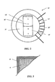
- FIG. 1 is a schematic diagram illustrating an RF inductive device including a shielded and fixed permanent magnet in accordance with an embodiment of the present invention.
- FIG. 2 is a schematic diagram illustrating an RF inductive device including a shielded and fixed permanent magnet in accordance with another embodiment of the present invention.
- FIG. 3 is a cross-sectional view of a portion of the permanent magnet body and associated RF shielding layer according to an embodiment of the invention.
- FIG. 4 is a graph illustrating insertion loss (S 21 ) of a bandstop filter incorporating the RF inductive device of FIG. 2 compared to same using a conventional toroid inductor, in units of decibels.
- the RF inductor 10 includes a core 12 being electrically non-conductive and ferrimagnetic, and having a toroidal shape defining an interior 14.
- the core 12 may be ferrite or nickel zinc ferrite, for example.
- a wire coil 16 surrounds at least a portion of the core 12 .
- a permanent magnet body 18 is at a fixed position within the interior 14 of the core 12.
- An electrically conductive RF shielding layer 20 is on the permanent magnet body 18.
- permanent magnet body 18 may be retained by magnetic attraction to core 12, other ways of fixing the position of the permanent magnet body within the interior core area also contemplated as would be appreciated by this in the art.
- the core 12 and the permanent magnet body 18 may be secured to a substrate, such as a printed circuit board (PCB) by adhesives or a plastic clip.
- PCB printed circuit board
- the permanent magnet body 18 may define a magnetic axis A intersecting the core 12 at first and second opposing locations thereof.
- the permanent magnet body 18 may comprise a cylindrical permanent magnet, as illustrated in Fig. 1 .
- the permanent magnet body 18 may comprise a plurality (e.g. two) of button-style magnets 18' arranged in a stacked relation, for example.
- the present invention includes separate magnetic circuits or paths for magnetic fields: one for "DC" (steady state) H fields and another for RF H fields.
- RF skin effect is used to provide a low pass magnetic circuit in the permanent magnet body 18, as RF magnetic fields will not significantly penetrate conductive materials while DC fields will.
- permanent magnet 18 does not act as a shunt to the RF magnetic fields present around the toroidal magnetic circuit provided by core 12.
- core 12 readily conveys the steady DC magnetic fields of permanent magnet body 18, and the DC field splits into to separate paths around core 12; one clockwise and the other counterclockwise.
- FIG. 4 is a graph that illustrates the measured insertion loss (S 21 ) of a bandstop filter incorporating an example of the RF inductive device 10' of FIG. 2 , compared to the same filter using a conventional toroid inductor.
- the only difference between the filters was the inclusion of permanent magnet body 18 and in increase in the number of turns in wire coil 16.
- Table 1 further details the operating parameters of the conventional device and the present invention: Table 1: Measured Exemplar Filters With And Without The Present Invention Parameter Conventional Inductor Present Invention Inductor Permanent Magnet No Yes, Cobalt Samarium Button Type, Nickel Plated Filter Type Bandstop Bandstop Core Amidon - Micrometals FT-50-67 Amidon - Micrometals FT-50-67 Core Type Nickel Zinc Ferrite Toroid Nickel Zinc Ferrite Toroid Inductor Turns N 2.8 16 Toroid Diameter 1 ⁇ 2 inch 1 ⁇ 2 inch Ferrite Core Magnetic Condition Unbiased Near Saturation Realized Permeability Of Ferrite Core 40 1.21 (Due To Strong Quiescent H Field) Test Frequency 14 MHz 14 MHz Realized Inductance 1.2 ⁇ H 1.2 ⁇ H Inductor Q ⁇ 5.4 ⁇ 304 Filter Center Frequency 14 MHz 14 MHz Capacitance Required For Resonance 110 pf 110 pf Bandstop Filter Rejection (In 50 ohm system) -9.4 d
- the exemplar used a relatively large core with a small number of turns prior to the introduction of the magnet, the larger core being preferential for power handling.
- the capacitor was of the silvered mica type, with negligible losses, so that the filter Q was approximately that of the inductor Q.
- linearity (freedom from intermodulation products or spurious signals) is a design consideration inherent in circuits using ferrite core inductors.
- efficiency and linearity may trade in a complex relationship: for small permanent magnetic bias linearity may actually be improved, especially for flux density remote from saturation. Conversely, linearity may be reduced near saturation.
- linearity relates to magnetic domain grouping or Barkhausen Effect, caused by rapid changes in size of magnetic domains (similarly magnetically oriented atoms in ferrimagnetic materials).
- the inductor core materials include powdered, pentacarbonyl iron type cores which offer greater linearity but are less DC biasable, and ferrites which may be less linear but more easily DC biased for efficiency enhancement. Powdered iron cores generally saturate less easily then do ferrites.
- a method aspect is directed to making a radio frequency (RF) inductor 10, 10' including providing a core 12, 12' being electrically non-conductive and ferrimagnetic, and having a toroidal shape defining an interior 14, 14', and positioning a wire coil 16, 16' surrounding at least a portion of the core.
- the method includes positioning at least one permanent magnet body 18, 18' at a fixed position within the interior 14, 14' of the core 12, 12', and providing an electrically conductive RF shielding layer 20, 20' on the at least one permanent magnet body.
- a quiescent (DC) magnetic field from a permanent magnet 18, 18' is applied to the core, e.g. a ferrite core, to reduce losses, and the permanent magnet is enclosed with a conductive shield 20, 20' , e.g. plated or wrapped in metal foil, to keep RF magnetic fields out.
- the permanent magnet location is inside the ferrite toroid inductor core, e.g. as a Greek ⁇ configuration.
- the relatively small inductor 10, 10' has increased Q and efficiency and may be applicable to RF communication circuits, for example, as an antenna coupler. Higher efficiency ferrite or powdered iron core RF inductors may be accomplished at higher frequencies through the present invention.
Landscapes
- Engineering & Computer Science (AREA)
- Power Engineering (AREA)
- Microelectronics & Electronic Packaging (AREA)
- Chemical & Material Sciences (AREA)
- Composite Materials (AREA)
- Coils Or Transformers For Communication (AREA)
Applications Claiming Priority (1)
| Application Number | Priority Date | Filing Date | Title |
|---|---|---|---|
| US11/951,673 US7940151B2 (en) | 2007-12-06 | 2007-12-06 | Inductive device including permanent magnet and associated methods |
Publications (3)
| Publication Number | Publication Date |
|---|---|
| EP2068330A2 true EP2068330A2 (fr) | 2009-06-10 |
| EP2068330A3 EP2068330A3 (fr) | 2011-12-07 |
| EP2068330B1 EP2068330B1 (fr) | 2012-11-14 |
Family
ID=40381518
Family Applications (1)
| Application Number | Title | Priority Date | Filing Date |
|---|---|---|---|
| EP08021187A Active EP2068330B1 (fr) | 2007-12-06 | 2008-12-05 | Inducteur radiofréquence comprennant un aimant permanent et son procédé de fabrication |
Country Status (4)
| Country | Link |
|---|---|
| US (1) | US7940151B2 (fr) |
| EP (1) | EP2068330B1 (fr) |
| JP (1) | JP5372477B2 (fr) |
| CA (1) | CA2645771C (fr) |
Cited By (3)
| Publication number | Priority date | Publication date | Assignee | Title |
|---|---|---|---|---|
| WO2013030571A1 (fr) * | 2011-08-31 | 2013-03-07 | University College Cardiff Consultants Limited | Limiteur de courant de défaut |
| EP3054592A1 (fr) * | 2015-02-09 | 2016-08-10 | Fu-Tzu Hsu | Dispositif magnétoélectrique capable de stocker de l'énergie électrique utilisable |
| CN111408053A (zh) * | 2020-04-17 | 2020-07-14 | 刘建平 | 一种动静磁场旋磁机及玉石联体 |
Families Citing this family (8)
| Publication number | Priority date | Publication date | Assignee | Title |
|---|---|---|---|---|
| KR20090106492A (ko) | 2006-12-01 | 2009-10-09 | 티티아이 엘뷰 가부시키가이샤 | 경피성 전달 장치와 같은 장치에 전력을 제공하거나 제어하기 위한 시스템, 장치, 및 방법 |
| US9004171B2 (en) | 2012-04-26 | 2015-04-14 | Harris Corporation | System for heating a hydrocarbon resource in a subterranean formation including a magnetic amplifier and related methods |
| US9004170B2 (en) | 2012-04-26 | 2015-04-14 | Harris Corporation | System for heating a hydrocarbon resource in a subterranean formation including a transformer and related methods |
| US9267366B2 (en) | 2013-03-07 | 2016-02-23 | Harris Corporation | Apparatus for heating hydrocarbon resources with magnetic radiator and related methods |
| US9422798B2 (en) | 2013-07-03 | 2016-08-23 | Harris Corporation | Hydrocarbon resource heating apparatus including ferromagnetic transmission line and related methods |
| JP2016149891A (ja) * | 2015-02-13 | 2016-08-18 | 徐 夫子HSU Fu−Tzu | 磁電気装置 |
| CN112863834A (zh) * | 2019-11-28 | 2021-05-28 | 广东美的白色家电技术创新中心有限公司 | 功率因数校正器 |
| CN112820531B (zh) * | 2021-02-02 | 2022-06-24 | 贵州广播电视大学(贵州职业技术学院) | 一种带环形槽基座与永磁体的粘接装置及方法 |
Citations (1)
| Publication number | Priority date | Publication date | Assignee | Title |
|---|---|---|---|---|
| US5450052A (en) | 1993-12-17 | 1995-09-12 | Rockwell International Corp. | Magnetically variable inductor for high power audio and radio frequency applications |
Family Cites Families (17)
| Publication number | Priority date | Publication date | Assignee | Title |
|---|---|---|---|---|
| US2915637A (en) | 1953-11-30 | 1959-12-01 | Int Electronic Res Corp | Tuning system for toroid inductors |
| US3178946A (en) | 1961-12-08 | 1965-04-20 | Security First Nat Bank | Rotating pendulum accelerometer |
| US3946340A (en) | 1974-03-18 | 1976-03-23 | Electromagnetic Sciences, Inc. | Phase shifter |
| US4627292A (en) | 1984-07-03 | 1986-12-09 | Randek Inc. | AC transducers, methods and systems |
| US4723188A (en) | 1986-09-15 | 1988-02-02 | General Electric Company | Permanent magnet surge arrestor for DC power converter |
| JPS63260114A (ja) * | 1987-04-17 | 1988-10-27 | Taiyo Yuden Co Ltd | 永久磁石及びその製造方法 |
| JPH02172209A (ja) * | 1988-12-24 | 1990-07-03 | Tokin Corp | インダクタンス装置 |
| US4975672A (en) * | 1989-11-30 | 1990-12-04 | The United States Of America As Represented By The Administrator Of The National Aeronautics And Space Administration | High power/high frequency inductor |
| JPH09308150A (ja) | 1996-05-10 | 1997-11-28 | Toshiba Corp | 永久磁石回転電機 |
| JPH118111A (ja) * | 1997-06-17 | 1999-01-12 | Tdk Corp | バルントランス用コア材料、バルントランス用コアおよびバルントランス |
| JPH11186072A (ja) * | 1997-12-17 | 1999-07-09 | Urano Ryoichi | 変圧比連続可変型変圧器 |
| JP2005210783A (ja) | 2004-01-20 | 2005-08-04 | Jatco Ltd | 回転機 |
| US7084573B2 (en) | 2004-03-05 | 2006-08-01 | Tokyo Electron Limited | Magnetically enhanced capacitive plasma source for ionized physical vapor deposition |
| JP2005317623A (ja) | 2004-04-27 | 2005-11-10 | Fuji Electric Holdings Co Ltd | 直流リアクトル |
| JP2006086335A (ja) * | 2004-09-16 | 2006-03-30 | Sumida Corporation | 磁気素子、コイル部品、アンテナコイルおよび可変パワーインダクタ |
| US7830065B2 (en) | 2005-01-21 | 2010-11-09 | Chava LLC | Solid state electric generator |
| JP4193942B2 (ja) * | 2005-03-31 | 2008-12-10 | Tdk株式会社 | インダクタンス部品 |
-
2007
- 2007-12-06 US US11/951,673 patent/US7940151B2/en active Active
-
2008
- 2008-12-04 CA CA2645771A patent/CA2645771C/fr not_active Expired - Fee Related
- 2008-12-05 EP EP08021187A patent/EP2068330B1/fr active Active
- 2008-12-05 JP JP2008311330A patent/JP5372477B2/ja not_active Expired - Fee Related
Patent Citations (1)
| Publication number | Priority date | Publication date | Assignee | Title |
|---|---|---|---|---|
| US5450052A (en) | 1993-12-17 | 1995-09-12 | Rockwell International Corp. | Magnetically variable inductor for high power audio and radio frequency applications |
Cited By (8)
| Publication number | Priority date | Publication date | Assignee | Title |
|---|---|---|---|---|
| WO2013030571A1 (fr) * | 2011-08-31 | 2013-03-07 | University College Cardiff Consultants Limited | Limiteur de courant de défaut |
| GB2507901A (en) * | 2011-08-31 | 2014-05-14 | Faultcurrent Ltd | Fault current limiter |
| US9667062B2 (en) | 2011-08-31 | 2017-05-30 | Faultcurrent Limited | Fault current limiter |
| GB2507901B (en) * | 2011-08-31 | 2018-01-24 | Faultcurrent Ltd | Fault current limiter |
| US10680434B2 (en) | 2011-08-31 | 2020-06-09 | Faultcurrent Limited | Fault current limiter |
| EP3054592A1 (fr) * | 2015-02-09 | 2016-08-10 | Fu-Tzu Hsu | Dispositif magnétoélectrique capable de stocker de l'énergie électrique utilisable |
| CN111408053A (zh) * | 2020-04-17 | 2020-07-14 | 刘建平 | 一种动静磁场旋磁机及玉石联体 |
| CN111408053B (zh) * | 2020-04-17 | 2024-04-05 | 刘建平 | 一种动静磁场旋磁机及玉石联体 |
Also Published As
| Publication number | Publication date |
|---|---|
| CA2645771A1 (fr) | 2009-06-06 |
| US7940151B2 (en) | 2011-05-10 |
| US20090146772A1 (en) | 2009-06-11 |
| JP2009141367A (ja) | 2009-06-25 |
| CA2645771C (fr) | 2012-11-27 |
| EP2068330B1 (fr) | 2012-11-14 |
| EP2068330A3 (fr) | 2011-12-07 |
| JP5372477B2 (ja) | 2013-12-18 |
Similar Documents
| Publication | Publication Date | Title |
|---|---|---|
| EP2068330B1 (fr) | Inducteur radiofréquence comprennant un aimant permanent et son procédé de fabrication | |
| US7889026B2 (en) | Electronically variable inductor, associated tunable filter and methods | |
| KR100311924B1 (ko) | 유도성소자용코어와트랜스및인덕터 | |
| US5748013A (en) | Combined magnetic core | |
| CN106664069A (zh) | 共模噪声滤波器 | |
| Ning et al. | A tunable magnetic inductor | |
| US3448421A (en) | Shielded magnetic core | |
| US20200082964A1 (en) | Composite magnetic body, substrate including composite magnetic body, and high-frequency electronic component including same | |
| GB2360137A (en) | Guides for RF magnetic flux | |
| US6873242B2 (en) | Magnetic component | |
| JP2025165995A (ja) | 非可逆回路素子 | |
| KR102483815B1 (ko) | 하이브리드 인덕터 및 이를 이용한 emi 필터 | |
| US20190214184A1 (en) | Inductor with coil conductor formed by conductive material | |
| Lee et al. | Impedance matching of electrically small antenna with Ni-Zn ferrite film | |
| CN111383818B (zh) | Lc复合部件 | |
| CN110945784A (zh) | 电感-电容滤波器及相关联的系统和方法 | |
| US2882527A (en) | Antenna structure | |
| Jung et al. | Development of High-Performance Solenoid-Type RF Chip Inductors Utilizing Low-Loss Al2O3 Core Materials | |
| CN111383820B (zh) | Lc复合部件 | |
| Williams | Fundamentals of magnetics design: Inductors and transformers | |
| Duncan et al. | A survey of the application of ferrites to inductor design | |
| Mercier et al. | Spark plasma sintering co-sintered monolithic transformers for power electronics | |
| WO2019034967A1 (fr) | Film magnétique | |
| Parker et al. | 2.5 Magnetic Materials for Inductive Processes | |
| Verma | Electronic Components III. Inductors |
Legal Events
| Date | Code | Title | Description |
|---|---|---|---|
| PUAI | Public reference made under article 153(3) epc to a published international application that has entered the european phase |
Free format text: ORIGINAL CODE: 0009012 |
|
| 17P | Request for examination filed |
Effective date: 20081205 |
|
| AK | Designated contracting states |
Kind code of ref document: A2 Designated state(s): AT BE BG CH CY CZ DE DK EE ES FI FR GB GR HR HU IE IS IT LI LT LU LV MC MT NL NO PL PT RO SE SI SK TR |
|
| AX | Request for extension of the european patent |
Extension state: AL BA MK RS |
|
| PUAL | Search report despatched |
Free format text: ORIGINAL CODE: 0009013 |
|
| AK | Designated contracting states |
Kind code of ref document: A3 Designated state(s): AT BE BG CH CY CZ DE DK EE ES FI FR GB GR HR HU IE IS IT LI LT LU LV MC MT NL NO PL PT RO SE SI SK TR |
|
| AX | Request for extension of the european patent |
Extension state: AL BA MK RS |
|
| RIC1 | Information provided on ipc code assigned before grant |
Ipc: H01F 3/10 20060101AFI20111103BHEP Ipc: H01F 1/34 20060101ALN20111103BHEP Ipc: H01F 17/06 20060101ALI20111103BHEP |
|
| GRAP | Despatch of communication of intention to grant a patent |
Free format text: ORIGINAL CODE: EPIDOSNIGR1 |
|
| RIC1 | Information provided on ipc code assigned before grant |
Ipc: H01F 1/34 20060101ALN20120203BHEP Ipc: H01F 17/06 20060101ALI20120203BHEP Ipc: H01F 3/10 20060101AFI20120203BHEP |
|
| RTI1 | Title (correction) |
Free format text: RADIO FREQUENCY INDUCTOR INCLUDING PERMANENT MAGNET AND METHOD OF MAKING THEREOF |
|
| GRAS | Grant fee paid |
Free format text: ORIGINAL CODE: EPIDOSNIGR3 |
|
| AKX | Designation fees paid |
Designated state(s): DE FR GB |
|
| GRAA | (expected) grant |
Free format text: ORIGINAL CODE: 0009210 |
|
| AK | Designated contracting states |
Kind code of ref document: B1 Designated state(s): DE FR GB |
|
| REG | Reference to a national code |
Ref country code: GB Ref legal event code: FG4D |
|
| REG | Reference to a national code |
Ref country code: DE Ref legal event code: R096 Ref document number: 602008020052 Country of ref document: DE Effective date: 20130110 |
|
| PLBE | No opposition filed within time limit |
Free format text: ORIGINAL CODE: 0009261 |
|
| STAA | Information on the status of an ep patent application or granted ep patent |
Free format text: STATUS: NO OPPOSITION FILED WITHIN TIME LIMIT |
|
| 26N | No opposition filed |
Effective date: 20130815 |
|
| REG | Reference to a national code |
Ref country code: DE Ref legal event code: R097 Ref document number: 602008020052 Country of ref document: DE Effective date: 20130815 |
|
| PGFP | Annual fee paid to national office [announced via postgrant information from national office to epo] |
Ref country code: GB Payment date: 20141229 Year of fee payment: 7 |
|
| REG | Reference to a national code |
Ref country code: FR Ref legal event code: PLFP Year of fee payment: 8 |
|
| GBPC | Gb: european patent ceased through non-payment of renewal fee |
Effective date: 20151205 |
|
| PG25 | Lapsed in a contracting state [announced via postgrant information from national office to epo] |
Ref country code: GB Free format text: LAPSE BECAUSE OF NON-PAYMENT OF DUE FEES Effective date: 20151205 |
|
| REG | Reference to a national code |
Ref country code: FR Ref legal event code: PLFP Year of fee payment: 9 |
|
| REG | Reference to a national code |
Ref country code: FR Ref legal event code: PLFP Year of fee payment: 10 |
|
| P01 | Opt-out of the competence of the unified patent court (upc) registered |
Effective date: 20230525 |
|
| PGFP | Annual fee paid to national office [announced via postgrant information from national office to epo] |
Ref country code: FR Payment date: 20241226 Year of fee payment: 17 |
|
| PGFP | Annual fee paid to national office [announced via postgrant information from national office to epo] |
Ref country code: DE Payment date: 20241227 Year of fee payment: 17 |