EP2068401A1 - Unité d'antenne - Google Patents
Unité d'antenne Download PDFInfo
- Publication number
- EP2068401A1 EP2068401A1 EP07830798A EP07830798A EP2068401A1 EP 2068401 A1 EP2068401 A1 EP 2068401A1 EP 07830798 A EP07830798 A EP 07830798A EP 07830798 A EP07830798 A EP 07830798A EP 2068401 A1 EP2068401 A1 EP 2068401A1
- Authority
- EP
- European Patent Office
- Prior art keywords
- antenna device
- antenna
- vertical plane
- dipole
- directivity
- Prior art date
- Legal status (The legal status is an assumption and is not a legal conclusion. Google has not performed a legal analysis and makes no representation as to the accuracy of the status listed.)
- Ceased
Links
- 239000002184 metal Substances 0.000 claims abstract description 11
- 239000000758 substrate Substances 0.000 claims description 8
- 230000005855 radiation Effects 0.000 claims description 3
- 230000005684 electric field Effects 0.000 description 6
- 239000004809 Teflon Substances 0.000 description 1
- 229920006362 Teflon® Polymers 0.000 description 1
- 230000015556 catabolic process Effects 0.000 description 1
- 238000006731 degradation reaction Methods 0.000 description 1
- 238000010586 diagram Methods 0.000 description 1
- 238000004519 manufacturing process Methods 0.000 description 1
- 238000012986 modification Methods 0.000 description 1
- 230000004048 modification Effects 0.000 description 1
- 230000003071 parasitic effect Effects 0.000 description 1
Images








Classifications
-
- H—ELECTRICITY
- H01—ELECTRIC ELEMENTS
- H01Q—ANTENNAS, i.e. RADIO AERIALS
- H01Q21/00—Antenna arrays or systems
- H01Q21/06—Arrays of individually energised antenna units similarly polarised and spaced apart
- H01Q21/08—Arrays of individually energised antenna units similarly polarised and spaced apart the units being spaced along or adjacent to a rectilinear path
-
- H—ELECTRICITY
- H01—ELECTRIC ELEMENTS
- H01Q—ANTENNAS, i.e. RADIO AERIALS
- H01Q1/00—Details of, or arrangements associated with, antennas
- H01Q1/27—Adaptation for use in or on movable bodies
- H01Q1/28—Adaptation for use in or on aircraft, missiles, satellites, or balloons
-
- H—ELECTRICITY
- H01—ELECTRIC ELEMENTS
- H01Q—ANTENNAS, i.e. RADIO AERIALS
- H01Q9/00—Electrically-short antennas having dimensions not more than twice the operating wavelength and consisting of conductive active radiating elements
- H01Q9/04—Resonant antennas
- H01Q9/06—Details
- H01Q9/065—Microstrip dipole antennas
-
- H—ELECTRICITY
- H01—ELECTRIC ELEMENTS
- H01Q—ANTENNAS, i.e. RADIO AERIALS
- H01Q9/00—Electrically-short antennas having dimensions not more than twice the operating wavelength and consisting of conductive active radiating elements
- H01Q9/04—Resonant antennas
- H01Q9/16—Resonant antennas with feed intermediate between the extremities of the antenna, e.g. centre-fed dipole
Definitions
- the present invention relates to an antenna device that is provided in a space at least a part of which is surrounded with a metal, and used in a radio communication system based on the MIMO system.
- An IFE (In-Flight Entertainment) system denotes such a system that distributes movie, music, game, etc. to passenger's terminals, and the like in a cabin of an aircraft, or the like.
- a coaxial cable and a server are provided in the ceiling space of the cabin, a client terminal (SEB: Seat Entertainment Box) are provided near the passenger's seats respectively, and the server and the client terminals are connected via the cable using a switching hub, or the like. Since the connection cable must be covered with a protection cover for the purpose of improving durability and fire resistance, such connection cable is heavier than the normal cable and cannot be easily deformed. For this reason, upon changing the arrangement of the passenger seats, it takes much time/labor and cost because the connection cables must be exchanged.
- FIG. 1 shows an IFE system utilizing a radio communication.
- the IFE system shown in FIG. 1 is equipped with a server 11 provided in a ceiling space of a cabin 10, a connection cable 12, a plurality of WAPs (Wireless Access Points) 13, and a plurality of client terminals 14 provided near passenger's seats.
- the plurality of WAPs 13 are connected to the server 11 via the connection cable.
- the WAP 13 and the client terminal 14 have a wireless network interface circuit and an antenna (not shown) respectively, and can hold a radio communication utilizing the wireless LAN based on IEEE802.11a, IEEE802.11b, or IEEE802.11g.
- the communication system utilizing a plurality of WAPs has such a problem that communication quality is degraded on account of a leakage to adjacent channels or an interference of a reflected wave from the wall or the floor. Therefore, a sending power, a directivity of the antenna, and the arrangement of WAPs must be adjusted. However, it is difficult to adjust these factors in the environment such as the aircraft, or the like, which is surrounded with a metal.
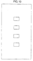
- FIG. 10 a patch antenna containing four rectangular array elements is utilized as the antenna of WAP.
- the directivity of the patch antenna shown in FIG. 10 is illustrated in FIG. 11 and FIG 12 respectively.
- FIG. 11 shows a directivity on a first vertical plane of the patch antenna
- FIG. 12 shows a directivity on a second vertical plane that intersects orthogonally with the first vertical plane of the patch antenna.
- the WAPs are arranged such that the first vertical plane of the patch antenna is provided in the lateral direction of the aircraft and the second vertical plane is provided in the longitudinal direction of the aircraft.
- WAPs are provided on the ceiling space almost just over one aisle out of two rows of aisles in the cabin.
- the patch antenna explained above has the narrow directivity on the second vertical plane (in the longitudinal direction). Therefore, a radio interference with a signal from the adjacent WAP can be avoided by adjusting the sending power of respective WAPs.
- the directivity on the first vertical plane shows a sector shape, but a half-power angle is narrow like about 90 degree.
- a half-power angle of about 144 degree (72x2) on the first vertical plane is needed.
- actually a half-power angle on the first vertical plane is 90 degree, and therefore the electric field strength received at the seat most distant from WAP and next the window is low.
- the present invention provides an antenna device provided in a space at least a part of which is surrounded with a metal and used in a radio communication system based on a MIMO system, the antenna device including a dipole array antenna having a plurality of dipole antennas.
- the dipole array antenna includes three dipole antennas.
- the antenna device further includes a distributor which distributes a signal to each of the plurality of dipole antennas.
- the dipole array antenna and the distributor are provided on a same substrate, and the dipole antennas are provided in vicinity of a ground pattern of the distributor.
- an electrical length from an end of the ground pattern of the distributor to a center of the respective dipole antenna is 1/4 wave length.
- the dipole array antenna is non-directional on a first vertical plane, and a pattern indicating a directivity on a second vertical plane that intersects orthogonally with the first vertical plane has an 8-shaped form.
- a pattern indicating a directivity on a first vertical plane of the dipole array antenna has a cardioid shape
- a radiation pattern on a second vertical plane that intersects orthogonally with the first vertical plane has a main lobe extended on a particular direction and has a null point in other directions.
- the space is an internal space of a fuselage of an aircraft.
- the radio communication system includes an access point and a client terminal, and is used as antennas on a side of the access point.
- a good communication quality can be ensured even in any location in the space at least a part of which is surrounded with the metal.
- an IFE system Like the IFE system utilizing a radio communication shown in FIG. 1 , an IFE system according to a first embodiment of the present invention includes a server 11, a connection cable 12, a plurality of WAPs 13 to which an antenna device 15 is connected respectively, and a plurality of client terminals 14.
- the server 11, the connection cable 12, the plurality of WAPs 13 are provided on the ceiling space of the cabin 10 of the aircraft, the bus, the ship, the train, and the like.
- the server 11 and respective WAPs 13 are connected via the connection cable 12.
- the client terminal 14 is provided near the passenger's seats respectively.
- the WAPs 13 and the client terminals 14 have a wireless network interface circuit (not shown) respectively, and can hold a radio communication utilizing a wireless LAN based on IEEE802.11n. That is, the WAPs 13 and the client terminals 14 exchange a radio communication based on the MIMO (Multi Input Multi Output) system. Therefore, the WAPs 13 and the client terminals 14 utilize an array antenna
- the WASP 13 has a radio module 21, and the antenna device 15 has a three-way distributor 31, and a dipole array antenna 33 with three dipole antennas 35.
- the three-way distributor 31 and the dipole array antenna 33 are connected via coaxial cables 32.
- the signal is distributed into three in-phase signals by the three-way distributor 31.
- Three distributed signals are sent to respective dipole antennas 35 via the coaxial cables 32.
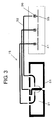
- FIG. 3 shows patterns of the three-way distributor 31 and the dipole array antenna 33 that are provided to the antenna device 15 of the first embodiment.
- the three-way distributor 31 and the dipole array antenna 33 are configured on different substrates respectively.
- Three dipole antennas 35 and three baluns 36 are constructed on a substrate 41 of the dipole array antenna 33.
- the three-way distributor 31 has one input terminal and three output terminals, and a ground pattern 51 is constructed between respective terminals.
- Respective output terminals of the three-way distributor 31 are connected to respective dipole antennas of the dipole array antenna 33 via the coaxial cables 32 and the balun 36, In this case, a length of the coaxial cables 32 is adjusted such that a phase difference between the signals being output from three dipole antennas 35 is set to 10 degree or less.
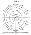
- FIG. 4 shows a directivity on a first vertical plane of the antenna device 15
- FIG. 5 shows a directivity on a second vertical plane of the antenna device 15, which intersects orthogonally with the first vertical plane.
- the antenna device 15 is provided such that the first vertical plane of the antenna device 15 is set in the lateral direction of the aircraft and the second vertical plane is set in the longitudinal direction of the aircraft.
- the WAPs 13 and the antenna devices 15 are provided in the ceiling space almost just over one aisle out of two rows of aisles of the cabin 10.
- a pattern indicating the directivity of the second vertical plane has an 8-shaped form, and the directivity is narrow. Therefore, a radio interference with the signal from the adjacent WAP can be avoided by adjusting the sending power of respective WAPs.
- the pattern is non-directional on the first vertical plane (the lateral direction). Therefore, as shown in FIG. 6 , one WAP 13 and one antenna device 15 covers a zone 61 that contains about three rows of the passenger's seats in the longitudinal direction of the cabin 10. In this case, in order to prevent a radio interference, or the like, a discrete channel that is separated from the channel by three or four channels is assigned to neighboring zones.
- the sending power is adjusted such that the client terminal 14 that is most distant from the antenna device 15 in the zone and next the window can also receive the signal at sufficient electric field strength.
- the client terminal 14 next to the window can receive the signal at sufficient electric field strength, in comparison with the patch antenna whose half-power angle shown in FIG. 11 is about 90 degree.
- the IFE system of the present embodiment is provided in a space at least a part of which is surrounded with a metal, a radio wave radiated from the antenna device 15 is reflected by ceiling, floor, wall, and the like.
- a radio wave radiated from the antenna device 15 is reflected by ceiling, floor, wall, and the like.
- such reflected wave becomes a factor in degradation of a communication quality.
- the MIMO system is utilized in the present embodiment, such reflected wave is utilized positively.
- a difference in the path caused by the reflection is utilized positively in the MIMO system. Therefore, like the present embodiment, the antenna device 15 having a plurality of antennas and the MIMO system are used in combination in a space at least a part of which is surrounded with a metal, the characteristics of both systems can be used efficiently.
- the WAP 13 and the antenna device 15 are constructed as the separate equipment.
- the antenna device 15 may be provided in a case of the WAP 13.
- a different point of an IFE system of a second embodiment from the IFE system of the first embodiment resides in the antenna device,
- the three-way distributor 31 and the dipole array antenna 33 which are provided to the antenna device 15, are constructed on separate substrates respectively.
- the three-way distributor 31 and the dipole array antenna 33 are constructed on the same substrate.
- the three-way distributor 31 and the dipole array antenna 33 are connected by the coaxial cable.
- the three-way distributor 31 and the dipole array antenna 33 are connected directly.
- FIG. 7 shows patterns of the three-way distributor 31 and the dipole array antenna 33 that are provided to an antenna device 75 of a second embodiment. As shown in FIG. 7 , the three-way distributor 31 and the dipole array antenna 33 are constructed on the same substrate 81. The patterns themselves of the three-way distributor 31 and the dipole array antenna 33 are similar to those of the first embodiment.
- the dipole array antenna 33 is constructed such that respective centers (feeding points) of three dipole antennas 35 are provided in a position that is away from an end of the ground pattern 51 of the three-way distributor 31 by an electrical length of about 1/4 wave length,
- the antenna device 75 responds to a frequency in a 5 GHz band and a Teflon (registered trademark) substrate whose dielectric constant is about 2.1 and which has low loss is used
- the dipole array antenna 33 is provided in a position that is away from the end of the ground pattern 51 by about 15 mm.
- the ground pattern when the ground pattern is located in vicinity of the antenna, such ground pattern acts as a parasitic element and gives re-radiation of a radio wave.
- the dipole antennas 35 and the three-way distributor 31 are separated mutually by a 1/4 wave length, a direct radio wave radiated from the dipole antennas 35 and a radio wave re-radiated from the ground pattern 51 cancel each other out. Therefore, the directivity in the direction from the dipole antennas 35 to the three-way distributor 31 shows a null point from which almost no radio wave is radiated.
- the antenna device 75 is arranged such that the null point side is directed toward the ceiling side.
- FIG. 8 shows a directivity on a first vertical plane of the antenna device 75
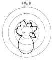
- FIG. 9 shows a directivity on a second vertical plane that intersects orthoganally with the first vertical plane of the antenna device.
- the antenna device 75 is installed such that the first vertical plane is set in the lateral direction of the aircraft and the second vertical plane is set in the longitudinal direction of the aircraft.
- a radiation pattern on the second vertical plane (the longitudinal direction) has a main lobe extended on the particular direction and has a null point in other directions. Since the directivity is narrow, a radio interference with the signal from the adjacent WAP can be avoided by adjusting the sending power of respective WAPs, like the first embodiment.
- a pattern indicating the directivity on the first vertical plane (the lateral direction) has a cardioid shape, and a half-power angle is wide like about 150 degree. Therefore, the client terminal 14 that is most distant from the antenna device 75 and next the window can also receive the signal at sufficient electric field strength.
- the three-way distributor 31 and the dipole array antenna 33 are connected not via the coaxial cable, or the like but directly mutually. Therefore, stability due to a difference in frequencies used in respective channels can be attained and the production at a low cost can be achieved. Also, there is no need to manage respective lengths of the coaxial cables, which is required in the first embodiment, and therefore a design is facilitated.
- the number of distribution is set to 3, and also the number of dipole antennas that the antenna device has is set to 3. But the numbers are not limited to this mode. Any numbers may be employed if the numbers are in excess of 2. Also, in the above embodiment, as shown in FIG. 6 , the case where the WAPs 13 and the antenna devices 15 are provided in the ceiling space almost just over one aisle is explained. But the installing location is not limited to the place just over one aisle, and also the installing area is not limited in the ceiling space.
- the antenna device according to the present invention is useful to the antenna that provides good communication quality in any location in the space at least a part of which is surrounded with the metal when such antenna is provided in the space and used in the radio communication system utilizing the MIMO system.
Landscapes
- Physics & Mathematics (AREA)
- Engineering & Computer Science (AREA)
- Astronomy & Astrophysics (AREA)
- Aviation & Aerospace Engineering (AREA)
- General Physics & Mathematics (AREA)
- Remote Sensing (AREA)
- Variable-Direction Aerials And Aerial Arrays (AREA)
- Details Of Aerials (AREA)
Applications Claiming Priority (2)
| Application Number | Priority Date | Filing Date | Title |
|---|---|---|---|
| JP2006294035A JP5068061B2 (ja) | 2006-10-30 | 2006-10-30 | アンテナ装置 |
| PCT/JP2007/071064 WO2008053856A1 (fr) | 2006-10-30 | 2007-10-29 | Unité d'antenne |
Publications (2)
| Publication Number | Publication Date |
|---|---|
| EP2068401A1 true EP2068401A1 (fr) | 2009-06-10 |
| EP2068401A4 EP2068401A4 (fr) | 2009-09-02 |
Family
ID=39344198
Family Applications (1)
| Application Number | Title | Priority Date | Filing Date |
|---|---|---|---|
| EP07830798A Ceased EP2068401A4 (fr) | 2006-10-30 | 2007-10-29 | Unité d'antenne |
Country Status (4)
| Country | Link |
|---|---|
| US (1) | US20100073250A1 (fr) |
| EP (1) | EP2068401A4 (fr) |
| JP (1) | JP5068061B2 (fr) |
| WO (1) | WO2008053856A1 (fr) |
Cited By (1)
| Publication number | Priority date | Publication date | Assignee | Title |
|---|---|---|---|---|
| WO2015124446A1 (fr) | 2014-02-18 | 2015-08-27 | Latecoere | Procédé et système de transmission de données a bord d'un aéronef |
Families Citing this family (3)
| Publication number | Priority date | Publication date | Assignee | Title |
|---|---|---|---|---|
| JP5857746B2 (ja) | 2009-12-22 | 2016-02-10 | 三菱化学株式会社 | 半導体発光装置用樹脂成形体用材料 |
| DE102016005349B4 (de) | 2016-05-03 | 2018-12-06 | Uwe Dieter Weigele | Verfahren und System zur Lokalisierung einer Störstrahlungsquelle in einem Innenraum eines Fahrzeugs |
| US10313982B1 (en) * | 2017-04-27 | 2019-06-04 | Thales Avionics, Inc. | Cooperative realtime management of noise interference in ISM band |
Family Cites Families (16)
| Publication number | Priority date | Publication date | Assignee | Title |
|---|---|---|---|---|
| US4352200A (en) * | 1979-10-09 | 1982-09-28 | Bell And Howell Company | Wireless aircraft passenger audio entertainment system |
| ES8801066A1 (es) * | 1984-12-20 | 1987-12-01 | Marconi Co Ltd | Una antena de dipolos dispuestos en filas y columnas para ondas electromagneticas. |
| GB2171257A (en) | 1984-12-20 | 1986-08-20 | Marconi Co Ltd | A dipole array |
| JP3114836B2 (ja) * | 1994-01-10 | 2000-12-04 | 株式会社エヌ・ティ・ティ・ドコモ | プリントダイポールアンテナ |
| JP3275819B2 (ja) * | 1998-02-12 | 2002-04-22 | 株式会社デンソー | 情報通信システム |
| JP2000307337A (ja) * | 1999-04-15 | 2000-11-02 | Ntt Docomo Inc | アンテナ装置 |
| FR2794290B1 (fr) | 1999-05-10 | 2007-04-20 | Cit Alcatel | Antenne a polarisation verticale |
| US6285336B1 (en) * | 1999-11-03 | 2001-09-04 | Andrew Corporation | Folded dipole antenna |
| TW578334B (en) * | 2000-07-14 | 2004-03-01 | Hon Hai Prec Ind Co Ltd | Planar printed antenna |
| US6359596B1 (en) * | 2000-07-28 | 2002-03-19 | Lockheed Martin Corporation | Integrated circuit mm-wave antenna structure |
| JP2003324312A (ja) * | 2002-04-30 | 2003-11-14 | Ntt Docomo Inc | 垂直偏波アンテナ |
| US7769398B2 (en) | 2002-11-15 | 2010-08-03 | The Boeing Company | Broadband wireless distribution system for mobile platform interior |
| IE20050033A1 (en) | 2004-04-01 | 2005-10-19 | Naomi Thompson | Antenna construction |
| EP1730812A1 (fr) * | 2004-04-01 | 2006-12-13 | Stella Doradus Waterford Limited | Construction d'antenne |
| JP2006033306A (ja) * | 2004-07-15 | 2006-02-02 | Sony Corp | 無線通信装置およびその制御方法 |
| US7292201B2 (en) * | 2005-08-22 | 2007-11-06 | Airgain, Inc. | Directional antenna system with multi-use elements |
-
2006
- 2006-10-30 JP JP2006294035A patent/JP5068061B2/ja not_active Expired - Fee Related
-
2007
- 2007-10-29 WO PCT/JP2007/071064 patent/WO2008053856A1/fr not_active Ceased
- 2007-10-29 US US12/447,302 patent/US20100073250A1/en not_active Abandoned
- 2007-10-29 EP EP07830798A patent/EP2068401A4/fr not_active Ceased
Cited By (1)
| Publication number | Priority date | Publication date | Assignee | Title |
|---|---|---|---|---|
| WO2015124446A1 (fr) | 2014-02-18 | 2015-08-27 | Latecoere | Procédé et système de transmission de données a bord d'un aéronef |
Also Published As
| Publication number | Publication date |
|---|---|
| EP2068401A4 (fr) | 2009-09-02 |
| WO2008053856A1 (fr) | 2008-05-08 |
| JP5068061B2 (ja) | 2012-11-07 |
| US20100073250A1 (en) | 2010-03-25 |
| JP2008113143A (ja) | 2008-05-15 |
Similar Documents
| Publication | Publication Date | Title |
|---|---|---|
| EP1882382B1 (fr) | Communication avec un avion par les tours d'une station de base cellulaire | |
| US7245938B2 (en) | Wireless antenna traffic matrix | |
| US7345632B2 (en) | Multibeam planar antenna structure and method of fabrication | |
| US10978811B2 (en) | Slot antenna arrays for millimeter-wave communication systems | |
| US20020175862A1 (en) | Antenna array | |
| US20120115548A1 (en) | Mobile communication base station antenna and mobile communication base station antenna system | |
| US11923618B2 (en) | Digital conformal antenna | |
| EP3806240B1 (fr) | Antenne | |
| US20160359237A1 (en) | Wideband antenna star array | |
| US11532874B2 (en) | Antenna system | |
| US10211540B2 (en) | Methods circuits devices assemblies and systems for wireless communication | |
| US6917344B2 (en) | System for isolating an auxiliary antenna from a main antenna mounted in a common antenna assembly | |
| US10461417B2 (en) | Power feed circuit and antenna device | |
| US8768347B2 (en) | Wireless communication system for establishing communication between a base station in a moving vehicle and a wireless terminal | |
| US20100073250A1 (en) | Antenna device | |
| US20180277928A1 (en) | Triple mimo antenna array and wireless network access device | |
| US10218087B2 (en) | Dual band MIMO antenna and wireless access point | |
| US11949165B2 (en) | Antenna device and communication method | |
| WO2008024218A2 (fr) | Agencement d'antenne à bandes multiples | |
| CN110011028B (zh) | 一种天线系统、通讯终端和基站 | |
| US10277288B1 (en) | Method and system for a multi-frequency rail car antenna array | |
| WO2025241932A9 (fr) | Unité d'antenne, antenne, système d'antenne et station de base | |
| WO2014191777A2 (fr) | Système d'antenne, et procédés de transmission et réception à une station de base |
Legal Events
| Date | Code | Title | Description |
|---|---|---|---|
| PUAI | Public reference made under article 153(3) epc to a published international application that has entered the european phase |
Free format text: ORIGINAL CODE: 0009012 |
|
| 17P | Request for examination filed |
Effective date: 20090327 |
|
| AK | Designated contracting states |
Kind code of ref document: A1 Designated state(s): AT BE BG CH CY CZ DE DK EE ES FI FR GB GR HU IE IS IT LI LT LU LV MC MT NL PL PT RO SE SI SK TR |
|
| AX | Request for extension of the european patent |
Extension state: AL BA HR MK RS |
|
| A4 | Supplementary search report drawn up and despatched |
Effective date: 20090804 |
|
| RIC1 | Information provided on ipc code assigned before grant |
Ipc: H01Q 9/06 20060101ALI20090729BHEP Ipc: H01Q 9/16 20060101ALI20090729BHEP Ipc: H01Q 1/38 20060101ALI20090729BHEP Ipc: H01Q 1/28 20060101ALI20090729BHEP Ipc: H01Q 21/08 20060101AFI20080522BHEP |
|
| RBV | Designated contracting states (corrected) |
Designated state(s): FR |
|
| REG | Reference to a national code |
Ref country code: DE Ref legal event code: 8566 |
|
| 17Q | First examination report despatched |
Effective date: 20100218 |
|
| DAX | Request for extension of the european patent (deleted) | ||
| STAA | Information on the status of an ep patent application or granted ep patent |
Free format text: STATUS: THE APPLICATION HAS BEEN REFUSED |
|
| 18R | Application refused |
Effective date: 20120119 |