EP2069201B1 - Vorrichtung zur steuerung des wärmeflusses in einem raumfahrzeug und mit derartiger vorrichtung ausgestattetes raumfahrzeug - Google Patents
Vorrichtung zur steuerung des wärmeflusses in einem raumfahrzeug und mit derartiger vorrichtung ausgestattetes raumfahrzeug Download PDFInfo
- Publication number
- EP2069201B1 EP2069201B1 EP07823806A EP07823806A EP2069201B1 EP 2069201 B1 EP2069201 B1 EP 2069201B1 EP 07823806 A EP07823806 A EP 07823806A EP 07823806 A EP07823806 A EP 07823806A EP 2069201 B1 EP2069201 B1 EP 2069201B1
- Authority
- EP
- European Patent Office
- Prior art keywords
- faces
- heat pipes
- face
- north
- south
- Prior art date
- Legal status (The legal status is an assumption and is not a legal conclusion. Google has not performed a legal analysis and makes no representation as to the accuracy of the status listed.)
- Active
Links
Images




Classifications
-
- B—PERFORMING OPERATIONS; TRANSPORTING
- B64—AIRCRAFT; AVIATION; COSMONAUTICS
- B64G—COSMONAUTICS; VEHICLES OR EQUIPMENT THEREFOR
- B64G1/00—Cosmonautic vehicles
- B64G1/22—Parts of, or equipment specially adapted for fitting in or to, cosmonautic vehicles
- B64G1/46—Arrangements or adaptations of devices for control of environment or living conditions
- B64G1/50—Arrangements or adaptations of devices for control of environment or living conditions for temperature control
-
- B—PERFORMING OPERATIONS; TRANSPORTING
- B64—AIRCRAFT; AVIATION; COSMONAUTICS
- B64G—COSMONAUTICS; VEHICLES OR EQUIPMENT THEREFOR
- B64G1/00—Cosmonautic vehicles
- B64G1/22—Parts of, or equipment specially adapted for fitting in or to, cosmonautic vehicles
- B64G1/46—Arrangements or adaptations of devices for control of environment or living conditions
- B64G1/50—Arrangements or adaptations of devices for control of environment or living conditions for temperature control
- B64G1/506—Heat pipes
-
- F—MECHANICAL ENGINEERING; LIGHTING; HEATING; WEAPONS; BLASTING
- F28—HEAT EXCHANGE IN GENERAL
- F28D—HEAT-EXCHANGE APPARATUS, NOT PROVIDED FOR IN ANOTHER SUBCLASS, IN WHICH THE HEAT-EXCHANGE MEDIA DO NOT COME INTO DIRECT CONTACT
- F28D15/00—Heat-exchange apparatus with the intermediate heat-transfer medium in closed tubes passing into or through the conduit walls ; Heat-exchange apparatus employing intermediate heat-transfer medium or bodies
- F28D15/02—Heat-exchange apparatus with the intermediate heat-transfer medium in closed tubes passing into or through the conduit walls ; Heat-exchange apparatus employing intermediate heat-transfer medium or bodies in which the medium condenses and evaporates, e.g. heat pipes
- F28D15/0275—Arrangements for coupling heat-pipes together or with other structures, e.g. with base blocks; Heat pipe cores
-
- B—PERFORMING OPERATIONS; TRANSPORTING
- B64—AIRCRAFT; AVIATION; COSMONAUTICS
- B64G—COSMONAUTICS; VEHICLES OR EQUIPMENT THEREFOR
- B64G1/00—Cosmonautic vehicles
- B64G1/22—Parts of, or equipment specially adapted for fitting in or to, cosmonautic vehicles
- B64G1/46—Arrangements or adaptations of devices for control of environment or living conditions
- B64G1/50—Arrangements or adaptations of devices for control of environment or living conditions for temperature control
- B64G1/503—Radiator panels
-
- F—MECHANICAL ENGINEERING; LIGHTING; HEATING; WEAPONS; BLASTING
- F28—HEAT EXCHANGE IN GENERAL
- F28D—HEAT-EXCHANGE APPARATUS, NOT PROVIDED FOR IN ANOTHER SUBCLASS, IN WHICH THE HEAT-EXCHANGE MEDIA DO NOT COME INTO DIRECT CONTACT
- F28D21/00—Heat-exchange apparatus not covered by any of the groups F28D1/00 - F28D20/00
- F28D2021/0019—Other heat exchangers for particular applications; Heat exchange systems not otherwise provided for
- F28D2021/0028—Other heat exchangers for particular applications; Heat exchange systems not otherwise provided for for cooling heat generating elements, e.g. for cooling electronic components or electric devices
- F28D2021/0029—Heat sinks
Definitions
- the present invention relates to a thermal flow management device in a spacecraft in orbit.
- the faces of a spacecraft or satellite are subject to variations in the flow of solar rays as a function of their orientation and their distance from the sun. Thus, some faces of the machine do not receive the same amount of thermal energy during a period of twenty-four hours and during the seasons.
- a spacecraft of the geostationary satellite type 1 is in the form of a parallelepipedal casing 2 rotating on an orbit 3 around the Earth 4 and still having the same face directed towards the Earth, this face being called the Earth face 5A, the opposite face and parallel to the Earth face 5A is called the anti-Earth face 5B.
- the North face 6 and the South face 7 of the housing are both opposite to each other, parallel to each other and perpendicular to the North-South axis of the Earth 4 while the east faces 8 and West 9 are two other opposite faces, parallel to each other and perpendicular to the direction of movement of the spacecraft 1.
- North 6 and South 7 faces are relatively exposed to the rays emitted by the sun 10 compared to the East 8 and West 9 faces, which are alternately exposed to these rays during an orbital revolution.
- North 6 and South 7 faces are the faces on which solar panels 11 are fixed and the East 8 and West 9 faces are the faces on which communication antennas are fixed.
- radiative panels having the ability to radiate the power dissipated to the space while minimizing the solar flux absorbed when these panels are exposed to the sun, are provided on the faces. of the satellite.
- the north and south faces are used for heat dissipation because they receive a small amount of solar flux that is relatively constant over time.
- hot springs such as a Progressive Wave Tube (TOP) or OMUX (output multiplexer), which should be also to regulate thermally by dissipation of their thermal energy using these radiators or radiative panels, when they are in use.
- TOP Progressive Wave Tube
- OMUX output multiplexer
- the radiative surface In order to allow a greater dissipation of heat, the radiative surface should be increased. However, the areas usable for thermal radiation are limited by the volume available in the space launcher and the elements already provided on the surface of the satellite, such as antennas.
- one of the main challenges for satellite telecommunication is to achieve the best compromise between the dissipated power, the radiative surfaces and the mass of the satellite.
- a heat flow management system is integrated by placing radiators on the North, South, East and West faces and connecting them to a heat load or heat sink units using variable conductance heat pipes (Variable Conductance Heat). Pipes (VCHP)) or heat-pipe diode (DHP).
- VCHP Variable Conductance Heat
- DHP heat-pipe diode
- this document does not provide for greater heat dissipation of the North and South faces, but instead increases the heat dissipation of the East and West faces by forming a loop of heat pipes passing through the East, West faces. , Earth and anti-Earth.
- this embodiment also does not allow the realization of a thermal flow management device that is autonomous and can operate in all seasons.
- thermal flow control device that is autonomous, can operate in all seasons and fully passive way, that is to say without requiring intervention or a change in its operating mode during the time depending on its position on its orbit.
- a spacecraft comprising a thermal flow management device for improving the heat dissipation capacity of the heat emitted by the north and south faces while operating autonomously, continuous and passive.
- the present invention relates to a spacecraft comprising a thermal flow management device, the spacecraft always having the same face facing the Earth, a pair of opposing faces North and South parallel to each other and perpendicular to the earth.
- the device comprises at least one pair of connection heat pipes with first and second branches, the first branch one of the heat pipes connecting said pair of heat pipes being fixed, in thermal conduction contact, on a radiative panel of the north face, and the first leg of the other of the heat pipes connecting said pair of heat pipes connection being fixed, in thermal conduction contact, on a radiative panel of the south face.
- said first branch of said connection heat pipe is fixed on at least a portion of an extension of the radiative panel either of the north face or of the south face projecting from said other pair opposite faces.
- said first branch of said connection heat pipe is fixed on the inner wall of said radiative panel either of the north face or of the south face, in the interior volume delimited by the faces of said machine spatial.
- said second branch of said connecting heat pipe is fixed on the outer wall of one of the faces belonging to said other pair of opposite faces.
- a radiative panel is fixed on said second branches of said pair of connecting heat pipes.
- said first and second branches of said connection heat pipe are of the same length.
- said second branch of said heat pipe connecting said pair of heat pipes is fixed in thermal conduction contact on another second branch of another heat pipe connecting said pair of heat pipes connection which is itself fixed on the outer wall of one of the faces belonging to said other pair of opposite faces.
- said second branch of said connection heat pipe is of greater length than said first branch of said connection heat pipe.
- a plate preferably aluminum, is fixed on the second branches of said heat pipes connecting the same face belonging to the other pair of opposed faces which are in thermal conduction contact with a second branch of another connection heat pipe.
- said second branch of said connecting heat pipe which is fixed on the second branch of another connection heat pipe comprises a pair of fins tangential to a tubular element in which circulates a coolant, one of the fins being of greater transverse dimension than the other fin.
- North and South faces at least one radiative panel with a honeycomb structure on or in which are associated networks of heat pipes.
- the honeycomb structure comprises a first network of heat pipes housed in cells of said honeycomb and a second network of heat pipes placed externally on a surface of said honeycomb. and perpendicular to the heat pipes of the first network.
- the honeycomb structure comprises a first network of heat pipes housed in cells of said honeycomb and a second network of heat pipes passing through said cells perpendicular to the heat pipes of said first network.
- heat dissipating unit or "heat transmitting unit” must be understood respectively. as any element of the spacecraft 1 adapted to dissipate heat or capable of transmitting heat, it being understood that the term “hot source” is equivalent to these two terms.
- hot source is equivalent to these two terms.
- spacecraft and “satellite” should be considered equivalent.
- a horizontal element is an element substantially parallel or coincident with the EastWest axis while a vertical element is a substantially parallel element or coincident with the North-South axis.
- the north face 6 and the south face 7 of the satellite are considered to be horizontal surfaces and the east face 8, the west face 9, the Earth face 5A and the anti-Earth face 5B (face opposite and parallel to the Earth face 5) are considered to be vertical surfaces, it being understood that, according to the preferred embodiment of a satellite, the assembly these faces forms a parallelepipedal assembly, but that it is also possible to predict, and as illustrated in the figures 17 and 18 , satellites having some faces inclined relative to others.
- the figure 2 is a schematic top view of a radiative panel having a honeycomb support structure 12 adapted to be integrated at least partially in one of the faces 5-9 of the satellite 1.
- each heat pipe 13a, 13b being in the form of a substantially longitudinal tubular element of which internal orifice is filled with a coolant, preferably ammonia.
- a radiating honeycomb panel 12 there is provided a first network 13a of heat pipes integrated in the cells 14 of the honeycomb 12 and a second network 13b of heat pipes provided in perpendicular contact with the heat pipes of the first network 13a, the heat pipes of the second network 13b, being placed externally on a surface of the honeycomb 12, advantageously on the surface of the honeycomb 12 intended to be directed towards the interior of the spacecraft 1.
- the outer surface of the honeycomb 12 that is, that is to say the surface of the honeycomb 12 intended to be directed towards space, is covered by an aluminum plate 15 coated with a reflective coating 16, preferably of the OSR (Optical Solar Reflector) type or, alternatively, a layer of white paint.
- OSR Optical Solar Reflector
- the second network of heat pipes 13c is provided directly integrated in the honeycomb structure 12 with the heat pipes 13c of this second network in contact perpendicularly with the heat pipes of the first network 13a.
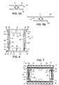
- FIGS. 5A and 5B respectively represent two diagrammatic sectional views of a possible embodiment of a heat pipe 13.
- the heat pipe 13 of known type, consists of a hollow tubular element 17 filled with a coolant, advantageously ammonia, and having a pair of tangential fins 18, parallel to each other and of substantially the same length.
- the fins 18 advantageously make it possible to dissipate the heat stored by the coolant contained in the heat pipe 13.
- the figure 6 is a schematic sectional view of a first embodiment of the device according to the invention for managing heat flows between the North 6 and South 7 faces of a geostationary satellite 1.
- At least one hot source 19 such as a Progressive Wave Tube (TOP) or OMUX (output multiplexer), placed and fixed in thermal conduction contact on a radiative honeycomb panel 12 and more precisely on the heat pipes 13a, 13b, 13c connected to this radiative panel.
- TOP Progressive Wave Tube
- OMUX output multiplexer
- the hot source 19 is either a heat dissipating equipment or a heat transmitting element.
- the North 6 and South 7 faces of the spacecraft 1 are provided with extensions or flange 20, preferably in the form of rectangular plates, projecting from the pair of opposing vertical faces East and West 8, 9 or the pair of opposite vertical faces Earth 5A and anti-Earth 5B.
- the satellite 1 has a first extension 20 of the north face 6 (respectively South 7) in projection of the east face 8 and a second extension 20 of the north face 6 (respectively South 7) projecting from the west face 9, the first and second extensions 20 are both the same size and the same length.
- the satellite 1 has a first extension 20 of the North face 6 (respectively South 7) protruding from the face of the earth 5A and a second extension 20 of the north face 6 (respectively south 7) protruding from the anti-Earth face 5B, the first and the second extensions 20 being both of the same size and the same length.
- the horizontal arm 22 fixed on the inner wall of the North or South face 7 is more precisely fixed on the inner wall of the extension 20 of the North face 6 or South 7 in vis-à-vis the inner wall of the other extension 20 of the North face 6 or South 7.
- a honeycomb plate 24 forming a radiative panel is advantageously fixed on the vertical branches 23 of a pair of connection heat pipes 21 placed on the same vertical face of the spacecraft 1.
- the figure 7 is a detailed schematic sectional view of the device of the figure 6 in which the different radiative panels are as illustrated in FIG. figure 3 .
- the honeycomb plate 12 attached to the at least one pair of L-shaped heat pipes 21 has the structure as described in FIG. figure 3 .
- the vertical branches 23 of the connection heat pipes 21 are in direct contact with the heat pipes 13b of the second network external to the honeycomb structure 12.
- the honeycomb structures 12 installed on the spacecraft 1 are of the type as described in FIG. figure 4 .
- the plates 24 in nest 12 on the at least one pair of connecting heat pipes 21, as well as the radiative honeycomb structures 12 provided at least partly in the North 6 and South 7 faces, are of the type as described in FIG. figure 4 .
- the hot springs 19 are then placed directly on the heat pipes of the first heat pipe network 13a, a network in which the heat pipes are integrated in the cells 14, and the horizontal branches 23 of the connection heat pipes 21 are also directly in contact with the heat pipes 13a of this first network.
- the radiative honeycomb panels 12 described in FIG. figure 4 for the North 6 and South 7 faces and the radiative honeycomb panels 12 described in FIG. figure 3 as a connecting plate 24 between a pair of connecting heat pipes 23 provided on the east face 8, West 9, Earth 5A or anti-Earth 5B.
- the figure 9 is a schematic front perspective view of a spacecraft with, on a vertical face, a radiative plate 24 honeycomb placed on at least one pair of heat pipes 21 L connection.
- the number of L-shaped heat pipes 21 present at each extension 20 of the North 6 and South 7 faces depends on the dimensions of the radiative plate 24 in the honeycomb 12 as well as the number and the distribution of the heat pipes 13a, 13b present in the honeycomb structure 12 faces North 6 and South 7.
- the figure 10 is a schematic sectional view of a second embodiment of the device according to the invention for managing heat flows emitted by hot springs 19 placed in contact with radiative panels of the North 6 and South 7 faces of a geostationary satellite 1 with at least one pair of connecting heat pipes 25 between the north face 6 and the south face 7 of the satellite 1, placed on the same vertical face, in the form of L-shaped heat pipes with a vertical main branch 26 and a horizontal secondary branch 27, the vertical main branch 26 being of greater length than the vertical secondary branch 27.
- the horizontal secondary branch 27 of the connecting heat pipe 25 is intended to be placed in contact against the inner surface of the extension 20 of the North 6 and South 7 faces while the vertical main branch 26 is intended to be placed in contact with the vertical face East, West, Earth or anti-Earth of the satellite 1, or on a vertical main branch 26 of another connecting heat pipe 25.
- a radiative panel in the form of a honeycomb 12 of the type as described in FIG. figure 3 there is provided a radiative panel in the form of a honeycomb 12 of the type as described in FIG. figure 3 .
- a radiative panel in the form of a honeycomb 12 of the type as described in FIG. figure 4 it is also possible to provide a radiative panel in the form of a honeycomb 12 of the type as described in FIG. figure 4 .
- the extensions 20 which are shown projecting from the East 8 and West 9 faces project from the Earth 5A and Anti-Earth 5B faces, and that, consequently, the heat pipes of connection 25 are then placed in relation to these surfaces 5A and 5A Earth anti-Earth, the main vertical branch 26a, 26c of the lower connection heat pipe 25a, 25c then being fixed either on the face 5A Earth or on the anti-Earth face 5B.
- connection heat pipes 25a-25d are intended to capture the heat stored by the horizontal heat pipes integrated in the radiative honeycomb panels 12 of the North 6 and South 7 faces and to transfer it to the other faces of the spacecraft 1 on which they are fixed thus making it possible to obtain a better distribution of the heat emitted by the North 6 and South 7 faces on the other vertical faces of the satellite 1.
- each horizontal external heat pipe 13b of the North 6 and South 7 faces a pair of respective heat pipes 25 consisting of a lower vertical connection heat pipe. 25a, 25c and an upper vertical connection heat pipe 25b, 25d.
- connection heat pipes 25 consisting of a lower vertical connection heat pipe 25a, 25c and an upper vertical connection heat pipe 25b, 25d for two external horizontal heat pipes 13b connected to the radiating panel of the north face 6 and two external horizontal heat pipes 13b connected to the radiative panel of the south face.
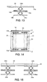
- the figure 13 schematically illustrates a sectional view of a vertical branch 26a of the lower connection pipe 25a on which is placed a vertical branch 26b of the upper connection heat pipe 25b.
- the upper fin 18a of the vertical branch 26b of the upper connecting heat pipe 25b is larger than the lower fin18b of the same vertical leg 26b which is in contact with the upper fin 18a of the vertical leg 26a of the lower connection heat pipe 25a.
- the vertical branch 26b of the upper connection heat pipe 25b is therefore of the type as described in FIG. Figure 5B while the vertical leg 26a of the lower connection heat pipe 25a is of the type as described in the Figure 5A .
- the vertical leg 26b of the upper connecting pipe 25b and the vertical leg 26a of the lower connecting pipe 25a have fins 18 of the same dimension.
- connection heat pipes 25 In this case, and as shown on the Figures 14 and 15 , and in order to reinforce the dissipation towards the space of the heat stored in the connection heat pipes 25, it is planned to fix, on the plurality of upper fins 18b, vertical branches 26b, 26d of the upper connection heat pipes 25b, 25d provided on the same vertical face, a plate 29, preferably aluminum, covered by a reflective coating 30, such as OSR.
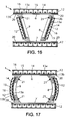
- FIGS. 16 and 17 are two schematic sectional views of the thermal flow management device according to the first embodiment of the invention installed on two geostationary satellites not having a generally parallelepiped shape.
- the vertical faces for example East 8 and West 9, are inclined relative to the vertical and symmetrically with respect to the central north-south axis.
- connection heat pipes 21 do not consist of two branches perpendicular to each other but of two non-perpendicular branches.
- the figure 18 is a perspective view of a third embodiment of the device according to the invention, and the figure 19 is a schematic sectional view of the third embodiment of the device according to the invention.
- the L-shaped connection heat pipes 21 are placed and fixed internally on the internal walls of the faces of the satellite 1.
- the device according to the invention remains identical to the devices as previously described, with the exception that the horizontal branch 22 of the connection heat pipes 21 is no longer placed on the extensions 20 of the North 6 and South 7 faces, but on the inner wall of the North 6 and South 7 faces in the internal space of the satellite 1 defined by its six faces.
- a heat-pipe loop is formed from the heat pipes present on the North 6 and South 7 faces in the radiative honeycomb panels 12 and making it possible to form a loop of heat pipes in thermal conduction contact.
- each other connecting the North and South faces to another pair of opposite faces of the satellite that is to say either the east / west face shield, or the pair of Earth / anti-Earth faces. Therefore, according to the invention, there is no internal structure for the satellite to allow the formation of this loop since the heat pipes are provided on the surface of the satellite faces.
- this loop By the formation of this loop, it is obtained a self-regulation of the dissipation of the heat emitted by the hot springs 19 provided on the North 6 and South 7 faces and distributed in the different heat pipes of this loop according to the rate of exposure of the different faces on which are fixed these heat pipes.
- the present invention applies preferentially to a spacecraft located in a geostationary orbit. Nevertheless, the principle of the invention remains the same for a spacecraft placed on any orbit around the Earth, for example highly elliptical orbits or HEO (high eccentricity orbit) or inclined orbits.
- HEO high eccentricity orbit
- the radiative panels 12 are fixed on the front face of the second vertical branches 23 of the connection heat pipes 21 provided on the faces East 8, West 9, Earth 5A and anti-Earth 5B, it is also possible to provide for the radiative panels 12 to be fixed on the rear face of the second vertical branches 23 of the connection heat pipes 21.
Landscapes
- Engineering & Computer Science (AREA)
- Life Sciences & Earth Sciences (AREA)
- Biodiversity & Conservation Biology (AREA)
- General Health & Medical Sciences (AREA)
- Aviation & Aerospace Engineering (AREA)
- Remote Sensing (AREA)
- Toxicology (AREA)
- Health & Medical Sciences (AREA)
- Environmental Sciences (AREA)
- Environmental & Geological Engineering (AREA)
- Sustainable Development (AREA)
- Thermal Sciences (AREA)
- General Engineering & Computer Science (AREA)
- Mechanical Engineering (AREA)
- Physics & Mathematics (AREA)
- Details Of Aerials (AREA)
- Cooling Or The Like Of Electrical Apparatus (AREA)
- Heat-Exchange Devices With Radiators And Conduit Assemblies (AREA)
- Automotive Seat Belt Assembly (AREA)
Claims (14)
- Raumfahrzeug, umfassend eine Vorrichtung zur Führung der Wärmeflüsse, wobei stets dieselbe Seite (5A) des Raumfahrzeugs (1) der Erde (4) zugewandt ist, wobei ein Paar entgegengesetzter zueinander parelleler Nord- (6) und Südseiten (7), welche senkrecht zu der Nord-Süd-Achse der Erde (4) sind, und zwei Paare zueinander paralleler entgegengesetzter Ost- (8)/Westseiten (9) und Erde- (5A)/Anti-Erdeseiten (5B), wobei wärmedissipierende oder -übertragende Vorrichtungen (19) an den Innenwänden (6a, 7a) der Nord- (6) und Südseiten (7) vorgesehen sind, dadurch gekennzeichnet, dass die Vorrichtung eine Mehrzahl von Wärmeleitern (13a, 13b, 13c, 21, 25a, 25b, 25c, 25d) umfasst, welche die Nord- (6) und Südseiten (7) des Fahrzeugs (1) mit einem anderen Paar entgegengesetzter Seiten (5A, 5B, 8, 9) des Fahrzeugs (1) verbinden und eine Wärmeleiter-Schlaufe (13a, 13b, 13c, 21, 25a, 25b, 25c, 25d) bilden, wobei die Wärmeleiter der Schlaufe miteinander in Wärmeleitungskontakt stehen.
- Raumfahrzeug nach Anspruch 1, dadurch gekennzeichnet, dass die Vorrichtung wenigstens ein Paar von Wärmeleitern zur Verbindung (21, 25a, 25b, 25c, 25d) mit einem ersten Zweig (22, 27a, 27b, 27c, 27d) und einem zweiten Zweig (23, 26a, 26b, 26c, 26d) umfasst, wobei der erste Zweig (22, 27a, 27b, 27c, 27d) von einem der Verbindungswärmeleiter (21, 25a, 25b, 25c, 25d) des Paars von Verbindungswärmeleitern (21, 25a, 25b, 25c, 25d) in Wärmeleitungskontakt an einem Strahlungspanel der Nordseite (6) befestigt ist und der erste Zweig (22, 27a, 27b, 27c, 27d) des anderen der Verbindungswärmeleiter (21, 25a, 25b, 25c, 25d) des Paars von Verbindungswärmeleitern (21, 25a, 25b, 25c, 25d) in Wärmeleitungskontakt an einem Strahlungspanel der Südseite (7) befestigt ist.
- Raumfahrzeug nach Anspruch 2, dadurch gekennzeichnet, dass der erste Zweig (22, 27a, 27b, 27c, 27d) des Verbindungswärmeleiters (21, 25a, 25b, 25c, 25d) an wenigstens einem Abschnitt einer Erstreckung (20) des Strahlungspanels entweder von der Nordseite (6) oder von der Südseite (7) von dem anderen Paar entgegengesetzter Seiten (5A, 5B, 8, 9) hervorstehend befestigt ist.
- Raumfahrzeug nach Anspruch 2, dadurch gekennzeichnet, dass der erste Zweig (22) des Verbindungswärmeleiters (21) an der Innenwand des Strahlungspanels entweder von der Nordseite (6) oder von der Südseite (7) in dem Innenvolumen befestigt ist, welches durch die Seiten (5A, 5B, 8, 9) des Raumfahrzeugs (1) begrenzt ist.
- Raumfahrzeug nach einem der Ansprüche 2 bis 4, dadurch gekennzeichnet, dass der zweite Zweig (23, 26a, 26c) des Verbindungswärmeleiters (21, 25a, 25b, 25c, 25d) an der Außenseite von einer der Seiten befestigt ist, welche zu dem anderen Paar entgegengesetzter Seiten (5A, 5B, 8, 9) gehört.
- Raumfahrzeug nach einem der Ansprüche 2 bis 5, dadurch gekennzeichnet, dass ein Strahlungspanel (12) an den zweiten Zweigen (23) des Paars von Verbindungswärmeleitern (21) befestigt ist.
- Raumfahrzeug nach einem der Ansprüche 2 bis 6, dadurch gekennzeichnet, dass die ersten (22) und zweiten (23) Zweige des Verbindungswärmeleiters (21) die gleiche Länge aufweisen.
- Raumfahrzeug nach einem der Ansprüche 2 bis 6, dadurch gekennzeichnet, dass der zweite Zweig (26b, 26d) des Verbindungswärmeleiters (25b, 25d) des Paars von Verbindungswärmeleitern (25a, 25b, 25c, 25d) in Wärmeleitungskontakt an einem anderen zweiten Zweig (26a, 26c) eines anderen Verbindungswärmeleiters (25a, 25c) des Paars von Verbindungswärmeleitern (25a, 25b, 25c, 25d) befestigt ist, der selbst an der Außenwand einer der Seiten befestigt ist, die zu dem anderen Paar entgegengesetzter Seiten (5A, 5B, 8, 9) gehören.
- Raumfahrzeug nach Anspruch 8, dadurch gekennzeichnet, dass der zweite Zweig (26a, 26b, 26c, 26d) des Verbindungswärmeleiters (25a, 25b, 25c, 25d) eine Länge aufweist, die größer ist als der erste Zweig (27a, 27b, 27c, 27d) des Verbindungswärmeleiters (25a, 25b, 25c, 25d).
- Raumfahrzeug nach Anspruch 8 oder 9, dadurch gekennzeichnet, dass eine Platte (29), vorzugsweise aus Aluminium, an den zweiten Zweigen (26b, 26d) der Verbindungswärmeleiter (25b, 25d) derselben Seite befestigt ist, die zu dem anderen Paar entgegengesetzter Seiten (5A, 5B, 8, 9) gehören und in Wärmeleitungskontakt mit einem zweiten Zweig (26a, 26c) eines anderen Verbindungswärmeleiters (25a, 25c) stehen.
- Raumfahrzeug nach Anspruch 8 oder 9, dadurch gekennzeichnet, dass der zweite Zweig (26b, 26d) des Verbindungswärmeleiters (25b, 25d), der an dem zweiten Zweig (26a, 26c) eines anderen Verbindungswärmeleiters (25a, 25c) befestigt ist, ein Paar von Flügeln (18a, 18b) tangential zu einem rohrartigen Element (17) umfasst, in welchem ein Kühlmittelfluid zirkuliert, wobei einer der Flügel (18a) größere transversale Ausmaße aufweist als der andere Flügel (18b).
- Raumfahrzeug nach einem der Ansprüche 1 bis 11, dadurch gekennzeichnet, dass an den Nord- (6) und Südseiten (7) wenigstens ein Strahlungspanel mit einer Struktur von Bienenwaben (12) vorgesehen ist, an oder in denen Wärmeleiternetze (13a, 13b, 13c) assoziiert sind.
- Raumfahrzeug nach Anspruch 12, dadurch gekennzeichnet, dass die Bienenwaben-Struktur (12) ein erstes Netz von Wärmeleitern (13a) umfasst, welche in Zellen (14) der Bienenwaben (12) aufgenommen sind, und ein zweites Netz von Wärmeleitern (13b), welche außen an einer Fläche der Bienenwaben (12) senkrecht zu den Wärmeleitern (13a) des ersten Netzes angeordnet sind.
- Raumfahrzeug nach Anspruch 12, dadurch gekennzeichnet, dass die Bienenwaben-Struktur (12) ein erstes Netz von Wärmeleitern (13a) umfasst, welche in Zellen (14) der Bienenwaben (12) aufgenommen sind, und ein zweites Netz von Wärmeleitern (13b), welche die Zellen (14) senkrecht zu den Wärmeleitern (13a) des ersten Netzes durchqueren.
Applications Claiming Priority (2)
| Application Number | Priority Date | Filing Date | Title |
|---|---|---|---|
| FR0608119A FR2905933B1 (fr) | 2006-09-15 | 2006-09-15 | Dispositif de gestion des flux thermiques dans un engin spatial et engin spatial equipe d'un tel dispositif |
| PCT/FR2007/051910 WO2008031985A1 (fr) | 2006-09-15 | 2007-09-11 | Dispositif de gestion des flux thermiques dans un engin spatial et engin spatial equipe d'un tel dispositif |
Publications (2)
| Publication Number | Publication Date |
|---|---|
| EP2069201A1 EP2069201A1 (de) | 2009-06-17 |
| EP2069201B1 true EP2069201B1 (de) | 2011-05-18 |
Family
ID=37907206
Family Applications (1)
| Application Number | Title | Priority Date | Filing Date |
|---|---|---|---|
| EP07823806A Active EP2069201B1 (de) | 2006-09-15 | 2007-09-11 | Vorrichtung zur steuerung des wärmeflusses in einem raumfahrzeug und mit derartiger vorrichtung ausgestattetes raumfahrzeug |
Country Status (6)
| Country | Link |
|---|---|
| US (1) | US8240612B2 (de) |
| EP (1) | EP2069201B1 (de) |
| AT (1) | ATE509831T1 (de) |
| ES (1) | ES2366149T3 (de) |
| FR (1) | FR2905933B1 (de) |
| WO (1) | WO2008031985A1 (de) |
Cited By (1)
| Publication number | Priority date | Publication date | Assignee | Title |
|---|---|---|---|---|
| RU2513325C1 (ru) * | 2012-10-02 | 2014-04-20 | Открытое акционерное общество "Информационные спутниковые системы" имени академика М.Ф. Решетнева" | Система терморегулирования космического аппарата |
Families Citing this family (32)
| Publication number | Priority date | Publication date | Assignee | Title |
|---|---|---|---|---|
| US8651172B2 (en) * | 2007-03-22 | 2014-02-18 | Raytheon Company | System and method for separating components of a fluid coolant for cooling a structure |
| US7921655B2 (en) * | 2007-09-21 | 2011-04-12 | Raytheon Company | Topping cycle for a sub-ambient cooling system |
| TR200706725A2 (tr) * | 2007-09-28 | 2009-04-21 | Terz�Akin Mehmet | Jiroskoplu mekanizma ile uzay aracı itiş sistemi |
| US7907409B2 (en) * | 2008-03-25 | 2011-03-15 | Raytheon Company | Systems and methods for cooling a computing component in a computing rack |
| US8820684B2 (en) * | 2009-03-24 | 2014-09-02 | Lockheed Martin Corporation | Spacecraft heat dissipation system |
| FR2960218B1 (fr) * | 2010-05-21 | 2012-08-03 | Thales Sa | Dispositif de dissipation thermique pour equipement spatial, notamment pour satellite |
| US20120097798A1 (en) * | 2010-10-25 | 2012-04-26 | Rust Sr John H | Inertial mass suspension |
| FR2975670B1 (fr) * | 2011-05-26 | 2016-01-15 | Astrium Sas | Piece de remplacement de reflecteur optique solaire pour satellite |
| US9352856B1 (en) * | 2013-12-04 | 2016-05-31 | Space Systems/Loral, Llc | Axially grooved crossing heat pipes |
| CN104317327B (zh) * | 2014-09-01 | 2017-12-08 | 深圳航天东方红海特卫星有限公司 | 一种构造整星热总线的均温装置 |
| US9376222B2 (en) | 2014-11-11 | 2016-06-28 | NovaWurks, Inc. | Method of cooling satlet electronics |
| FR3030458B1 (fr) * | 2014-12-18 | 2017-01-27 | Airbus Defence & Space Sas | Engin spatial |
| FR3031969B1 (fr) * | 2015-01-27 | 2017-01-27 | Airbus Defence & Space Sas | Satellite artificiel et procede de remplissage d'un reservoir de gaz propulsif dudit satellite artificiel |
| JP6448819B2 (ja) * | 2015-06-02 | 2019-01-09 | エアバス ディフェンス アンド スペース エスアーエス | 人工衛星 |
| US20170023306A1 (en) * | 2015-07-22 | 2017-01-26 | Compulab Ltd. | Layered heat pipe structure for cooling electronic component |
| FR3043764B1 (fr) | 2015-11-16 | 2018-01-05 | Airbus Defence And Space Sas | Dispositif d'echange thermique pour satellite artificiel, mur et assemblage de murs comprenant un tel dispositif d'echange thermique |
| WO2017169080A1 (ja) * | 2016-03-31 | 2017-10-05 | 三菱電機株式会社 | ヒートパイプパネルを用いた放熱装置 |
| US10368396B2 (en) | 2016-04-01 | 2019-07-30 | The Boeing Company | Heat pipe with printed heater and associated methods for manufacturing |
| FR3052443B1 (fr) * | 2016-06-10 | 2018-07-06 | Airbus Defence And Space Sas | Engin spatial |
| CN107914890A (zh) * | 2016-10-09 | 2018-04-17 | 海口未来技术研究院 | 临近空间飞行器用吊舱 |
| US20180162560A1 (en) | 2016-12-09 | 2018-06-14 | Space Systems/Loral, Llc | Enhanced radiator |
| US10591078B2 (en) | 2016-12-15 | 2020-03-17 | The Boeing Company | Fluid flow control device |
| CN106785218A (zh) * | 2017-01-19 | 2017-05-31 | 清华大学深圳研究生院 | 热管理结构及使用该热管理结构的无人机 |
| US10538346B2 (en) * | 2017-03-27 | 2020-01-21 | Space Systems/Loral, Llc | Electric thruster waste heat recovery during satellite orbit transfer |
| US11834205B1 (en) * | 2019-11-10 | 2023-12-05 | Space Exploration Technologies Corp. | Spacecraft chassis and component configuration |
| US12296989B1 (en) | 2021-02-23 | 2025-05-13 | Bae Systems Space & Mission Systems Inc. | Spacecraft thermal systems and methods |
| US12024318B1 (en) * | 2021-09-03 | 2024-07-02 | Blue Origin, Llc | Heat fins for heat dissipation of rocket components |
| US12630310B1 (en) | 2021-11-30 | 2026-05-19 | Bae Systems Space & Mission Systems Inc. | Heat spreader with integrated shock isolation |
| US20230322419A1 (en) * | 2022-04-11 | 2023-10-12 | Maxar Space Llc | Radiating coupling heat pipe |
| US12565338B1 (en) * | 2023-03-01 | 2026-03-03 | United States Of America As Represented By The Secretary Of The Air Force | Bidirectional regulating heat pipe network |
| CN117326099A (zh) * | 2023-10-08 | 2024-01-02 | 上海卫星工程研究所 | 中高轨卫星热区域缓冲方法 |
| CN119408743B (zh) * | 2025-01-03 | 2025-04-08 | 北京国电高科科技有限公司 | 应用于卫星的模块化散热装置和人造卫星 |
Family Cites Families (18)
| Publication number | Priority date | Publication date | Assignee | Title |
|---|---|---|---|---|
| US5344104A (en) * | 1992-09-21 | 1994-09-06 | General Electric Co. | Low cost, selectable configuration spacecraft |
| FR2700888B1 (fr) * | 1993-01-26 | 1995-04-07 | Matra Marconi Space France | Dispositif de refroidissement de tube à ondes progressives monté dans un satellite et satellite géostationnaire en comportant application. |
| US5474262A (en) * | 1994-02-08 | 1995-12-12 | Fairchild Space And Defense Corporation | Spacecraft structure and method |
| US5806803A (en) * | 1995-11-30 | 1998-09-15 | Hughes Electronics Corporation | Spacecraft radiator cooling system |
| US5806800A (en) * | 1995-12-22 | 1998-09-15 | Caplin; Glenn N. | Dual function deployable radiator cover |
| US5794890A (en) * | 1995-12-22 | 1998-08-18 | Hughes Electronics Corporation | Shielded radiator |
| US5735489A (en) * | 1995-12-22 | 1998-04-07 | Hughes Electronics | Heat transport system for spacecraft integration |
| US5823477A (en) * | 1995-12-22 | 1998-10-20 | Hughes Electronics Corporation | Device and method for minimizing radiator area required for heat dissipation on a spacecraft |
| GB9616016D0 (en) * | 1996-07-31 | 1996-09-11 | Matra Marconi Space Uk Ltd | Deployable radiators for spacecraft |
| US6003817A (en) * | 1996-11-12 | 1999-12-21 | Motorola, Inc. | Actively controlled thermal panel and method therefor |
| US6073887A (en) * | 1997-07-16 | 2000-06-13 | Space Systems/Loral, Inc. | High power spacecraft with full utilization of all spacecraft surfaces |
| US5957408A (en) * | 1997-12-05 | 1999-09-28 | Space Systems/Loral, Inc. | Satellite with east and west battery radiators |
| US6073888A (en) * | 1998-12-02 | 2000-06-13 | Loral Space & Communications, Ltd. | Sequenced heat rejection for body stabilized geosynchronous satellites |
| US6883588B1 (en) * | 2000-07-24 | 2005-04-26 | Space Systems/Loral, Inc. | Spacecraft radiator system using a heat pump |
| US6478258B1 (en) * | 2000-11-21 | 2002-11-12 | Space Systems/Loral, Inc. | Spacecraft multiple loop heat pipe thermal system for internal equipment panel applications |
| US20020139512A1 (en) * | 2001-03-30 | 2002-10-03 | Lenny Low | Spacecraft radiator system and method using east west coupled radiators |
| FR2853883B1 (fr) * | 2003-04-15 | 2006-01-27 | Cit Alcatel | Satellite comportant des moyens de transfert thermique d'une etagere supportant des equipements vers des panneaux radiateurs |
| US7143813B2 (en) * | 2004-07-28 | 2006-12-05 | The Boeing Company | Foam bumper and radiator for a lightweight heat rejection system |
-
2006
- 2006-09-15 FR FR0608119A patent/FR2905933B1/fr active Active
-
2007
- 2007-09-11 ES ES07823806T patent/ES2366149T3/es active Active
- 2007-09-11 WO PCT/FR2007/051910 patent/WO2008031985A1/fr not_active Ceased
- 2007-09-11 US US12/440,575 patent/US8240612B2/en active Active
- 2007-09-11 EP EP07823806A patent/EP2069201B1/de active Active
- 2007-09-11 AT AT07823806T patent/ATE509831T1/de not_active IP Right Cessation
Cited By (1)
| Publication number | Priority date | Publication date | Assignee | Title |
|---|---|---|---|---|
| RU2513325C1 (ru) * | 2012-10-02 | 2014-04-20 | Открытое акционерное общество "Информационные спутниковые системы" имени академика М.Ф. Решетнева" | Система терморегулирования космического аппарата |
Also Published As
| Publication number | Publication date |
|---|---|
| ES2366149T3 (es) | 2011-10-17 |
| US20100001141A1 (en) | 2010-01-07 |
| EP2069201A1 (de) | 2009-06-17 |
| ATE509831T1 (de) | 2011-06-15 |
| FR2905933B1 (fr) | 2008-12-26 |
| WO2008031985A1 (fr) | 2008-03-20 |
| US8240612B2 (en) | 2012-08-14 |
| FR2905933A1 (fr) | 2008-03-21 |
Similar Documents
| Publication | Publication Date | Title |
|---|---|---|
| WO2008031985A1 (fr) | Dispositif de gestion des flux thermiques dans un engin spatial et engin spatial equipe d'un tel dispositif | |
| EP2226248B1 (de) | Wärmekontrollvorrichtung für ein Raumfahrzeug | |
| EP1366990B1 (de) | Wärmetauschvorrichtung mit Verdampfer für Satellit | |
| EP1293428B1 (de) | Wärmetauscher | |
| EP1405790B1 (de) | Modulare Bauweise für die Wärmeregelung eines Raumfahrzeuges | |
| EP1468911A1 (de) | Satellit einschliesslich Mittel zum Wärmetransport von einem Vorrichtungsgestell zu Radiatorpaneelen | |
| FR3006298A1 (fr) | Vehicule spatial comprenant au moins un couple de bras porteurs muni d'un module creux de montage et procede pour la mise en oeuvre d'un tel vehicule | |
| EP0647559B1 (de) | Geostationärer Satellit mit elektrischen Akkumulatorenzellen | |
| FR2955379A1 (fr) | Systeme solaire thermique pour chauffer un espace habitable | |
| EP3347667A1 (de) | Wärmetauschvorrichtung für künstliche satelliten, wand und anordnung von wänden mit solch einer wärmetauschvorrichtung | |
| EP1199250B1 (de) | Verbesserungen an geostationären Satelliten | |
| EP2861928B1 (de) | Temperaturregelungsvorrichtung | |
| EP3445658B1 (de) | Raumfahrzeug | |
| FR3063806A1 (fr) | Dispositif de transfert thermique et engin spatial comportant un tel dispositif de transfert thermique | |
| FR2958448A1 (fr) | Dispositif de controle thermique d'un tube a collecteur rayonnant comportant un ecran, une boucle fluide et un radiateur a haute temperature | |
| EP2740161A2 (de) | Photovoltaisches modul mit einem wärmetauscher | |
| FR2951251A1 (fr) | Systeme de production d'energie combinant l'energie solaire thermique et l'energie photovoltaique | |
| EP3548830B1 (de) | Wärmetransporteinrichtung und raumfahrzeug mit einer solchen wärmetransporteinrichtung | |
| WO2003106264A1 (fr) | Dispositif de refroidissement pour vehicule spatial | |
| EP4599205A1 (de) | Unidirektionale zweiphasen-wärmeübertragungsstruktur | |
| EP2354712A1 (de) | Solarwärmekollektor, Solarwärmesystem, das einen solchen Solarwärmekollektor umfasst, und entsprechendes Heizverfahren eines Wohnraums | |
| EP3040284B1 (de) | Vorrichtung zur Rückgewinnung von Wärmeenergie, die von einem im Vakuum befindlichen Satelliten abgegeben wird |
Legal Events
| Date | Code | Title | Description |
|---|---|---|---|
| PUAI | Public reference made under article 153(3) epc to a published international application that has entered the european phase |
Free format text: ORIGINAL CODE: 0009012 |
|
| 17P | Request for examination filed |
Effective date: 20090302 |
|
| AK | Designated contracting states |
Kind code of ref document: A1 Designated state(s): AT BE BG CH CY CZ DE DK EE ES FI FR GB GR HU IE IS IT LI LT LU LV MC MT NL PL PT RO SE SI SK TR |
|
| AX | Request for extension of the european patent |
Extension state: AL BA HR MK RS |
|
| 17Q | First examination report despatched |
Effective date: 20090914 |
|
| GRAP | Despatch of communication of intention to grant a patent |
Free format text: ORIGINAL CODE: EPIDOSNIGR1 |
|
| DAX | Request for extension of the european patent (deleted) | ||
| GRAS | Grant fee paid |
Free format text: ORIGINAL CODE: EPIDOSNIGR3 |
|
| GRAA | (expected) grant |
Free format text: ORIGINAL CODE: 0009210 |
|
| REG | Reference to a national code |
Ref country code: GB Ref legal event code: FG4D Free format text: NOT ENGLISH |
|
| REG | Reference to a national code |
Ref country code: CH Ref legal event code: EP |
|
| REG | Reference to a national code |
Ref country code: IE Ref legal event code: FG4D Free format text: LANGUAGE OF EP DOCUMENT: FRENCH |
|
| REG | Reference to a national code |
Ref country code: DE Ref legal event code: R096 Ref document number: 602007014712 Country of ref document: DE Effective date: 20110630 |
|
| REG | Reference to a national code |
Ref country code: NL Ref legal event code: T3 |
|
| REG | Reference to a national code |
Ref country code: ES Ref legal event code: FG2A Ref document number: 2366149 Country of ref document: ES Kind code of ref document: T3 Effective date: 20111017 |
|
| PG25 | Lapsed in a contracting state [announced via postgrant information from national office to epo] |
Ref country code: LT Free format text: LAPSE BECAUSE OF FAILURE TO SUBMIT A TRANSLATION OF THE DESCRIPTION OR TO PAY THE FEE WITHIN THE PRESCRIBED TIME-LIMIT Effective date: 20110518 Ref country code: SE Free format text: LAPSE BECAUSE OF FAILURE TO SUBMIT A TRANSLATION OF THE DESCRIPTION OR TO PAY THE FEE WITHIN THE PRESCRIBED TIME-LIMIT Effective date: 20110518 Ref country code: PT Free format text: LAPSE BECAUSE OF FAILURE TO SUBMIT A TRANSLATION OF THE DESCRIPTION OR TO PAY THE FEE WITHIN THE PRESCRIBED TIME-LIMIT Effective date: 20110919 |
|
| PG25 | Lapsed in a contracting state [announced via postgrant information from national office to epo] |
Ref country code: SI Free format text: LAPSE BECAUSE OF FAILURE TO SUBMIT A TRANSLATION OF THE DESCRIPTION OR TO PAY THE FEE WITHIN THE PRESCRIBED TIME-LIMIT Effective date: 20110518 Ref country code: LV Free format text: LAPSE BECAUSE OF FAILURE TO SUBMIT A TRANSLATION OF THE DESCRIPTION OR TO PAY THE FEE WITHIN THE PRESCRIBED TIME-LIMIT Effective date: 20110518 Ref country code: FI Free format text: LAPSE BECAUSE OF FAILURE TO SUBMIT A TRANSLATION OF THE DESCRIPTION OR TO PAY THE FEE WITHIN THE PRESCRIBED TIME-LIMIT Effective date: 20110518 Ref country code: CY Free format text: LAPSE BECAUSE OF FAILURE TO SUBMIT A TRANSLATION OF THE DESCRIPTION OR TO PAY THE FEE WITHIN THE PRESCRIBED TIME-LIMIT Effective date: 20110518 Ref country code: AT Free format text: LAPSE BECAUSE OF FAILURE TO SUBMIT A TRANSLATION OF THE DESCRIPTION OR TO PAY THE FEE WITHIN THE PRESCRIBED TIME-LIMIT Effective date: 20110518 Ref country code: GR Free format text: LAPSE BECAUSE OF FAILURE TO SUBMIT A TRANSLATION OF THE DESCRIPTION OR TO PAY THE FEE WITHIN THE PRESCRIBED TIME-LIMIT Effective date: 20110819 Ref country code: IS Free format text: LAPSE BECAUSE OF FAILURE TO SUBMIT A TRANSLATION OF THE DESCRIPTION OR TO PAY THE FEE WITHIN THE PRESCRIBED TIME-LIMIT Effective date: 20110918 |
|
| REG | Reference to a national code |
Ref country code: IE Ref legal event code: FD4D |
|
| PG25 | Lapsed in a contracting state [announced via postgrant information from national office to epo] |
Ref country code: EE Free format text: LAPSE BECAUSE OF FAILURE TO SUBMIT A TRANSLATION OF THE DESCRIPTION OR TO PAY THE FEE WITHIN THE PRESCRIBED TIME-LIMIT Effective date: 20110518 Ref country code: CZ Free format text: LAPSE BECAUSE OF FAILURE TO SUBMIT A TRANSLATION OF THE DESCRIPTION OR TO PAY THE FEE WITHIN THE PRESCRIBED TIME-LIMIT Effective date: 20110518 Ref country code: IE Free format text: LAPSE BECAUSE OF FAILURE TO SUBMIT A TRANSLATION OF THE DESCRIPTION OR TO PAY THE FEE WITHIN THE PRESCRIBED TIME-LIMIT Effective date: 20110518 |
|
| PG25 | Lapsed in a contracting state [announced via postgrant information from national office to epo] |
Ref country code: SK Free format text: LAPSE BECAUSE OF FAILURE TO SUBMIT A TRANSLATION OF THE DESCRIPTION OR TO PAY THE FEE WITHIN THE PRESCRIBED TIME-LIMIT Effective date: 20110518 Ref country code: DK Free format text: LAPSE BECAUSE OF FAILURE TO SUBMIT A TRANSLATION OF THE DESCRIPTION OR TO PAY THE FEE WITHIN THE PRESCRIBED TIME-LIMIT Effective date: 20110518 Ref country code: RO Free format text: LAPSE BECAUSE OF FAILURE TO SUBMIT A TRANSLATION OF THE DESCRIPTION OR TO PAY THE FEE WITHIN THE PRESCRIBED TIME-LIMIT Effective date: 20110518 Ref country code: PL Free format text: LAPSE BECAUSE OF FAILURE TO SUBMIT A TRANSLATION OF THE DESCRIPTION OR TO PAY THE FEE WITHIN THE PRESCRIBED TIME-LIMIT Effective date: 20110518 |
|
| PLBE | No opposition filed within time limit |
Free format text: ORIGINAL CODE: 0009261 |
|
| STAA | Information on the status of an ep patent application or granted ep patent |
Free format text: STATUS: NO OPPOSITION FILED WITHIN TIME LIMIT |
|
| BERE | Be: lapsed |
Owner name: ASTRIUM SAS Effective date: 20110930 |
|
| 26N | No opposition filed |
Effective date: 20120221 |
|
| PG25 | Lapsed in a contracting state [announced via postgrant information from national office to epo] |
Ref country code: MC Free format text: LAPSE BECAUSE OF NON-PAYMENT OF DUE FEES Effective date: 20110930 |
|
| REG | Reference to a national code |
Ref country code: CH Ref legal event code: PL |
|
| REG | Reference to a national code |
Ref country code: DE Ref legal event code: R097 Ref document number: 602007014712 Country of ref document: DE Effective date: 20120221 |
|
| PG25 | Lapsed in a contracting state [announced via postgrant information from national office to epo] |
Ref country code: BE Free format text: LAPSE BECAUSE OF NON-PAYMENT OF DUE FEES Effective date: 20110930 |
|
| PG25 | Lapsed in a contracting state [announced via postgrant information from national office to epo] |
Ref country code: LI Free format text: LAPSE BECAUSE OF NON-PAYMENT OF DUE FEES Effective date: 20110930 Ref country code: CH Free format text: LAPSE BECAUSE OF NON-PAYMENT OF DUE FEES Effective date: 20110930 |
|
| PG25 | Lapsed in a contracting state [announced via postgrant information from national office to epo] |
Ref country code: MT Free format text: LAPSE BECAUSE OF FAILURE TO SUBMIT A TRANSLATION OF THE DESCRIPTION OR TO PAY THE FEE WITHIN THE PRESCRIBED TIME-LIMIT Effective date: 20110518 |
|
| PG25 | Lapsed in a contracting state [announced via postgrant information from national office to epo] |
Ref country code: BG Free format text: LAPSE BECAUSE OF FAILURE TO SUBMIT A TRANSLATION OF THE DESCRIPTION OR TO PAY THE FEE WITHIN THE PRESCRIBED TIME-LIMIT Effective date: 20110818 |
|
| PG25 | Lapsed in a contracting state [announced via postgrant information from national office to epo] |
Ref country code: TR Free format text: LAPSE BECAUSE OF FAILURE TO SUBMIT A TRANSLATION OF THE DESCRIPTION OR TO PAY THE FEE WITHIN THE PRESCRIBED TIME-LIMIT Effective date: 20110518 |
|
| PG25 | Lapsed in a contracting state [announced via postgrant information from national office to epo] |
Ref country code: HU Free format text: LAPSE BECAUSE OF FAILURE TO SUBMIT A TRANSLATION OF THE DESCRIPTION OR TO PAY THE FEE WITHIN THE PRESCRIBED TIME-LIMIT Effective date: 20110518 |
|
| REG | Reference to a national code |
Ref country code: FR Ref legal event code: PLFP Year of fee payment: 9 |
|
| REG | Reference to a national code |
Ref country code: FR Ref legal event code: PLFP Year of fee payment: 10 |
|
| REG | Reference to a national code |
Ref country code: FR Ref legal event code: PLFP Year of fee payment: 11 |
|
| REG | Reference to a national code |
Ref country code: FR Ref legal event code: PLFP Year of fee payment: 12 |
|
| PGFP | Annual fee paid to national office [announced via postgrant information from national office to epo] |
Ref country code: DE Payment date: 20250919 Year of fee payment: 19 |
|
| PGFP | Annual fee paid to national office [announced via postgrant information from national office to epo] |
Ref country code: NL Payment date: 20250918 Year of fee payment: 19 Ref country code: IT Payment date: 20250923 Year of fee payment: 19 Ref country code: LU Payment date: 20250919 Year of fee payment: 19 |
|
| PGFP | Annual fee paid to national office [announced via postgrant information from national office to epo] |
Ref country code: GB Payment date: 20250918 Year of fee payment: 19 |
|
| PGFP | Annual fee paid to national office [announced via postgrant information from national office to epo] |
Ref country code: FR Payment date: 20250919 Year of fee payment: 19 |
|
| PGFP | Annual fee paid to national office [announced via postgrant information from national office to epo] |
Ref country code: ES Payment date: 20251028 Year of fee payment: 19 |