EP2069566B1 - Dispositif et procédé de séchage de linge comprenant une pompe à chaleur et un échangeur thermique - Google Patents
Dispositif et procédé de séchage de linge comprenant une pompe à chaleur et un échangeur thermique Download PDFInfo
- Publication number
- EP2069566B1 EP2069566B1 EP07788476A EP07788476A EP2069566B1 EP 2069566 B1 EP2069566 B1 EP 2069566B1 EP 07788476 A EP07788476 A EP 07788476A EP 07788476 A EP07788476 A EP 07788476A EP 2069566 B1 EP2069566 B1 EP 2069566B1
- Authority
- EP
- European Patent Office
- Prior art keywords
- air flow
- channel
- heat pump
- process air
- heat exchanger
- Prior art date
- Legal status (The legal status is an assumption and is not a legal conclusion. Google has not performed a legal analysis and makes no representation as to the accuracy of the status listed.)
- Not-in-force
Links
Images

Classifications
-
- D—TEXTILES; PAPER
- D06—TREATMENT OF TEXTILES OR THE LIKE; LAUNDERING; FLEXIBLE MATERIALS NOT OTHERWISE PROVIDED FOR
- D06F—LAUNDERING, DRYING, IRONING, PRESSING OR FOLDING TEXTILE ARTICLES
- D06F58/00—Domestic laundry dryers
- D06F58/30—Drying processes
-
- D—TEXTILES; PAPER
- D06—TREATMENT OF TEXTILES OR THE LIKE; LAUNDERING; FLEXIBLE MATERIALS NOT OTHERWISE PROVIDED FOR
- D06F—LAUNDERING, DRYING, IRONING, PRESSING OR FOLDING TEXTILE ARTICLES
- D06F2103/00—Parameters monitored or detected for the control of domestic laundry washing machines, washer-dryers or laundry dryers
- D06F2103/50—Parameters monitored or detected for the control of domestic laundry washing machines, washer-dryers or laundry dryers related to heat pumps, e.g. pressure or flow rate
-
- D—TEXTILES; PAPER
- D06—TREATMENT OF TEXTILES OR THE LIKE; LAUNDERING; FLEXIBLE MATERIALS NOT OTHERWISE PROVIDED FOR
- D06F—LAUNDERING, DRYING, IRONING, PRESSING OR FOLDING TEXTILE ARTICLES
- D06F2105/00—Systems or parameters controlled or affected by the control systems of washing machines, washer-dryers or laundry dryers
- D06F2105/26—Heat pumps
-
- D—TEXTILES; PAPER
- D06—TREATMENT OF TEXTILES OR THE LIKE; LAUNDERING; FLEXIBLE MATERIALS NOT OTHERWISE PROVIDED FOR
- D06F—LAUNDERING, DRYING, IRONING, PRESSING OR FOLDING TEXTILE ARTICLES
- D06F2105/00—Systems or parameters controlled or affected by the control systems of washing machines, washer-dryers or laundry dryers
- D06F2105/28—Electric heating
-
- D—TEXTILES; PAPER
- D06—TREATMENT OF TEXTILES OR THE LIKE; LAUNDERING; FLEXIBLE MATERIALS NOT OTHERWISE PROVIDED FOR
- D06F—LAUNDERING, DRYING, IRONING, PRESSING OR FOLDING TEXTILE ARTICLES
- D06F58/00—Domestic laundry dryers
- D06F58/02—Domestic laundry dryers having dryer drums rotating about a horizontal axis
-
- D—TEXTILES; PAPER
- D06—TREATMENT OF TEXTILES OR THE LIKE; LAUNDERING; FLEXIBLE MATERIALS NOT OTHERWISE PROVIDED FOR
- D06F—LAUNDERING, DRYING, IRONING, PRESSING OR FOLDING TEXTILE ARTICLES
- D06F58/00—Domestic laundry dryers
- D06F58/20—General details of domestic laundry dryers
- D06F58/206—Heat pump arrangements
Definitions
- the invention relates to a device for drying laundry, comprising a substantially closed first channel system for guiding the process air acting on the laundry, in which first channel system, a treatment chamber for receiving the laundry, a first fan for driving the process air stream, a first cooling channel of a heat exchanger and a second heating channel of a heat pump are arranged, wherein the second heating channel along the process air flow is behind the first cooling channel, and an open second channel system for guiding a secondary air flow, in which second channel system a second fan for driving the secondary air flow, a first heating channel of the heat exchanger and a second cooling channel of the heat pump are arranged.
- the invention relates to a method for drying laundry, by means of a guided in a substantially closed first channel system and the laundry in a treatment chamber acting process air stream which cooled in a heat exchanger by a guided in an open second channel system secondary air flow and then by a heat pump Cooling of the secondary air flow is heated.
- thermoelectric heat pump on the one hand
- air-to-air heat exchanger on the other hand for the exchange of heat.
- a self-contained closed loop process air stream is heated in the heat pump and cooled in the heat exchanger
- a self-contained or open cooling air flow is cooled in the heat pump and heated in the heat exchanger.
- no further functional components are provided.
- a tumble dryer also results from each of the documents EP 0 477 554 B1 and EP 1 108 812 B1 , the disclosure of which is fully attributable to this disclosure.
- the duct system in which the air flow is guided is substantially closed - this means that the air flow circulates in the normal operation substantially without leaks, but does not assume a much higher pressure than air in the vicinity of the device.
- the treatment room for receiving the laundry is designed as a rotatable drum.
- a device for drying laundry emerges in which a heat pump is provided instead of the conventional arrangement of cooler and heater.
- a heat pump is provided instead of the conventional arrangement of cooler and heater.
- an evaporator takes the place of the cooler, and in place of the heater, a condenser for a circulating in an associated cycle of the heat pump working fluid.
- the channel system in which the air flow circulates can be brought into contact with the environment by opening a flap, in particular to discharge part of the air stream heated during operation from the device and to replace it with relatively cool ambient air ,
- a washing machine in which laundry not only washed, but also can be dried.
- an electric heating device for heating a used for drying laundry Air flow and a simple heat exchanger for cooling the heated air flow may be provided after applying the laundry, alternatively, a heat pump may be provided.
- This heat pump can be designed like the one in the EP 0 467 188 B1 It may also be a heat pump that uses Peltier elements to utilize the thermoelectric effect.
- a proper English short extract device for drying laundry which in turn corresponds to the type described input contains in its channel system in addition to a thermoelectric heat pump with cold and warm branch upstream of the cold branch additional heat exchanger for cooling the discharged air from the laundry and a warm Branch downstream additional heater for further heating of the air flow before applying the laundry.
- DE 35 09 549 A1 shows a device for drying laundry, which in addition to a heat pump has a further heating device and additional heat transport devices such as gravitation heat pipes.
- the input described apparatus and method according to EP 1 342 828 A2 have a disadvantage in that only the heat pump is available for heating the circulating process air flow. Also, the heat pump must pump the heat from its cooling channel to its heating channel via a significant temperature difference - at the outlet of the cooling channel prevails a temperature that is less than the temperature of the environment of the device is. With the corresponding cooling of the secondary air flow, it may optionally come to condensation of moisture in the secondary air flow, which may lead to a burden of the device with unwanted moisture and hygienic problems under certain circumstances.
- An object of the invention to be disclosed below is to provide the apparatus and method according to the EP 1 342 828 A2 be further developed so that an improved heating of the process air flow and a better operating point of the heat pump can be achieved.
- a device for drying laundry comprising a substantially closed first channel system for guiding a process air flow acting on the laundry, in which first channel system a treatment chamber for receiving the laundry, a first fan for driving the process air flow, a first Cooling channel of a heat exchanger and a second heating channel of a heat pump are disposed, wherein the second heating channel along the process air flow is behind the first cooling channel, and an open second channel system for guiding a secondary air flow, in which second channel system, a second fan for driving the secondary air flow, a first heating channel of the heat exchanger and a second cooling channel of the heat pump are arranged, and in which device in the first channel system, a heater for heating the process air stream is arranged, and the second cooling channel along the Seku the air flow is behind the first heating channel.
- a method for drying laundry is also carried out by means of a process air stream guided in a substantially closed first channel system and acting on the laundry in a treatment chamber, which is cooled in a heat exchanger by a secondary air flow guided in an open second channel system and thereafter is heated by a heat pump with cooling of the secondary air flow, in which method the process air flow is heated by a heater arranged in the first channel system and the cooling of the secondary air flow takes place behind the heat exchanger.
- the process air flow is heated not only by the heat pump, but also by a special heater, which according to conventional practice can be designed as an electrical resistance heater.
- the heat pump is inserted into the second channel system for the secondary air flow so that it does not cool the secondary air flow until it has absorbed heat from the process air flow in the heat exchanger and thus lost relative humidity. Therefore, the heat exchanging components of the heat pump are exposed to moisture exposure only to a small extent, resulting in a particularly low tendency to corrosion and, accordingly, an advantage of extended life.
- a sufficiently good efficiency of the heat exchanger assumed - the process air flow and the secondary air flow with a particularly low temperature difference in the corresponding channels heat pump, so that they can work at relatively low, averaged over their entire active volume temperature difference and thus particularly favorable conditions. This ensures a good efficiency of the heat pump.
- the heat introduced by the heater into the process air flow is no longer or less completely lost in the secondary air flow in the device according to the invention or in the method according to the invention, but is recovered with the heat pump and returned to the process air flow. Even if this recovery is not complete, but can be achieved by suitable design of the heater, the heat exchanger and the heat pump that the device meets the requirements of the known energy consumption class A.
- a preferred embodiment of the device is characterized in that the heater along the process air flow is arranged immediately in front of the treatment chamber. Such an undesirable loss of heat is kept low.
- the first fan along the process air flow is located immediately in front of the heater; so that the thermal load of the fan remains very small.
- the second fan is arranged along the secondary air flow in front of the first heating channel. This arrangement is particularly favorable for the construction of the device.
- first and second blowers should be noted that they have proven themselves in prior art devices, but are not necessarily mandatory for the functional success of the device according to the invention.
- Other arrangements for example, the first fan behind instead of in front of the drum or the second blower behind instead of before the first heating channel, are conceivable and, in particular depending on the arrangement of the components of the device in a conventional housing for a corresponding domestic appliance, also advantageous.
- the first channel system has a separator on the outlet side of the first cooling channel for separating moisture from the process air stream; This can be easily separated and disposed of in a simple and convenient way resulting in the heat exchanger condensate from the process air stream.
- the separator can be constructively connected to the heat exchanger according to current practice.
- separation of the condensate from the process air flow is an important criterion for achieving high efficiency, since in the process air flow remaining condensate must be evaporated again in the subsequent heating of the process air flow, which requires additional energy and thus the efficiency impaired the device during operation.
- the heater and the heat exchanger are set up for drying the laundry without using the heat pump.
- This development is favorable because it allows operation even without the heat pump as at least unusual component, albeit with some loss in terms of the energy to be used.
- the device thus achieves reliability as it would for a conventional clothes dryer is usual, without it depends on the characteristics of the heat pump used.
- the heater is designed for a maximum heating power of at most 2700 W, in particular about 2000 W.
- the heat exchanger has a cooling capacity of at least 1000 W, in particular about 1500 W.
- a particularly preferred development of the device has a heat pump with a thermoelectric pump unit.
- a pumping unit is very compact and simple, and therefore particularly suitable for use in a device designed as a tumble dryer.
- the particularly low load on the heat exchanging components has a particularly advantageous effect in such a heat pump, since in this case the problem of avoiding an impairment of the electrical components, the concept of the heat exchange components are immediately adjacent, to a much lesser extent than in such a heat pump in a device of the prior art.
- thermoelectric pumping unit to be used in accordance with the invention has a power consumption of about 500 W, the heater in the corresponding apparatus being arranged for optional operation at a high level with a power consumption of about 2000 W and at a low level with a power consumption of about 500 W, and wherein the heater and the pumping unit are arranged to control such that the pumping unit is operated in unison with the heater.
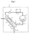
- the device 1 for drying laundry 2 according to FIG. 1 is a substantially closed first channel system 3, in which a process air stream 4 (symbolized by a straight arrow outside the channel system 3) circulates.
- a treatment chamber 5 in the form of a rotatable drum 5 is provided for receiving the laundry 2.
- the laundry 2 is introduced into the drum 5 and there acted upon by the process air stream 4.
- the process air stream 4 is driven by a first blower 6, which is part of the first duct system 3.
- a first heating channel 8 in the heat exchanger 7, 8 is acted upon by a secondary air flow 13 (likewise symbolized by a straight arrow) guided into an open second channel system 12, which is driven by a second fan 14.
- the secondary air stream 13 absorbs heat from the process air stream 4 in the heat exchanger 7, 8.
- a heat pump 9, 10, 11 comprising a second heating channel 9, in which the process air stream 4 passes, a second cooling channel 11, in which the secondary air flow 13 passes, and a pump unit 10, which internal heat exchanger of the heat pump 9, 10, 11, which are arranged in the channels 9 and 11 and heat or cool the flowing air flows, applied.
- process air stream 4 is reheated, by heat, which is taken according to the bent arrow the secondary air stream 13 in the second cooling channel 11, and in addition the waste heat, the is generated during operation of the heat pump 9, 10, 11.
- the process air stream 4 in the heat pump 9, 10, 11 is reheated. He then passes to the first fan 6 and from this to a conventional heater 15. There, it is further heated and finally returns to the treatment chamber 5.
- the secondary air stream 13 is taken from an environment of the device 1 and passes back into this environment, after he has passed through the second channel system 12.
- it is first heated by heat, which is taken from the process air stream 4.
- the secondary air stream 13 is cooled again, so that the heat that was taken from the process air stream 4 in the heat exchanger 7, 8, this at least partially re-flows.
- FIG. 2 shows a section of the in FIG. 1 recognizable device. Shown are the heat exchanger 7, 8, the heat pump 9, 10, 11 and a separator 16 for separating condensate, which has formed in the process air stream 4 after flowing through the first cooling channel 7.
- the heat pump 9, 10, 11 comprises two internal heat exchangers, which form the second heating channel 9 and the second cooling channel 11, and a pump unit 10, which contains a compressor and a throttle. Accordingly, the heat pump 9, 10, 11 a compressor heat pump, as it is known from a conventional refrigerator or freezer.
- thermoelectric heat pump 9, 10, 11 the pump unit 10 includes a circuit with Peltier elements, which are to be understood as special electronic components.
- a Peltier element has two poles between which a temperature difference arises when an electric current flows from one pole to the other pole.
- the integration of such Peltier elements in a pump unit 10 is basically known and requires this point no explanation.
Landscapes
- Engineering & Computer Science (AREA)
- Textile Engineering (AREA)
- Detail Structures Of Washing Machines And Dryers (AREA)
- Drying Of Solid Materials (AREA)
Claims (14)
- Dispositif (1) de séchage de linge (2), comprenant un premier système de canaux (3) essentiellement fermé, destiné à guider un flux d'air de procédé (4) alimentant le linge (2), dans lequel premier système de canaux (3) sont disposés une chambre de traitement (5) pour loger le linge (2), un premier ventilateur (6) pour entraîner le flux d'air de procédé (4), un premier canal de refroidissement (7) d'un échangeur de chaleur (7, 8) et un second canal de chauffage (9) d'une pompe à chaleur (9, 10, 11), le second canal de chauffage (9) étant situé le long du flux d'air de procédé (4) derrière le premier canal de refroidissement (7), ainsi qu'un second système de canaux (12) ouvert pour guider un flux d'air secondaire (13), dans lequel second système de canaux (12) sont disposés un second ventilateur (14) pour entraîner le flux d'air secondaire (13), un premier canal de chauffage (8) de l'échangeur de chaleur (7, 8) et un second canal de refroidissement (11) de la pompe à chaleur (9, 10, 11), un dispositif de chauffage (15) étant disposé dans le premier système de canaux (3) pour chauffer le flux d'air de procédé (4), caractérisé en ce que le second canal de refroidissement (11) est situé le long du flux d'air secondaire (13) derrière le premier canal de chauffage (8).
- Dispositif (1) selon la revendication 1, dans lequel le dispositif de chauffage (15) est disposé le long du flux d'air de procédé (4) directement devant la chambre de traitement (5).
- Dispositif (1) selon la revendication 2, dans lequel le premier ventilateur (6) est disposé le long du flux d'air de procédé (4) directement devant le dispositif de chauffage (15).
- Dispositif (1) selon l'une quelconque des revendications précédentes, dans lequel le second ventilateur (14) est disposé le long du flux d'air secondaire (13) devant le premier canal de chauffage (8).
- Dispositif (1) selon l'une quelconque des revendications précédentes, dans lequel le premier système de canaux (3) présente, en aval du premier canal de refroidissement (7), un séparateur (16) destiné à séparer l'humidité du flux d'air de procédé (4).
- Dispositif (1) selon la revendication 1, dans lequel la chambre de traitement (5) est rotative et est notamment réalisée en tant que tambour (5).
- Dispositif (1) selon l'une quelconque des revendications précédentes, dans lequel le dispositif de chauffage (15) et l'échangeur de chaleur (7, 8) sont agencés pour le séchage du linge (2) sans utiliser la pompe à chaleur (9, 10, 11).
- Dispositif (1) selon l'une quelconque des revendications précédentes, dans lequel le dispositif de chauffage (15) est conçu pour une puissance de chauffage maximale de maximum 2700 W, notamment d'environ 2000 W.
- Dispositif (1) selon l'une quelconque des revendications précédentes, dans lequel l'échangeur de chaleur (7, 8) a une puissance de refroidissement d'au moins 1000 W, notamment d'environ 1500 W.
- Dispositif (1) selon l'une quelconque des revendications précédentes, dans lequel la pompe à chaleur (9, 10, 11) a une puissance absorbée comprise entre 200 W et 800 W, notamment d'environ 500 W.
- Dispositif (1) selon l'une quelconque des revendications précédentes, dans lequel la pompe à chaleur (9, 10, 11) présente une unité de pompe thermoélectrique (10).
- Dispositif (1) selon la revendication 11, dans lequel l'unité de pompe (10) a une puissance absorbée d'environ 500 W, et dans lequel le dispositif de chauffage (15) est agencé pour le fonctionnement au choix sur un échelon élevé avec une puissance absorbée d'environ 2000 W et sur un échelon faible avec une puissance absorbée d'environ 500 W, le dispositif de chauffage (15) et l'unité de pompe (10) étant agencés pour la commande de manière à ce que l'unité de pompe (10) fonctionne en commun avec le dispositif de chauffage (15).
- Procédé de séchage de linge (2) au moyen d'un flux d'air de procédé (4) guidé dans un premier système de canaux (3) essentiellement fermé et alimentant le linge (2) se trouvant dans une chambre de traitement (5), lequel flux d'air de procédé est refroidi dans un échangeur de chaleur (7, 8) au moyen d'un flux d'air secondaire (13) guidé dans un second système de canaux ouvert (12) et est ensuite chauffé par une pompe à chaleur (9, 10, 11) par refroidissement du flux d'air secondaire (13), le flux d'air de procédé (4) étant chauffé par un dispositif de chauffage (15) disposé dans le premier système de canaux (3), caractérisé en ce que le refroidissement du flux d'air secondaire (13) est réalisé derrière l'échangeur de chaleur (7, 8).
- Procédé selon la revendication 13, dans lequel la pompe à chaleur (9, 10, 11) fonctionne en même temps que le dispositif de chauffage (15).
Applications Claiming Priority (2)
| Application Number | Priority Date | Filing Date | Title |
|---|---|---|---|
| DE102006042991A DE102006042991A1 (de) | 2006-09-13 | 2006-09-13 | Vorrichtung und Verfahren zum Trocknen von Waschgut mit einer Wärmepumpe und einem Wärmetauscher |
| PCT/EP2007/058562 WO2008031688A1 (fr) | 2006-09-13 | 2007-08-17 | Dispositif et procédé de séchage de linge comprenant une pompe à chaleur et un échangeur thermique |
Publications (2)
| Publication Number | Publication Date |
|---|---|
| EP2069566A1 EP2069566A1 (fr) | 2009-06-17 |
| EP2069566B1 true EP2069566B1 (fr) | 2010-04-07 |
Family
ID=38722784
Family Applications (1)
| Application Number | Title | Priority Date | Filing Date |
|---|---|---|---|
| EP07788476A Not-in-force EP2069566B1 (fr) | 2006-09-13 | 2007-08-17 | Dispositif et procédé de séchage de linge comprenant une pompe à chaleur et un échangeur thermique |
Country Status (5)
| Country | Link |
|---|---|
| US (1) | US20100083524A1 (fr) |
| EP (1) | EP2069566B1 (fr) |
| AT (1) | ATE463608T1 (fr) |
| DE (2) | DE102006042991A1 (fr) |
| WO (1) | WO2008031688A1 (fr) |
Families Citing this family (12)
| Publication number | Priority date | Publication date | Assignee | Title |
|---|---|---|---|---|
| DE102006026251A1 (de) * | 2006-06-06 | 2007-12-13 | BSH Bosch und Siemens Hausgeräte GmbH | Vorrichtung und Verfahren zum Trocknen von Waschgut |
| DE102008044277A1 (de) * | 2008-12-02 | 2010-06-10 | BSH Bosch und Siemens Hausgeräte GmbH | Trockner mit einer Wärmepumpe und einer elektrischen Heizung sowie Verfahren zu seinem Betrieb |
| ES2414408T3 (es) * | 2009-06-29 | 2013-07-19 | Arçelik Anonim Sirketi | Secadora de ropa cuya eficacia de secado se incrementa mediante el uso de diferentes fuentes de calor |
| EP2372012B1 (fr) * | 2010-03-30 | 2016-08-31 | DBK David + Baader GmbH | Unité de condensateur, appareil domestique, et procédé de contrôle de cet appareil domestique |
| DE102010043455A1 (de) * | 2010-11-05 | 2012-05-10 | BSH Bosch und Siemens Hausgeräte GmbH | Trocknungseinrichtung und Hausgerät mit einer solchen Trocknungseinrichtung |
| ITRN20110055A1 (it) * | 2011-08-05 | 2013-02-06 | Indesit Co Spa | Elettrodomestico |
| EP2631351A1 (fr) | 2012-02-23 | 2013-08-28 | Electrolux Home Products Corporation N.V. | Séchoir à linge |
| EP2796613B1 (fr) * | 2013-04-23 | 2020-11-11 | Whirlpool Corporation | Sèche-linge ou lave-linge sèche-linge et procédé pour son fonctionnement |
| KR102364673B1 (ko) | 2014-10-28 | 2022-02-18 | 엘지전자 주식회사 | 의류처리장치 및 그 제어방법 |
| EP3257425B1 (fr) * | 2015-02-12 | 2020-09-16 | Foshan Shunde Midea Washing Appliances Mfg. Co., Ltd. | Machine à laver la vaisselle |
| DE102016214753A1 (de) * | 2016-08-09 | 2018-02-15 | BSH Hausgeräte GmbH | Wäschebehandlungsgerät |
| TR201721922A2 (tr) | 2017-12-26 | 2019-07-22 | Arcelik As | Kurutmali çamaşir maki̇neleri̇nde isi pompasi si̇stemi̇ |
Family Cites Families (8)
| Publication number | Priority date | Publication date | Assignee | Title |
|---|---|---|---|---|
| DE2914859C2 (de) * | 1979-04-12 | 1986-11-06 | Bauknecht Hausgeräte GmbH, 7000 Stuttgart | Wäschetrockner |
| DE3113471A1 (de) * | 1981-04-03 | 1982-10-21 | Licentia Patent-Verwaltungs-Gmbh, 6000 Frankfurt | Trockengeraet mit waermepumpe |
| DE4330456C1 (de) * | 1993-09-08 | 1995-03-16 | Blomberg Werke Gmbh | Wäschetrockner |
| DE4434205A1 (de) * | 1994-08-31 | 1996-03-07 | Joerg Sdrojewski | Wäschetrockner |
| DE19731826A1 (de) * | 1997-07-24 | 1998-02-12 | Joachim Rieder | Wäschetrockner mit kontinuierlicher Wärmerückgewinnung |
| DE20101641U1 (de) * | 2001-01-29 | 2002-06-06 | AKG-Thermotechnik GmbH & Co. KG, 34369 Hofgeismar | Kondensations-Wäschetrockner und dafür geeigneter Kondensations-Wärmeaustauscher |
| DE20202782U1 (de) * | 2002-02-21 | 2002-04-25 | Blum, Theodor, 79241 Ihringen | Wäschetrockner |
| KR100504503B1 (ko) * | 2003-01-14 | 2005-08-01 | 엘지전자 주식회사 | 공기조화시스템 |
-
2006
- 2006-09-13 DE DE102006042991A patent/DE102006042991A1/de not_active Withdrawn
-
2007
- 2007-08-17 DE DE502007003423T patent/DE502007003423D1/de active Active
- 2007-08-17 EP EP07788476A patent/EP2069566B1/fr not_active Not-in-force
- 2007-08-17 WO PCT/EP2007/058562 patent/WO2008031688A1/fr not_active Ceased
- 2007-08-17 US US12/310,953 patent/US20100083524A1/en not_active Abandoned
- 2007-08-17 AT AT07788476T patent/ATE463608T1/de active
Also Published As
| Publication number | Publication date |
|---|---|
| ATE463608T1 (de) | 2010-04-15 |
| DE102006042991A1 (de) | 2008-03-27 |
| US20100083524A1 (en) | 2010-04-08 |
| DE502007003423D1 (de) | 2010-05-20 |
| WO2008031688A1 (fr) | 2008-03-20 |
| EP2069566A1 (fr) | 2009-06-17 |
Similar Documents
| Publication | Publication Date | Title |
|---|---|---|
| EP2069566B1 (fr) | Dispositif et procédé de séchage de linge comprenant une pompe à chaleur et un échangeur thermique | |
| EP2029804B1 (fr) | Dispositif et procédé de séchage de linge | |
| EP2115208B1 (fr) | Sèche-linge à condensation équipé d'une pompe à chaleur et procédé pour faire fonctionner ce sèche-linge | |
| DE102006061737B3 (de) | Kondensationstrockner mit einer Wärmepumpe sowie Verfahren zu seinem Betrieb | |
| DE102013111491B4 (de) | Bekleidungstrockner und Betriebsverfahren eines Bekleidungstrockners | |
| EP1960586B1 (fr) | Dispositif et procede pour appliquer un ecoulement d'air sur du linge a laver | |
| EP2058428B1 (fr) | Séchoir doté d'une pompe à chaleur | |
| DE102007057766A1 (de) | Ablufttrockner mit einer Wärmepumpe und einem ersten Gebläse | |
| DE102008007971A1 (de) | Kondensationstrockner mit Wärmepumpe und Heizung sowie Verfahren zu seinem Betrieb | |
| DE60219112T2 (de) | Verfahren und Vorrichtung zur Trocknung mittels Luftzirkulation | |
| DE102014219457B4 (de) | Trockner mit einer Wärmepumpe und einer Zusatzheizung sowie Verfahren zu seinem Betrieb | |
| WO2008110449A1 (fr) | Séchoir à récupération de chaleur et procédé de fonctionnement | |
| EP2075369A2 (fr) | Sèche-linge équipé de manière à fonctionner en recevant une puissance électrique et son procédé de fonctionnement | |
| EP2140061A2 (fr) | Sèche-linge à condensation et procédé permettant de faire fonctionner un sèche-linge à condensation | |
| DE102014118793A1 (de) | Vorrichtung und Verfahren zum Erhitzen einer Behandlungsflüssigkeit für ein Wäschebehandlungsgerät und Wäschebehandlungsgerät | |
| DE10022613C2 (de) | Kondensations-Wäschetrockner mit Wärmepumpe und Zusatz-Widerstandsheizung | |
| CH705546A2 (de) | Wäschetrockner mit Zusatzheizung und Zusatzwärmetauscher. | |
| EP2744936A1 (fr) | Appareil sèche-linge muni d'une pompe à chaleur comprenant un moteur et son procédé de fonctionnement | |
| DE69910526T2 (de) | Trommeltrockner mit einer Wärmepumpe | |
| DE3543722A1 (de) | Waeschetrockner | |
| DE102010028441A1 (de) | Waschtrockner mit einer Wärmepumpe und Verfahren zu seinem Betrieb | |
| EP1969171B1 (fr) | Installation de pompe a chaleur, en particulier pour appareil menager | |
| DE102014118791A1 (de) | Vorrichtung und Verfahren zum Bereitstellen von Heizleistung für ein Wäschebehandlungsgerät und Wäschebehandlungsgerät | |
| DE102005060673A1 (de) | Wäschetrockner mit Peltier-Wärmepumpe | |
| WO2009083345A1 (fr) | Sécheur avec un circuit de pompe à chaleur |
Legal Events
| Date | Code | Title | Description |
|---|---|---|---|
| PUAI | Public reference made under article 153(3) epc to a published international application that has entered the european phase |
Free format text: ORIGINAL CODE: 0009012 |
|
| 17P | Request for examination filed |
Effective date: 20090414 |
|
| AK | Designated contracting states |
Kind code of ref document: A1 Designated state(s): AT BE BG CH CY CZ DE DK EE ES FI FR GB GR HU IE IS IT LI LT LU LV MC MT NL PL PT RO SE SI SK TR |
|
| AX | Request for extension of the european patent |
Extension state: AL BA HR MK RS |
|
| RIN1 | Information on inventor provided before grant (corrected) |
Inventor name: MUELLER, MARKUS Inventor name: PAATZSCH, RENE |
|
| GRAP | Despatch of communication of intention to grant a patent |
Free format text: ORIGINAL CODE: EPIDOSNIGR1 |
|
| GRAS | Grant fee paid |
Free format text: ORIGINAL CODE: EPIDOSNIGR3 |
|
| GRAA | (expected) grant |
Free format text: ORIGINAL CODE: 0009210 |
|
| AK | Designated contracting states |
Kind code of ref document: B1 Designated state(s): AT BE BG CH CY CZ DE DK EE ES FI FR GB GR HU IE IS IT LI LT LU LV MC MT NL PL PT RO SE SI SK TR |
|
| REG | Reference to a national code |
Ref country code: GB Ref legal event code: FG4D Free format text: NOT ENGLISH |
|
| REG | Reference to a national code |
Ref country code: CH Ref legal event code: EP |
|
| REG | Reference to a national code |
Ref country code: IE Ref legal event code: FG4D Free format text: LANGUAGE OF EP DOCUMENT: GERMAN |
|
| REF | Corresponds to: |
Ref document number: 502007003423 Country of ref document: DE Date of ref document: 20100520 Kind code of ref document: P |
|
| REG | Reference to a national code |
Ref country code: NL Ref legal event code: VDEP Effective date: 20100407 |
|
| PG25 | Lapsed in a contracting state [announced via postgrant information from national office to epo] |
Ref country code: SI Free format text: LAPSE BECAUSE OF FAILURE TO SUBMIT A TRANSLATION OF THE DESCRIPTION OR TO PAY THE FEE WITHIN THE PRESCRIBED TIME-LIMIT Effective date: 20100407 |
|
| LTIE | Lt: invalidation of european patent or patent extension |
Effective date: 20100407 |
|
| REG | Reference to a national code |
Ref country code: IE Ref legal event code: FD4D |
|
| PG25 | Lapsed in a contracting state [announced via postgrant information from national office to epo] |
Ref country code: LT Free format text: LAPSE BECAUSE OF FAILURE TO SUBMIT A TRANSLATION OF THE DESCRIPTION OR TO PAY THE FEE WITHIN THE PRESCRIBED TIME-LIMIT Effective date: 20100407 Ref country code: SE Free format text: LAPSE BECAUSE OF FAILURE TO SUBMIT A TRANSLATION OF THE DESCRIPTION OR TO PAY THE FEE WITHIN THE PRESCRIBED TIME-LIMIT Effective date: 20100407 Ref country code: NL Free format text: LAPSE BECAUSE OF FAILURE TO SUBMIT A TRANSLATION OF THE DESCRIPTION OR TO PAY THE FEE WITHIN THE PRESCRIBED TIME-LIMIT Effective date: 20100407 Ref country code: ES Free format text: LAPSE BECAUSE OF FAILURE TO SUBMIT A TRANSLATION OF THE DESCRIPTION OR TO PAY THE FEE WITHIN THE PRESCRIBED TIME-LIMIT Effective date: 20100718 |
|
| PG25 | Lapsed in a contracting state [announced via postgrant information from national office to epo] |
Ref country code: FI Free format text: LAPSE BECAUSE OF FAILURE TO SUBMIT A TRANSLATION OF THE DESCRIPTION OR TO PAY THE FEE WITHIN THE PRESCRIBED TIME-LIMIT Effective date: 20100407 Ref country code: IS Free format text: LAPSE BECAUSE OF FAILURE TO SUBMIT A TRANSLATION OF THE DESCRIPTION OR TO PAY THE FEE WITHIN THE PRESCRIBED TIME-LIMIT Effective date: 20100807 Ref country code: LV Free format text: LAPSE BECAUSE OF FAILURE TO SUBMIT A TRANSLATION OF THE DESCRIPTION OR TO PAY THE FEE WITHIN THE PRESCRIBED TIME-LIMIT Effective date: 20100407 |
|
| PG25 | Lapsed in a contracting state [announced via postgrant information from national office to epo] |
Ref country code: PL Free format text: LAPSE BECAUSE OF FAILURE TO SUBMIT A TRANSLATION OF THE DESCRIPTION OR TO PAY THE FEE WITHIN THE PRESCRIBED TIME-LIMIT Effective date: 20100407 Ref country code: CY Free format text: LAPSE BECAUSE OF FAILURE TO SUBMIT A TRANSLATION OF THE DESCRIPTION OR TO PAY THE FEE WITHIN THE PRESCRIBED TIME-LIMIT Effective date: 20100609 |
|
| PG25 | Lapsed in a contracting state [announced via postgrant information from national office to epo] |
Ref country code: IE Free format text: LAPSE BECAUSE OF FAILURE TO SUBMIT A TRANSLATION OF THE DESCRIPTION OR TO PAY THE FEE WITHIN THE PRESCRIBED TIME-LIMIT Effective date: 20100407 Ref country code: EE Free format text: LAPSE BECAUSE OF FAILURE TO SUBMIT A TRANSLATION OF THE DESCRIPTION OR TO PAY THE FEE WITHIN THE PRESCRIBED TIME-LIMIT Effective date: 20100407 Ref country code: DK Free format text: LAPSE BECAUSE OF FAILURE TO SUBMIT A TRANSLATION OF THE DESCRIPTION OR TO PAY THE FEE WITHIN THE PRESCRIBED TIME-LIMIT Effective date: 20100407 Ref country code: PT Free format text: LAPSE BECAUSE OF FAILURE TO SUBMIT A TRANSLATION OF THE DESCRIPTION OR TO PAY THE FEE WITHIN THE PRESCRIBED TIME-LIMIT Effective date: 20100809 |
|
| PLBE | No opposition filed within time limit |
Free format text: ORIGINAL CODE: 0009261 |
|
| STAA | Information on the status of an ep patent application or granted ep patent |
Free format text: STATUS: NO OPPOSITION FILED WITHIN TIME LIMIT |
|
| BERE | Be: lapsed |
Owner name: BSH BOSCH UND SIEMENS HAUSGERATE G.M.B.H. Effective date: 20100831 |
|
| PG25 | Lapsed in a contracting state [announced via postgrant information from national office to epo] |
Ref country code: SK Free format text: LAPSE BECAUSE OF FAILURE TO SUBMIT A TRANSLATION OF THE DESCRIPTION OR TO PAY THE FEE WITHIN THE PRESCRIBED TIME-LIMIT Effective date: 20100407 Ref country code: RO Free format text: LAPSE BECAUSE OF FAILURE TO SUBMIT A TRANSLATION OF THE DESCRIPTION OR TO PAY THE FEE WITHIN THE PRESCRIBED TIME-LIMIT Effective date: 20100407 Ref country code: CZ Free format text: LAPSE BECAUSE OF FAILURE TO SUBMIT A TRANSLATION OF THE DESCRIPTION OR TO PAY THE FEE WITHIN THE PRESCRIBED TIME-LIMIT Effective date: 20100407 |
|
| 26N | No opposition filed |
Effective date: 20110110 |
|
| PG25 | Lapsed in a contracting state [announced via postgrant information from national office to epo] |
Ref country code: MC Free format text: LAPSE BECAUSE OF NON-PAYMENT OF DUE FEES Effective date: 20100831 |
|
| PG25 | Lapsed in a contracting state [announced via postgrant information from national office to epo] |
Ref country code: GR Free format text: LAPSE BECAUSE OF FAILURE TO SUBMIT A TRANSLATION OF THE DESCRIPTION OR TO PAY THE FEE WITHIN THE PRESCRIBED TIME-LIMIT Effective date: 20100708 |
|
| PG25 | Lapsed in a contracting state [announced via postgrant information from national office to epo] |
Ref country code: BE Free format text: LAPSE BECAUSE OF NON-PAYMENT OF DUE FEES Effective date: 20100831 |
|
| PG25 | Lapsed in a contracting state [announced via postgrant information from national office to epo] |
Ref country code: MT Free format text: LAPSE BECAUSE OF FAILURE TO SUBMIT A TRANSLATION OF THE DESCRIPTION OR TO PAY THE FEE WITHIN THE PRESCRIBED TIME-LIMIT Effective date: 20100407 |
|
| REG | Reference to a national code |
Ref country code: CH Ref legal event code: PL |
|
| PG25 | Lapsed in a contracting state [announced via postgrant information from national office to epo] |
Ref country code: LI Free format text: LAPSE BECAUSE OF NON-PAYMENT OF DUE FEES Effective date: 20110831 Ref country code: CH Free format text: LAPSE BECAUSE OF NON-PAYMENT OF DUE FEES Effective date: 20110831 |
|
| PG25 | Lapsed in a contracting state [announced via postgrant information from national office to epo] |
Ref country code: LU Free format text: LAPSE BECAUSE OF NON-PAYMENT OF DUE FEES Effective date: 20100817 Ref country code: BG Free format text: LAPSE BECAUSE OF FAILURE TO SUBMIT A TRANSLATION OF THE DESCRIPTION OR TO PAY THE FEE WITHIN THE PRESCRIBED TIME-LIMIT Effective date: 20100407 Ref country code: HU Free format text: LAPSE BECAUSE OF FAILURE TO SUBMIT A TRANSLATION OF THE DESCRIPTION OR TO PAY THE FEE WITHIN THE PRESCRIBED TIME-LIMIT Effective date: 20101008 |
|
| PG25 | Lapsed in a contracting state [announced via postgrant information from national office to epo] |
Ref country code: TR Free format text: LAPSE BECAUSE OF FAILURE TO SUBMIT A TRANSLATION OF THE DESCRIPTION OR TO PAY THE FEE WITHIN THE PRESCRIBED TIME-LIMIT Effective date: 20100407 |
|
| PGFP | Annual fee paid to national office [announced via postgrant information from national office to epo] |
Ref country code: IT Payment date: 20120828 Year of fee payment: 6 Ref country code: FR Payment date: 20120831 Year of fee payment: 6 |
|
| PG25 | Lapsed in a contracting state [announced via postgrant information from national office to epo] |
Ref country code: BG Free format text: LAPSE BECAUSE OF FAILURE TO SUBMIT A TRANSLATION OF THE DESCRIPTION OR TO PAY THE FEE WITHIN THE PRESCRIBED TIME-LIMIT Effective date: 20100707 |
|
| REG | Reference to a national code |
Ref country code: AT Ref legal event code: MM01 Ref document number: 463608 Country of ref document: AT Kind code of ref document: T Effective date: 20120831 |
|
| PG25 | Lapsed in a contracting state [announced via postgrant information from national office to epo] |
Ref country code: AT Free format text: LAPSE BECAUSE OF NON-PAYMENT OF DUE FEES Effective date: 20120831 |
|
| REG | Reference to a national code |
Ref country code: FR Ref legal event code: ST Effective date: 20140430 |
|
| PG25 | Lapsed in a contracting state [announced via postgrant information from national office to epo] |
Ref country code: IT Free format text: LAPSE BECAUSE OF NON-PAYMENT OF DUE FEES Effective date: 20130817 |
|
| PG25 | Lapsed in a contracting state [announced via postgrant information from national office to epo] |
Ref country code: FR Free format text: LAPSE BECAUSE OF NON-PAYMENT OF DUE FEES Effective date: 20130902 |
|
| REG | Reference to a national code |
Ref country code: DE Ref legal event code: R081 Ref document number: 502007003423 Country of ref document: DE Owner name: BSH HAUSGERAETE GMBH, DE Free format text: FORMER OWNER: BSH BOSCH UND SIEMENS HAUSGERAETE GMBH, 81739 MUENCHEN, DE Effective date: 20150408 |
|
| REG | Reference to a national code |
Ref country code: DE Ref legal event code: R084 Ref document number: 502007003423 Country of ref document: DE |
|
| PGFP | Annual fee paid to national office [announced via postgrant information from national office to epo] |
Ref country code: GB Payment date: 20230824 Year of fee payment: 17 |
|
| PGFP | Annual fee paid to national office [announced via postgrant information from national office to epo] |
Ref country code: DE Payment date: 20230831 Year of fee payment: 17 |
|
| REG | Reference to a national code |
Ref country code: DE Ref legal event code: R119 Ref document number: 502007003423 Country of ref document: DE |
|
| GBPC | Gb: european patent ceased through non-payment of renewal fee |
Effective date: 20240817 |
|
| PG25 | Lapsed in a contracting state [announced via postgrant information from national office to epo] |
Ref country code: DE Free format text: LAPSE BECAUSE OF NON-PAYMENT OF DUE FEES Effective date: 20250301 |
|
| PG25 | Lapsed in a contracting state [announced via postgrant information from national office to epo] |
Ref country code: GB Free format text: LAPSE BECAUSE OF NON-PAYMENT OF DUE FEES Effective date: 20240817 |