EP2069678B1 - Verfahren und vorrichtung für einen vereinfachten und hygienischen zugang zu einer fluidkammer - Google Patents
Verfahren und vorrichtung für einen vereinfachten und hygienischen zugang zu einer fluidkammer Download PDFInfo
- Publication number
- EP2069678B1 EP2069678B1 EP07766279A EP07766279A EP2069678B1 EP 2069678 B1 EP2069678 B1 EP 2069678B1 EP 07766279 A EP07766279 A EP 07766279A EP 07766279 A EP07766279 A EP 07766279A EP 2069678 B1 EP2069678 B1 EP 2069678B1
- Authority
- EP
- European Patent Office
- Prior art keywords
- seal
- insert
- connector assembly
- hygienic
- chamber
- Prior art date
- Legal status (The legal status is an assumption and is not a legal conclusion. Google has not performed a legal analysis and makes no representation as to the accuracy of the status listed.)
- Not-in-force
Links
- 239000012530 fluid Substances 0.000 title claims abstract description 71
- 238000000034 method Methods 0.000 title abstract description 12
- 230000006835 compression Effects 0.000 claims abstract description 31
- 238000007906 compression Methods 0.000 claims abstract description 31
- 238000007789 sealing Methods 0.000 claims abstract description 4
- 238000002955 isolation Methods 0.000 claims description 3
- 230000008569 process Effects 0.000 abstract description 8
- 238000012545 processing Methods 0.000 abstract description 4
- 238000013461 design Methods 0.000 abstract description 3
- 230000007246 mechanism Effects 0.000 abstract description 3
- 238000004140 cleaning Methods 0.000 abstract description 2
- 238000011109 contamination Methods 0.000 abstract description 2
- 238000012414 sterilization procedure Methods 0.000 abstract 1
- 239000000463 material Substances 0.000 description 9
- 238000009434 installation Methods 0.000 description 3
- 238000005259 measurement Methods 0.000 description 3
- 238000004519 manufacturing process Methods 0.000 description 2
- 238000012544 monitoring process Methods 0.000 description 2
- 239000012811 non-conductive material Substances 0.000 description 2
- 239000000523 sample Substances 0.000 description 2
- 238000012546 transfer Methods 0.000 description 2
- 230000002411 adverse Effects 0.000 description 1
- 230000005540 biological transmission Effects 0.000 description 1
- 230000000740 bleeding effect Effects 0.000 description 1
- 239000003814 drug Substances 0.000 description 1
- 238000000605 extraction Methods 0.000 description 1
- 230000005484 gravity Effects 0.000 description 1
- 238000011065 in-situ storage Methods 0.000 description 1
- 238000002347 injection Methods 0.000 description 1
- 239000007924 injection Substances 0.000 description 1
- 238000012423 maintenance Methods 0.000 description 1
- 230000013011 mating Effects 0.000 description 1
- 210000002445 nipple Anatomy 0.000 description 1
- 238000005086 pumping Methods 0.000 description 1
- 230000009467 reduction Effects 0.000 description 1
- 239000000126 substance Substances 0.000 description 1
- 238000003466 welding Methods 0.000 description 1
Images


Classifications
-
- F—MECHANICAL ENGINEERING; LIGHTING; HEATING; WEAPONS; BLASTING
- F16—ENGINEERING ELEMENTS AND UNITS; GENERAL MEASURES FOR PRODUCING AND MAINTAINING EFFECTIVE FUNCTIONING OF MACHINES OR INSTALLATIONS; THERMAL INSULATION IN GENERAL
- F16L—PIPES; JOINTS OR FITTINGS FOR PIPES; SUPPORTS FOR PIPES, CABLES OR PROTECTIVE TUBING; MEANS FOR THERMAL INSULATION IN GENERAL
- F16L41/00—Branching pipes; Joining pipes to walls
- F16L41/008—Branching pipes; Joining pipes to walls for connecting a measuring instrument
-
- F—MECHANICAL ENGINEERING; LIGHTING; HEATING; WEAPONS; BLASTING
- F16—ENGINEERING ELEMENTS AND UNITS; GENERAL MEASURES FOR PRODUCING AND MAINTAINING EFFECTIVE FUNCTIONING OF MACHINES OR INSTALLATIONS; THERMAL INSULATION IN GENERAL
- F16L—PIPES; JOINTS OR FITTINGS FOR PIPES; SUPPORTS FOR PIPES, CABLES OR PROTECTIVE TUBING; MEANS FOR THERMAL INSULATION IN GENERAL
- F16L41/00—Branching pipes; Joining pipes to walls
- F16L41/08—Joining pipes to walls or pipes, the joined pipe axis being perpendicular to the plane of a wall or to the axis of another pipe
- F16L41/14—Joining pipes to walls or pipes, the joined pipe axis being perpendicular to the plane of a wall or to the axis of another pipe by screwing an intermediate part against the inside or outside of the wall
Definitions
- the present invention relates to devices for permitting simplified and hygienic access to the interior of fluid chambers.
- Fluids being contained in various types of fluid chambers.
- These fluid chambers may take the form of pipes, conduits, tubes, or open channels for transporting fluids under the influence of gravity or of pumping systems, or they may take the form of vessels, tanks, or vats for carrying out various chemical or other processes.
- Monitoring process variables within a fluid chamber is a key component of overall process assessment and control, and such assessment and control may require injection and/or extraction of materials to or from the chamber, While access ports for measurement and control may be designed within a fluid chamber initially, such is not always the case. In some cases, process conditions and other considerations may warrant placement of access ports at different places and for different purposes than those provided in the initial fabrication of a chamber.
- US 5,737,822 describes a corporation stop adapted to be installed in a sidewall of a fluid bearing conduit to form a junction or branch, disclosing the features according to the preamble of claim 1.
- a pipe-shaped hollow component comprises a flexible sealing element which expands radially when subjected to an axial tightening force.
- DE-U-20 2005 013 904 describes a pipe and sensor combination and a bayonet fitting for them.
- US 6,487,815 describes a fitting for installing a flanged nipple from the exterior of a duct.
- access devices for fluid chambers, particularly for industries processing food, drinks, pharmaceuticals, and bio-products, etc.
- a further problem encountered by the known forms of access device is that an increase in the fluid pressure within the chamber will have a tendency to move the support structure that compresses the seal away from the seal and the chamber opening resulting in a reduction in the compression of the seal. This produces an increased hygienic risk from fluid ingress into the seal contact areas.
- a hygienic insert connector assembly comprising an insert adapted to project through an opening in a chamber such that a first portion of the insert lies within the chamber; a seal having first and second ends and an axial opening for said insert, said seal being disposed around the insert for sealing a space between the insert and the wall of the opening in the chamber, said first end of the seal extending beyond the opening into the fluid chamber; first and second cooperative compression members disposed on opposite ends of the seal for axially compressing and radially expanding the seal such that a generally fluid-tight seal is formed between the wall of the opening and the insert; and wherein the first compression member is movable along a movement axis with respect to the second compression member to compress the seal, said insert connector assembly characterized by:
- the present invention is a connector assembly, indicated generally by the numeral 10, that provides access to a fluid chamber 20 having a chamber wall 22.
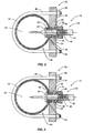
- Figures 1-3 illustrate a first embodiment of the connector assembly 10.
- the connector assembly 10 comprises an insert 40 adapted to pass through an opening 24 into the fluid chamber 20, a support assembly 30 to support the insert 40, a seal 50 disposed around an outer surface 45 of the insert 40 to seal the opening 24 into the fluid chamber 20, and a compression mechanism to compress the seal 50.
- the seal 50 When the seal 50 is compressed, the seal 50 radially expands and contacts the wall 26 of the opening 24 into the fluid chamber 20 to form a fluid tight seal.
- the connector assembly 10 is designed so that positive pressure inside the fluid chamber 20 enhances the seal that is formed. Additional, the connector assembly 10 is designed to minimize biological contamination risks and the transfer of thermal or electrical energy from the wall 22 to the insert 40.
- the support assembly 30 comprises a support member 31 , one or more U-bolts 36, and mounting nuts 38.
- Support member 31 has an opening 32 through which the insert 40 can be assembled via the proximal end of the insert.
- Mounting holes to accept the ends of U-bolts 36 are disposed on opposite sides of the opening 32.
- Support member 31 is positioned adjacent to fluid chamber 20 such that throughway opening 32 aligns with opening 24 in the chamber.
- the surface of the support member 31 facing the fluid chamber 20 may be contoured or machined so that it conforms to the shape of the fluid chamber 20 and provides a surface-to-surface contact.
- the support member 31 is affixed and anchored to the fluid chamber 20 with the U-bolt 36 and pair of mounting nuts 38. If desired, more than one U-bolt 36 or other form of clamping device can be used.
- the insert 40 may comprise a measurement probe, thermowell, or sleeve, or similar structure that extends into the fluid chamber 20.
- Insert 40 has a generally cylindrical body 42 with a flange 44 at the distal end. A portion of the outer surface 45 includes threads 46. Wrench flats 47 on the body 42 facilitate gripping the insert and preventing it from turning during installation or removal as hereinafter described.
- the proximal end of the insert 40 may have external threads 49 to provide a means of connecting an electrical housing or other conduit (not shown)
- Seal 50 has a generally annular shape with a central opening sized such that the seal 50 fits snugly around the insert 40.
- the insert 40 is positioned such that the seal 50 is disposed within the opening 24 in the fluid chamber 20 and such that a portion of the seal 50 extends into the interior 23 of the fluid chamber 20.
- the seal 50 radially expands when compressed to form a fluid-tight seal with the wall 26 of the opening 24.
- a portion of the seal 50 contacts the wall 26 of the opening.
- the portion of the seal 50 extending into the fluid chamber 20 expands beyond the wall 26.
- the diameter of the portion of the compressed seal 50 extending into the fluid chamber 20 is greater than the diameter of the opening 24.
- the profile of the opening 24 and seal 50 are shown as circular in shape, although other geometries are possible.
- the compression mechanism for compressing the seal 50 comprises first and second compression members disposed on opposite sides of seal 50 and an actuator 80 to squeeze the seal 50 between the compression members. At least one of these compression members is movable with respect to the insert 40 for engaging and compressing the seal 50.
- the flange 44 on the insert 40 functions as the first compression member.
- a shoulder 34 within the opening 32 of the support member 31 functions as the second compression member.
- the actuator 80 comprises a threaded nut 80 that engages with the external threaded portion 46 of the insert 40.
- a bushing 70 may be inserted between the actuator 80 and the support member 31 to provide electrical and/or thermal isolation for the insert 40 when made from non-conductive material.
- the actuator 80 is rotated in a direction such that the bushing 70 is driven into contact with the support member 31. Further rotation of actuator 80 retracts insert 40 and compresses seal 50 between the flange 44 and the shoulder 34 in the support member 31. Threaded portion 46 ends at a point along insert 40 such that it is not possible to over-compress the seal 50.
- Figures 4 - 5 illustrate a second embodiment that is similar in most respects to the first embodiment.
- the reference numbers used to denote components of the second embodiment are the same as the first embodiment where the components are similar. Detailed description of components previously described are omitted.
- the second embodiment is described below by highlighting the differences from the first embodiment.
- An object of the second embodiment is to allow the insert 40 to be installed and removed without dismantling the support member 31 from the chamber.
- the insert 40 in this embodiment comprises a sleeve with an axial opening 43 providing access to the interior of the fluid chamber 20.
- the throughway opening 32 in the support member 31 is enlarged enough to allow passage of the insert 40.
- the support member 31 in this embodiment comprises a mounting block that is integrally formed with the fluid chamber 20, or is permanently affixed to the fluid chamber 20, such as by welding.
- a removable support member 31, as shown in Figures 2 and 3 could also be used.
- the bushing 70 is designed to engage the seal 50, and function as the second compression member.
- Bushing 70 includes threads which engage mating threads in the support member 31.
- the bushing 70 is tightened to prevent the bushing 70 from moving axially relative to the support member 31.
- Seal 50 is thus positioned directly between flange 44 and bushing 70.
- the bushing 70 can also provide electrical and/or thermal isolation for the insert 40 when made from a non-conductive material.
- the second embodiment functions in substantially the same manner as the first embodiment.
- the actuator 80 comprises a nut that is tightened to compress the seal 50 as shown in Figure 5 . When the seal 50 is compressed, it expands radially into contact with the wall 26 of the opening 24 into the fluid chamber 20.
- actuator 80 is rotated to release the pressure on the seal 50. Due to the natural resiliency of the material, the seal 50 will contract so that the insert 40 and seal 50 can be withdrawn from the fluid chamber 20.
- seal 50 may include material having a low thermal conductivity to minimize the thermal energy transmitted through the seal.
- selecting a material for seal 50 having high electrical resistance will inhibit the transmission of electrical energy.
- insert 40, bushing 70, actuator 80 and/or support member 31 may be formed from thermal or electrical isolating material to prevent transfer of thermal or electrical energy from the wall 22 through the support member 31 to the insert 40.
- the connector assembly 10 is inserted into the opening 24 in the fluid chamber 20 and the actuator 80 is tightened by rotating the actuator 80.
- Rotation of the actuator 80 causes the insert 40 to move axially such that the seal 50 is compressed between the first and second compression members.
- the seal 50 radially expands when it is compressed. This radial expansion of the seal 50 creates a generally fluid-tight seal between the wall 26 of opening 24 and outer surface 45 of the insert 40.
- the fluid-tight seal provided effectively isolates fluid contained in the fluid chamber 20 from contact with exterior surfaces of the chamber. Moreover, no voids or crevices are created within the chamber which would give rise to stagnant areas. The absence of voids and crevices makes it possible to undertake clean-in-place (CIP) practices to ensure hygienic operating conditions. In addition, if the pressure within the chamber increases, the increased pressure will further compress the seal 50, which enhances the fluid-tight seal.
- CIP clean-in-place
- the connector assembly 10 of the present invention provides a device that permits access to the interior of a fluid chamber 20.
- the fluid chamber 20 may assume various forms, such as a pipe or vessel, and typically contains fluid being transported and/or undergoing some type of process.
- the fluid chamber 20 may be a closed system which totally isolates the fluid from the external environment, or the fluid chamber 20 could be an open vat or channel for directing the flow of a fluid.
- the connector assembly 10 permits access through the wall of a fluid chamber 20.
- the insert 40 may comprise a measurement probe for monitoring conditions inside the fluid chamber, or a thermowell.
- control and assessment of processes being carried out within the fluid chamber 20 may require bleeding or siphoning material from the fluid chamber 20 or injecting material into the fluid chamber 20.
- the insert 40 may comprise a sleeve with a fluid passage, therein allowing material to be introduced into or removed from the fluid chamber.
- the present invention can also be used to make a fluid connection between the fluid chamber 20 and a fluid conduit.
Landscapes
- Engineering & Computer Science (AREA)
- General Engineering & Computer Science (AREA)
- Mechanical Engineering (AREA)
- Infusion, Injection, And Reservoir Apparatuses (AREA)
- Pressure Vessels And Lids Thereof (AREA)
- Connector Housings Or Holding Contact Members (AREA)
- Measuring And Recording Apparatus For Diagnosis (AREA)
- External Artificial Organs (AREA)
Claims (15)
- Hygienische Einführungsanschlussanordnung (10), umfassend eine Einführung (40), welche eingerichtet ist, um durch eine Öffnung (24) in einer Kammer (20) derartig vorzustehen, dass ein erster Abschnitt der Einführung innerhalb der Kammer liegt; eine Dichtung (50) mit einem ersten und einem zweiten Ende und einer axialen Öffnung für die Einführung, wobei die Dichtung um die Einführung herum angeordnet ist, um einen Raum zwischen der Einführung und der Wand der Öffnung in der Kammer abzudichten, wobei sich das erste Ende der Dichtung über die Öffnung hinaus in die Flüssigkeitskammer erstreckt; ein erstes und ein zweites kooperatives Kompressionsbauteil (34, 44), welche auf entgegengesetzten Enden der Dichtung angeordnet sind, um die Dichtung derartig axial zu komprimieren und radial auszudehnen, dass eine im Allgemeinen für Flüssigkeiten dichte Dichtung zwischen der Wand der Öffnung und der Einführung ausgebildet wird; und wobei das erste Kompressionsbauteil (44) entlang einer Bewegungsachse hinsichtlich des zweiten Kompressionsbauteils (34) beweglich ist, um die Dichtung zu komprimieren, wobei die Einführungsanschlussanordnung durch Folgendes gekennzeichnet ist:eine erste Dichtungsfläche auf dem ersten Ende der Dichtung, wobei die Dichtungsfläche senkrecht zu der Bewegungsachse angeordnet ist; undKompressionskräfte, welche durch eine axiale Kompression der Dichtung erzeugt werden und welche senkrecht zu der ersten Dichtungsfläche sind.
- Hygienische Einführungsanschlussanordnung nach Anspruch 1, ein Steuerelement (80) aufweisend, um das erste Kompressionsbauteil hinsichtlich des zweiten Kompressionsbauteils zu bewegen, um die Dichtung zu komprimieren und radial ausdehnen.
- Hygienische Einführungsanschlussanordnung nach Anspruch 2, wobei das zweite Kompressionsbauteil stationär ist.
- Hygienische Einführungsanschlussanordnung nach Anspruch 3, wobei das erste Kompressionsbauteil einen Kragen (44) umfasst, welcher integral auf der Einführung ausgebildet ist.
- Hygienische Einführungsanschlussanordnung nach Anspruch 4, wobei das Steuerelement die Einführung axial hinsichtlich des zweiten Kompressionsbauteils bewegt.
- Hygienische Einführungsanschlussanordnung nach Anspruch 5, ein Stützbauteil (31) aufweisend, welches eingerichtet ist, um fest an der Kammer befestigt zu werden.
- Hygienische Einführungsanschlussanordnung nach Anspruch 6, wobei das zweite Kompressionsbauteil integral mit dem Stützbauteil ausgebildet ist.
- Hygienische Einführungsanschlussanordnung nach Anspruch 6, wobei das Stützbauteil integral mit der Flüssigkeitskammer ausgebildet ist.
- Hygienische Einführungsanschlussanordnung nach Anspruch 6, wobei das Kompressionsbauteil eine Hülse (70) umfasst, welche zwischen dem Steuerelement und dem Stützbauteil angeordnet ist, wobei die Hülse vorzugsweise verschraubbar in das Stützbauteil eingreift.
- Hygienische Einführungsanschlussanordnung nach Anspruch 4, wobei das Steuerelement ein Schraubbauteil (80) umfasst, welches auf die Einführung geschraubt ist.
- Hygienische Einführungsanschlussanordnung nach Anspruch 10, wobei die Anschlussanordnung konfiguriert ist, um die axiale Bewegung der Einführung zu begrenzen.
- Hygienische Einführungsanschlussanordnung nach Anspruch 1, wobei die Anschlussanordnung eingerichtet ist, um eine thermische und/oder elektrische Isolation der Einführung bereitzustellen.
- Hygienische Einführungsanschlussanordnung nach Anspruch 6, wobei Druck innerhalb der Kammer auf das erste Kompressionsbauteil einwirkt, um die Dichtung weiter gegen das zweite Kompressionsbauteil zu komprimieren, um die Dichtungsstärke zu verbessern.
- Hygienische Einführungsanschlussanordnung nach Anspruch 1, wobei die Einführung entweder einen Sensor, einen Temperaturmessstutzen oder ein Flüssigkeitsrohr umfasst.
- Hygienische Einführungsanschlussanordnung nach Anspruch 6, wobei beim Komprimieren der Dichtung das erste Kompressionsbauteil, die periphere Oberfläche der Dichtung innerhalb der Kammer und die Innenwand der Kammer benachbart zu der Öffnung zusammen eine kontinuierliche hygienische Oberfläche ohne Hohlräume oder Spalten ausbilden.
Applications Claiming Priority (2)
| Application Number | Priority Date | Filing Date | Title |
|---|---|---|---|
| US11/538,117 US7607364B2 (en) | 2006-10-03 | 2006-10-03 | Method and apparatus for simplified and hygienic access to a fluid chamber |
| PCT/GB2007/002711 WO2008040928A1 (en) | 2006-10-03 | 2007-07-18 | Method and apparatus for simplified an hygienic access to a fluid chamber |
Publications (2)
| Publication Number | Publication Date |
|---|---|
| EP2069678A1 EP2069678A1 (de) | 2009-06-17 |
| EP2069678B1 true EP2069678B1 (de) | 2012-01-25 |
Family
ID=38561732
Family Applications (1)
| Application Number | Title | Priority Date | Filing Date |
|---|---|---|---|
| EP07766279A Not-in-force EP2069678B1 (de) | 2006-10-03 | 2007-07-18 | Verfahren und vorrichtung für einen vereinfachten und hygienischen zugang zu einer fluidkammer |
Country Status (5)
| Country | Link |
|---|---|
| US (1) | US7607364B2 (de) |
| EP (1) | EP2069678B1 (de) |
| AT (1) | ATE543041T1 (de) |
| CA (1) | CA2664822C (de) |
| WO (1) | WO2008040928A1 (de) |
Families Citing this family (15)
| Publication number | Priority date | Publication date | Assignee | Title |
|---|---|---|---|---|
| US7387040B2 (en) * | 2005-08-19 | 2008-06-17 | Honeywell International Inc. | Methods and systems for mounting sensors for use in a harsh vibration environment |
| DE102006023464B4 (de) * | 2006-05-18 | 2010-04-15 | Continental Automotive Gmbh | Sensorbaugruppe mit einem an einer Wand montierbaren Gehäuse |
| US8235592B2 (en) * | 2009-10-07 | 2012-08-07 | Wika Alexander Wiegand Se & Co. Kg | Gauge on a pipe section |
| CN114099875B (zh) | 2011-06-03 | 2025-02-25 | 费雪派克医疗保健有限公司 | 医用管和制造方法 |
| GB2581265B (en) | 2012-11-14 | 2021-01-20 | Fisher & Paykel Healthcare Ltd | Zone heating for respiratory circuits |
| CN105339032B (zh) | 2012-12-04 | 2018-10-19 | 费雪派克医疗保健有限公司 | 医用管以及其制造方法 |
| US10814091B2 (en) | 2013-10-24 | 2020-10-27 | Fisher & Paykel Healthcare Limited | System for delivery of respiratory gases |
| HUE062413T2 (hu) | 2013-12-20 | 2023-10-28 | Fisher & Paykel Healthcare Ltd | Párásító rendszer csatlakozásai |
| AU2015232050B2 (en) | 2014-03-17 | 2020-01-23 | Fisher & Paykel Healthcare Limited | Medical tubes for respiratory systems |
| DE102014111985A1 (de) * | 2014-08-21 | 2016-02-25 | Endress + Hauser Wetzer Gmbh + Co. Kg | Verfahren zur Herstellung eines Messrohrs |
| US10960167B2 (en) | 2015-09-09 | 2021-03-30 | Fisher & Paykel Healthcare Limited | Zone heating for respiratory circuits |
| EP4523724A1 (de) | 2016-12-22 | 2025-03-19 | Fisher & Paykel Healthcare Limited | Medizinische schläuche und verfahren zur herstellung |
| DE102017115139A1 (de) * | 2017-07-06 | 2019-01-10 | Endress+Hauser SE+Co. KG | Messrohr und Messrohr zur Bestimmung und/oder Überwachung zumindest einer Prozessgröße eines Mediums |
| CN113324602B (zh) * | 2020-02-28 | 2026-01-13 | 斯伦贝谢技术有限公司 | 两件式微波同轴传感器和在垂直文丘里管的安置 |
| US11788625B2 (en) | 2020-05-27 | 2023-10-17 | Hoffman Enclosures, Inc. | Hygienic hole seal |
Family Cites Families (24)
| Publication number | Priority date | Publication date | Assignee | Title |
|---|---|---|---|---|
| US2515948A (en) * | 1946-04-27 | 1950-07-18 | Honeywell Regulator Co | Throttle device |
| US2966133A (en) * | 1958-12-31 | 1960-12-27 | American District Telegraph Co | Water flow detector |
| US3361944A (en) * | 1964-04-24 | 1968-01-02 | Shell Oil Co | Probe assembly for capacitance type monitoring device |
| US3863937A (en) * | 1973-11-02 | 1975-02-04 | Electro Protective Corp | Adapter gasket |
| US4267401A (en) * | 1978-07-03 | 1981-05-12 | Wilkinson William L | Seal plug |
| US4411458A (en) * | 1981-04-28 | 1983-10-25 | Strunk Norman E | Stem securing means for conduits |
| ATE38721T1 (de) * | 1982-08-24 | 1988-12-15 | Scottish & Newcastle Breweries | Verfahren zum ueberwachen einer gaskonzentration in einer fluessigkeit. |
| US4645242A (en) * | 1985-08-26 | 1987-02-24 | Dieterich Standard Corp. | High pressure mounting with positive lock |
| US4717159A (en) * | 1986-06-06 | 1988-01-05 | Dieterich Standard Corp. | Method and apparatus for seating and sealing a pitot tube type flow meter in a pipe |
| US4746127A (en) * | 1987-06-30 | 1988-05-24 | A-Lok Products, Inc. | Adjustable clamping band for gaskets and method for using same |
| US4836558A (en) * | 1987-10-20 | 1989-06-06 | Raychem Corporation | Bulkhead seal |
| RU2081708C1 (ru) * | 1991-05-04 | 1997-06-20 | Хейнкель Индустрицентрифуген ГмбХ унд Ко | Центрифуга с выворачиваемым фильтром |
| US5299594A (en) * | 1992-08-27 | 1994-04-05 | C.A.P., Inc. | Liquid flow rate detector |
| US5737822A (en) * | 1995-06-12 | 1998-04-14 | Insituform (Netherlands) B.V. | Corporation stop assembly |
| AU697697B2 (en) * | 1995-07-27 | 1998-10-15 | Georg Fischer Rohrleitungssysteme Ag | Device for measuring the quantity of flow and the rate of flow of a fluid inside a pipeline |
| US6193409B1 (en) * | 1999-06-10 | 2001-02-27 | Paul Mueller Company | Tank agitator having a clean-in-place shaft and seal assembly |
| DE10047758A1 (de) | 1999-10-21 | 2001-05-17 | Hewing Gmbh | Einsatz für eine Öffnung in einem insbesondere rohrförmigen Hohlkörper |
| US6773678B2 (en) * | 2000-03-20 | 2004-08-10 | Endress + Hauser Conducta Gesellschaft Fur Mess Und Regeltechnik Mbh + Co. | Mounting system and retractable sensor holder for analytical sensors |
| WO2001090607A2 (en) * | 2000-05-23 | 2001-11-29 | Tdm Industries, Inc. | Flexible seal forming member |
| US6467815B1 (en) * | 2000-11-17 | 2002-10-22 | Fab-Tech Incorporated | Fitting for installation of a nipple from the exterior of a duct and method of installation |
| US7135870B2 (en) * | 2004-05-04 | 2006-11-14 | Kam Controls Incorporated | Device for determining the composition of a fluid mixture |
| JP2008502868A (ja) | 2004-06-10 | 2008-01-31 | ファーメンタ、インコーポレイテッド | プロセス・ロックアウト・フィードバック手段を有するカップリング状態の監視システム |
| US7517566B2 (en) * | 2005-06-06 | 2009-04-14 | Konica Minolta Holdings, Inc. | Liquid crystal composition containing at least two kinds of gelling agents and liquid crystal display device using the same |
| DE202005013904U1 (de) | 2005-09-02 | 2006-02-09 | Elb-Form Ges.m.b.H. | Rohr mit Sensoradapter |
-
2006
- 2006-10-03 US US11/538,117 patent/US7607364B2/en active Active
-
2007
- 2007-07-18 EP EP07766279A patent/EP2069678B1/de not_active Not-in-force
- 2007-07-18 WO PCT/GB2007/002711 patent/WO2008040928A1/en not_active Ceased
- 2007-07-18 CA CA2664822A patent/CA2664822C/en active Active
- 2007-07-18 AT AT07766279T patent/ATE543041T1/de active
Also Published As
| Publication number | Publication date |
|---|---|
| CA2664822C (en) | 2015-01-06 |
| US7607364B2 (en) | 2009-10-27 |
| CA2664822A1 (en) | 2008-04-10 |
| US20080078259A1 (en) | 2008-04-03 |
| EP2069678A1 (de) | 2009-06-17 |
| ATE543041T1 (de) | 2012-02-15 |
| WO2008040928A8 (en) | 2012-03-01 |
| WO2008040928A1 (en) | 2008-04-10 |
Similar Documents
| Publication | Publication Date | Title |
|---|---|---|
| EP2069678B1 (de) | Verfahren und vorrichtung für einen vereinfachten und hygienischen zugang zu einer fluidkammer | |
| US8250937B2 (en) | Aseptic manifold and probe assembly | |
| US4580788A (en) | Split ring sealing device for high pressure service | |
| US8215193B2 (en) | Method and apparatus for simplified and hygienic access to a fluid chamber | |
| US20110163540A1 (en) | O-ringless seal couplings | |
| DK2644960T3 (en) | Combination of two tubes and a pipeline connector with compensator | |
| EP2459920B1 (de) | Vorrichtung zur reparatur und aufbereitung von rohrleitungen | |
| US20020066479A1 (en) | Dip tube valve assembly | |
| EP0897499B1 (de) | Rohrverbindung und dichtung dafür | |
| JP6349566B2 (ja) | 一軸偏心ネジポンプ | |
| US20020041099A1 (en) | Releasable pipe-connecting arrangement | |
| US4268070A (en) | Orifice flange clamp | |
| US20040160055A1 (en) | Pipe seal | |
| US10352454B2 (en) | Mechanical seal device | |
| US20020003348A1 (en) | Pipe joint and a gasket therefor | |
| RU2352849C1 (ru) | Устройство для монтажа труб | |
| WO2005059421A1 (en) | Pipe seal | |
| EP3252363B1 (de) | Kupplungsanordnung zum verbinden zweier rohrabschnitte | |
| US4795134A (en) | Valve with improved sealing properties | |
| US7884290B2 (en) | Sanitary, live loaded, pass through fitting apparatus | |
| US20250183631A1 (en) | Method and a tight connector, for fixing a cable especially an electrical one | |
| CN118375799A (zh) | 管道连接系统 | |
| KR20170124174A (ko) | 배관 마감하는 장치 | |
| CN117949026A (zh) | 过程连接件、传感器组件以及过程设备 | |
| Clem | 12 Cleanable In-Line Components |
Legal Events
| Date | Code | Title | Description |
|---|---|---|---|
| PUAI | Public reference made under article 153(3) epc to a published international application that has entered the european phase |
Free format text: ORIGINAL CODE: 0009012 |
|
| 17P | Request for examination filed |
Effective date: 20090327 |
|
| AK | Designated contracting states |
Kind code of ref document: A1 Designated state(s): AT BE BG CH CY CZ DE DK EE ES FI FR GB GR HU IE IS IT LI LT LU LV MC MT NL PL PT RO SE SI SK TR |
|
| AX | Request for extension of the european patent |
Extension state: AL BA HR MK RS |
|
| 17Q | First examination report despatched |
Effective date: 20100729 |
|
| GRAP | Despatch of communication of intention to grant a patent |
Free format text: ORIGINAL CODE: EPIDOSNIGR1 |
|
| DAX | Request for extension of the european patent (deleted) | ||
| GRAS | Grant fee paid |
Free format text: ORIGINAL CODE: EPIDOSNIGR3 |
|
| GRAA | (expected) grant |
Free format text: ORIGINAL CODE: 0009210 |
|
| AK | Designated contracting states |
Kind code of ref document: B1 Designated state(s): AT BE BG CH CY CZ DE DK EE ES FI FR GB GR HU IE IS IT LI LT LU LV MC MT NL PL PT RO SE SI SK TR |
|
| REG | Reference to a national code |
Ref country code: GB Ref legal event code: FG4D |
|
| REG | Reference to a national code |
Ref country code: CH Ref legal event code: EP |
|
| REG | Reference to a national code |
Ref country code: AT Ref legal event code: REF Ref document number: 543041 Country of ref document: AT Kind code of ref document: T Effective date: 20120215 |
|
| REG | Reference to a national code |
Ref country code: IE Ref legal event code: FG4D |
|
| RTI2 | Title (correction) |
Free format text: METHOD AND APPARATUS FOR SIMPLIFIED AND HYGIENIC ACCESS TO A FLUID CHAMBER |
|
| REG | Reference to a national code |
Ref country code: DE Ref legal event code: R096 Ref document number: 602007020278 Country of ref document: DE Effective date: 20120322 |
|
| REG | Reference to a national code |
Ref country code: NL Ref legal event code: T3 |
|
| LTIE | Lt: invalidation of european patent or patent extension |
Effective date: 20120125 |
|
| PG25 | Lapsed in a contracting state [announced via postgrant information from national office to epo] |
Ref country code: BE Free format text: LAPSE BECAUSE OF FAILURE TO SUBMIT A TRANSLATION OF THE DESCRIPTION OR TO PAY THE FEE WITHIN THE PRESCRIBED TIME-LIMIT Effective date: 20120125 Ref country code: LT Free format text: LAPSE BECAUSE OF FAILURE TO SUBMIT A TRANSLATION OF THE DESCRIPTION OR TO PAY THE FEE WITHIN THE PRESCRIBED TIME-LIMIT Effective date: 20120125 Ref country code: IS Free format text: LAPSE BECAUSE OF FAILURE TO SUBMIT A TRANSLATION OF THE DESCRIPTION OR TO PAY THE FEE WITHIN THE PRESCRIBED TIME-LIMIT Effective date: 20120525 Ref country code: BG Free format text: LAPSE BECAUSE OF FAILURE TO SUBMIT A TRANSLATION OF THE DESCRIPTION OR TO PAY THE FEE WITHIN THE PRESCRIBED TIME-LIMIT Effective date: 20120425 |
|
| PG25 | Lapsed in a contracting state [announced via postgrant information from national office to epo] |
Ref country code: FI Free format text: LAPSE BECAUSE OF FAILURE TO SUBMIT A TRANSLATION OF THE DESCRIPTION OR TO PAY THE FEE WITHIN THE PRESCRIBED TIME-LIMIT Effective date: 20120125 Ref country code: LV Free format text: LAPSE BECAUSE OF FAILURE TO SUBMIT A TRANSLATION OF THE DESCRIPTION OR TO PAY THE FEE WITHIN THE PRESCRIBED TIME-LIMIT Effective date: 20120125 Ref country code: PT Free format text: LAPSE BECAUSE OF FAILURE TO SUBMIT A TRANSLATION OF THE DESCRIPTION OR TO PAY THE FEE WITHIN THE PRESCRIBED TIME-LIMIT Effective date: 20120525 Ref country code: GR Free format text: LAPSE BECAUSE OF FAILURE TO SUBMIT A TRANSLATION OF THE DESCRIPTION OR TO PAY THE FEE WITHIN THE PRESCRIBED TIME-LIMIT Effective date: 20120426 Ref country code: PL Free format text: LAPSE BECAUSE OF FAILURE TO SUBMIT A TRANSLATION OF THE DESCRIPTION OR TO PAY THE FEE WITHIN THE PRESCRIBED TIME-LIMIT Effective date: 20120125 |
|
| REG | Reference to a national code |
Ref country code: AT Ref legal event code: MK05 Ref document number: 543041 Country of ref document: AT Kind code of ref document: T Effective date: 20120125 |
|
| PG25 | Lapsed in a contracting state [announced via postgrant information from national office to epo] |
Ref country code: CY Free format text: LAPSE BECAUSE OF FAILURE TO SUBMIT A TRANSLATION OF THE DESCRIPTION OR TO PAY THE FEE WITHIN THE PRESCRIBED TIME-LIMIT Effective date: 20120125 |
|
| REG | Reference to a national code |
Ref country code: GB Ref legal event code: S117 Free format text: REQUEST FILED; REQUEST FOR CORRECTION UNDER SECTION 117 FILED ON 22 AUGUST 2012 |
|
| PG25 | Lapsed in a contracting state [announced via postgrant information from national office to epo] |
Ref country code: CZ Free format text: LAPSE BECAUSE OF FAILURE TO SUBMIT A TRANSLATION OF THE DESCRIPTION OR TO PAY THE FEE WITHIN THE PRESCRIBED TIME-LIMIT Effective date: 20120125 Ref country code: RO Free format text: LAPSE BECAUSE OF FAILURE TO SUBMIT A TRANSLATION OF THE DESCRIPTION OR TO PAY THE FEE WITHIN THE PRESCRIBED TIME-LIMIT Effective date: 20120125 Ref country code: DK Free format text: LAPSE BECAUSE OF FAILURE TO SUBMIT A TRANSLATION OF THE DESCRIPTION OR TO PAY THE FEE WITHIN THE PRESCRIBED TIME-LIMIT Effective date: 20120125 Ref country code: EE Free format text: LAPSE BECAUSE OF FAILURE TO SUBMIT A TRANSLATION OF THE DESCRIPTION OR TO PAY THE FEE WITHIN THE PRESCRIBED TIME-LIMIT Effective date: 20120125 Ref country code: SI Free format text: LAPSE BECAUSE OF FAILURE TO SUBMIT A TRANSLATION OF THE DESCRIPTION OR TO PAY THE FEE WITHIN THE PRESCRIBED TIME-LIMIT Effective date: 20120125 Ref country code: SE Free format text: LAPSE BECAUSE OF FAILURE TO SUBMIT A TRANSLATION OF THE DESCRIPTION OR TO PAY THE FEE WITHIN THE PRESCRIBED TIME-LIMIT Effective date: 20120125 |
|
| REG | Reference to a national code |
Ref country code: GB Ref legal event code: S117 Free format text: CORRECTIONS ALLOWED; REQUEST FOR CORRECTION UNDER SECTION 117 FILED ON 22 AUGUST 2012 ALLOWED ON 15 OCTOBER 2012 |
|
| PG25 | Lapsed in a contracting state [announced via postgrant information from national office to epo] |
Ref country code: IT Free format text: LAPSE BECAUSE OF FAILURE TO SUBMIT A TRANSLATION OF THE DESCRIPTION OR TO PAY THE FEE WITHIN THE PRESCRIBED TIME-LIMIT Effective date: 20120125 Ref country code: SK Free format text: LAPSE BECAUSE OF FAILURE TO SUBMIT A TRANSLATION OF THE DESCRIPTION OR TO PAY THE FEE WITHIN THE PRESCRIBED TIME-LIMIT Effective date: 20120125 |
|
| PLBE | No opposition filed within time limit |
Free format text: ORIGINAL CODE: 0009261 |
|
| STAA | Information on the status of an ep patent application or granted ep patent |
Free format text: STATUS: NO OPPOSITION FILED WITHIN TIME LIMIT |
|
| 26N | No opposition filed |
Effective date: 20121026 |
|
| PG25 | Lapsed in a contracting state [announced via postgrant information from national office to epo] |
Ref country code: AT Free format text: LAPSE BECAUSE OF FAILURE TO SUBMIT A TRANSLATION OF THE DESCRIPTION OR TO PAY THE FEE WITHIN THE PRESCRIBED TIME-LIMIT Effective date: 20120125 |
|
| REG | Reference to a national code |
Ref country code: DE Ref legal event code: R097 Ref document number: 602007020278 Country of ref document: DE Effective date: 20121026 |
|
| PG25 | Lapsed in a contracting state [announced via postgrant information from national office to epo] |
Ref country code: MC Free format text: LAPSE BECAUSE OF NON-PAYMENT OF DUE FEES Effective date: 20120731 |
|
| REG | Reference to a national code |
Ref country code: CH Ref legal event code: PL |
|
| PG25 | Lapsed in a contracting state [announced via postgrant information from national office to epo] |
Ref country code: LI Free format text: LAPSE BECAUSE OF NON-PAYMENT OF DUE FEES Effective date: 20120731 Ref country code: ES Free format text: LAPSE BECAUSE OF FAILURE TO SUBMIT A TRANSLATION OF THE DESCRIPTION OR TO PAY THE FEE WITHIN THE PRESCRIBED TIME-LIMIT Effective date: 20120506 Ref country code: CH Free format text: LAPSE BECAUSE OF NON-PAYMENT OF DUE FEES Effective date: 20120731 |
|
| REG | Reference to a national code |
Ref country code: IE Ref legal event code: MM4A |
|
| PG25 | Lapsed in a contracting state [announced via postgrant information from national office to epo] |
Ref country code: IE Free format text: LAPSE BECAUSE OF NON-PAYMENT OF DUE FEES Effective date: 20120718 Ref country code: MT Free format text: LAPSE BECAUSE OF FAILURE TO SUBMIT A TRANSLATION OF THE DESCRIPTION OR TO PAY THE FEE WITHIN THE PRESCRIBED TIME-LIMIT Effective date: 20120125 |
|
| PG25 | Lapsed in a contracting state [announced via postgrant information from national office to epo] |
Ref country code: TR Free format text: LAPSE BECAUSE OF FAILURE TO SUBMIT A TRANSLATION OF THE DESCRIPTION OR TO PAY THE FEE WITHIN THE PRESCRIBED TIME-LIMIT Effective date: 20120125 |
|
| PG25 | Lapsed in a contracting state [announced via postgrant information from national office to epo] |
Ref country code: LU Free format text: LAPSE BECAUSE OF NON-PAYMENT OF DUE FEES Effective date: 20120718 |
|
| PG25 | Lapsed in a contracting state [announced via postgrant information from national office to epo] |
Ref country code: HU Free format text: LAPSE BECAUSE OF FAILURE TO SUBMIT A TRANSLATION OF THE DESCRIPTION OR TO PAY THE FEE WITHIN THE PRESCRIBED TIME-LIMIT Effective date: 20070718 |
|
| REG | Reference to a national code |
Ref country code: FR Ref legal event code: PLFP Year of fee payment: 10 |
|
| REG | Reference to a national code |
Ref country code: FR Ref legal event code: PLFP Year of fee payment: 11 |
|
| REG | Reference to a national code |
Ref country code: FR Ref legal event code: PLFP Year of fee payment: 12 |
|
| PGFP | Annual fee paid to national office [announced via postgrant information from national office to epo] |
Ref country code: NL Payment date: 20180719 Year of fee payment: 12 Ref country code: FR Payment date: 20180725 Year of fee payment: 12 Ref country code: DE Payment date: 20180723 Year of fee payment: 12 |
|
| REG | Reference to a national code |
Ref country code: DE Ref legal event code: R119 Ref document number: 602007020278 Country of ref document: DE |
|
| PG25 | Lapsed in a contracting state [announced via postgrant information from national office to epo] |
Ref country code: DE Free format text: LAPSE BECAUSE OF NON-PAYMENT OF DUE FEES Effective date: 20200201 Ref country code: NL Free format text: LAPSE BECAUSE OF NON-PAYMENT OF DUE FEES Effective date: 20190801 |
|
| REG | Reference to a national code |
Ref country code: NL Ref legal event code: MM Effective date: 20190801 |
|
| PG25 | Lapsed in a contracting state [announced via postgrant information from national office to epo] |
Ref country code: FR Free format text: LAPSE BECAUSE OF NON-PAYMENT OF DUE FEES Effective date: 20190731 |
|
| PGFP | Annual fee paid to national office [announced via postgrant information from national office to epo] |
Ref country code: GB Payment date: 20220714 Year of fee payment: 16 |
|
| GBPC | Gb: european patent ceased through non-payment of renewal fee |
Effective date: 20230718 |
|
| PG25 | Lapsed in a contracting state [announced via postgrant information from national office to epo] |
Ref country code: GB Free format text: LAPSE BECAUSE OF NON-PAYMENT OF DUE FEES Effective date: 20230718 |