EP2070071B1 - Système de rétroéclairage à diodes électroluminescentes pour caisson - Google Patents
Système de rétroéclairage à diodes électroluminescentes pour caisson Download PDFInfo
- Publication number
- EP2070071B1 EP2070071B1 EP07843847.0A EP07843847A EP2070071B1 EP 2070071 B1 EP2070071 B1 EP 2070071B1 EP 07843847 A EP07843847 A EP 07843847A EP 2070071 B1 EP2070071 B1 EP 2070071B1
- Authority
- EP
- European Patent Office
- Prior art keywords
- panels
- panel
- led
- leds
- sign
- Prior art date
- Legal status (The legal status is an assumption and is not a legal conclusion. Google has not performed a legal analysis and makes no representation as to the accuracy of the status listed.)
- Not-in-force
Links
Images










Classifications
-
- G—PHYSICS
- G09—EDUCATION; CRYPTOGRAPHY; DISPLAY; ADVERTISING; SEALS
- G09F—DISPLAYING; ADVERTISING; SIGNS; LABELS OR NAME-PLATES; SEALS
- G09F9/00—Indicating arrangements for variable information in which the information is built-up on a support by selection or combination of individual elements
- G09F9/30—Indicating arrangements for variable information in which the information is built-up on a support by selection or combination of individual elements in which the desired character or characters are formed by combining individual elements
- G09F9/33—Indicating arrangements for variable information in which the information is built-up on a support by selection or combination of individual elements in which the desired character or characters are formed by combining individual elements being semiconductor devices, e.g. diodes
-
- G—PHYSICS
- G09—EDUCATION; CRYPTOGRAPHY; DISPLAY; ADVERTISING; SEALS
- G09F—DISPLAYING; ADVERTISING; SIGNS; LABELS OR NAME-PLATES; SEALS
- G09F13/00—Illuminated signs; Luminous advertising
- G09F13/20—Illuminated signs; Luminous advertising with luminescent surfaces or parts
- G09F13/22—Illuminated signs; Luminous advertising with luminescent surfaces or parts electroluminescent
-
- G—PHYSICS
- G09—EDUCATION; CRYPTOGRAPHY; DISPLAY; ADVERTISING; SEALS
- G09F—DISPLAYING; ADVERTISING; SIGNS; LABELS OR NAME-PLATES; SEALS
- G09F7/00—Signs, name or number plates, letters, numerals, or symbols; Panels or boards
-
- G—PHYSICS
- G09—EDUCATION; CRYPTOGRAPHY; DISPLAY; ADVERTISING; SEALS
- G09F—DISPLAYING; ADVERTISING; SIGNS; LABELS OR NAME-PLATES; SEALS
- G09F13/00—Illuminated signs; Luminous advertising
- G09F13/20—Illuminated signs; Luminous advertising with luminescent surfaces or parts
- G09F13/22—Illuminated signs; Luminous advertising with luminescent surfaces or parts electroluminescent
- G09F2013/222—Illuminated signs; Luminous advertising with luminescent surfaces or parts electroluminescent with LEDs
Definitions
- the present exemplary embodiments relate to a Backlighting system. It finds particular application in conjunction with the signage industry.
- One particular application for such a backlighting system is a cabinet sign, and it will be described with particular reference thereto.
- the present exemplary embodiment is also amenable to other like applications.
- US 6,167,648 discloses an illuminatable sign includes a number of lighting modules arranged on an electrical circuit such that they are individually disconnectable, removable and adjustable in position between conductors. Preferably the lighting modules are slidable on the conductors while remaining in electrical contact to provide illumination where it is specifically required. Connections between the modules and the conductors may be such that the modules slide on the conductors. Such connectors may be snap on connectors or may be prongs insertable into helical springs about the conductors such that compression of the springs increases the diameter of the springs to allow them to slide on the conductors and lack of compression allows the springs to grip the prongs tightly.
- US 2003/0031032 discloses a light emitting diode module for attaching to a surface of a sign, which includes a mounting plate having top and bottom surfaces, a plurality of light emitting diodes mounted to the top surface of the mounting plate, a housing having top and bottom surfaces, a first electrical connector attached to the bottom surface of the mounting plate and electrically connected to the plurality of light emitting diodes, a second electrical connector attached to the top surface of the housing for engaging with the first electrical connector, a third electrical connector attached to the housing and electrically connected to the second electrical connector, and a power supply for providing a voltage to the third electrical connector.; As the bottom surface of the mounting plate is placed on the top surface of the housing, the first electrical connector engages with the second electrical connector for electrically connecting the plurality of light emitting diodes to the third electrical connector.
- the mounting plate could be integrally formed as part of the housing, and the first and second electrical connectors omitted.
- US 6,505,956 discloses a reeled L.E.D. lighting system has a plurality of rigid circuit boards, each circuit board having a plurality of light emitting diodes dispersed on one face thereof, the diodes being electrically connected between positive and negative terminals of their respective circuit board, the circuit boards being electrically connected in parallel with each other and structurally connected in series with each other by a plurality of pairs of flexible conductors connecting the positive and negative terminals of the circuit boards, the structural series connection providing a chain of the circuit boards and conductors, the chain being spirally wound about a spool of a reel for every dispersion into and attachment to a light housing.
- US 2005/0231943 disclose a channel letter lighting system according to the present invention comprising a channel letter housing with a translucent channel letter cover.
- a plurality of electrically connected lighting units are mounted to the channel letter housing and conductors provide an electrical signal to each of the units.
- Each of the units comprises a lighting unit housing and a printed circuit board (PCB) mounted within said housing.
- the PCB has a plurality of light emitting elements, such as light emitting diodes, with the electrical signal applied to the light emitting elements causing them to generate light substantially away from the housing.
- the PCB conducts and dissipates heat from the light emitting elements, the unit further comprises a space between most of the PCB and the lighting unit housing to allow heat from the PCB to dissipate into the surrounding ambient.
- a mounting mechanism is included for each unit to the channel letter housing.
- an LED light engine includes a flexible electrical cable and a plurality of LEDs.
- the flexible electrical cable includes first, second and third electrical conductors and an electrically insulating covering for the electrical conductors.
- the conductors are arranged substantially parallel with one another having an insulating material therebetween.
- a first LED including a first lead electrically connects to the first electrical conductor and a second lead of the first LED electrically connects to the second conductor.
- a second LED includes a first lead electrically connected to the second electrical conductor and a second lead electrically connected to the third electrical conductor.
- a third LED includes first and second leads electrically connected to the second conductor.
- the third LED is interposed between the first LED and the second LED US 2005/0122293 discloses a chain of LEDs is formed from link units connected by wire pairs in electrical circuit. At least one wire pair is connected to a link unit to form external power supply wires.
- Each link unit is made of a tray housing a PCB in the housing, and LEDs mounted on the PCB in electrical connection with the wire pairs. Cured waterproof resin inside the tray housing encases the printed circuit board, the wire pair connection point to the PCB and the lower half of the light emitting diode elements.
- the present invention discloses a backlighting system for a cabinet sign comprising: an enclosure including a front sign face and a back section; a plurality of panels each panel including: a plurality of light emitting diodes ("LEDs") attached to the panel, wherein the distance that each LED is from the sign face of the enclosure divided by the distance between the subject LED and the closest adjacent LED provides a ratio of less than 1.4, and an integrated circuit; and a wire wherein the wire physically connects adjacent panels and characterized in that the plurality of panels are attached to each of one or more rails.
- LEDs light emitting diodes
- An embodiment disclosed here includes a plurality of panels which comprise the backlighting system.
- Each panel includes a plurality of LEDs.
- the LEDs are spaced away from each other on the same panel and likewise relative to LEDs on adjacent panels such that the backlighting system will exhibit lighting qualities similar to those of a fluorescent backlit system.
- the LED backlit system will exhibit uniformity, brightness, and color rendering consistent with that of a fluorescent backlit system.
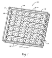
- FIG. 1 illustrated is a front view of a backlighting system, 100, for a cabinet sign.
- the depicted system 100 includes a frame 102 and a plurality of panels 104.
- Panels 104 are attached to frame 102 in a plurality of rows as shown.
- panels 104 may be attached to frame 102 in plurality of columns instead of rows.
- Individual panels 104 are not limited to any particular size. Given that typically a box sign is square or rectangular, a particular useful panel size is 1' x 1' [30.5cm x 30.5cm]. Manufacturers of cabinet signs may find this size panel desirable in that it may be used to make the lighting system for cabinet signs of various sizes.
- the cabinet sign has a sign surface having an area of the sign less than about 200 square feet (ft 2 ) [18.6m 2 ].
- the surface area of the sign may range from about 4 up to about 200 square feet (ft 2 ) [0.372 m 2 up to about 18.6m 2 ].
- a flexible material e.g., a vinyl based material, etc.
- the surface area of the sign can be much greater than 200 square feet [18.6m 2 ].
- panels 104 may be rectangular in shape. Panels 104 are not limited to any particular shape or size. Panels 104 are depicted in rectangular and square shapes due to the reason that these are believed to be desirable shapes for sign manufacturers. Panels having other shapes may be manufactured, if desired by an end user. Also, panels of different shapes and/or sizes may be used in the same cabinet sign.
- panel 104 may be a printed wiring board.
- the printed wiring board may be one selected from the group of a printed circuit board, a metal clad printed circuit board, and a flexible circuit.
- the flexible circuit may include a backing plate. Two examples of preferred materials for the backing plate include aluminum or plastic. Flex circuits are available at least from the following sources: Minco of Minneapolis, MN, Allflex Inc. of Northfield, MN, and Unifilex Circuits of San Jose, CA.
- the printed wiring board may include LEDs connected together with a wire in the form of a strip and then the strip is attached to a backing. Typically, the backing may be made of aluminum or plastic.
- each panel 104 includes a plurality of light emitting diodes ("LEDs") 106.
- LEDs 106 may be arranged in any particular pattern on panel 104. Also, the number of LEDs 106 on each panel may vary or may be uniform. In one particular embodiment, each LED 106 is no more than 4" [10.2cm] away from one or more adjacent LEDs. In another embodiment, LED spacing may be determined by the box sign depth factor. This is the ratio of the distance the LED is from the sign face of the cabinet sign ("depth") divided by the distance between the closest adjacent LED and the subject LED. For example, if the subject LED is 4" [10.2 cm] away from the closest adjacent LED and the depth of the LED below the sign is 4" [10.2cm], the factor is 1.
- the sign box depth factor is about 1.33.
- a preferred factor is less than about 1.4. in another particular embodiment, the factor may range from about 1.25 to about 0.5. In a further embodiment, the LEDs may be randomly or uniformly spaced apart from one another. in one certain embodiment, each LED is substantially equally spaced apart from its adjacent LEDs.
- any suitable type of LED may be used in conjunction with the panel 104.
- Examples of typical types of LEDs which may be used include surface mount LEDs and hole through LEDs.
- Panel 104 is not limited to a particular number of LEDs 106. Any desired number of LEDs may be used.
- a typical panel 104 may have anywhere from four (4) to twelve (12) LEDs associated with it.
- LEDs 106 do not have to have any specific wattage requirement. In one particular application LED 106 wattage may be 1W or 0.5 W. As for panel 104, in one particular embodiment it is preferred that the light emitted by LEDs 106 on panel 104 has a brightness of up to about 1500 nits candela per square metre, measured at the outside surface of the sign face of the sign.
- Panel 104 may also include one or more integrated circuits 108. Integrated circuits 108 may be used to drive LEDs 106 on panel 104.
- panel 104 may include one or more LED protective elements. This is an element which may protect the diode of the LED from coming in physical contact with another tangible item.
- the protective element may comprise a ring shaped cone on the surface of panel 104 in which LED 106 is in the center of the recessed portion of the cone.
- the protective element may be a clear plastic cap over the top of the diode of each LED.
- panels 104 may be attached to one or more rails 110.
- the rails may be constructed from any material which is known to be suitable for use as a heat sink; non-limiting examples include aluminum and natural graphite.
- Panels 104 may be attached by any know attachment technique. As illustrated panels 104 are attached by the use of screws 112.
- panels 104 may be fixed to rails 110 or adjustably attached to rails 110, as shown.
- Rails 110 may be attached to frame 102 by any known attachment technique.
- panels 104 may include one or more integral or attachable guides that mate with a portion of rails 110 and enable panels 104 to easily move along rails 110.
- rails 110 may be adjustably attached to frame 102 by the use of a clamping element, 114.
- other adjustable attachment elements may be used instead of clamping element 114 or fixed attachment elements may be used in place of clamping element 114.
- Panels 104 may be uniformly spaced apart or randomly spaced apart. In one particular embodiment, the spacing between any two adjustably attached adjacent panels 104 on the same rail 110 may be adjusted to a desired distance.
- Panel 104 may also include one or more terminals 116. The terminals may be used to connect two (2) adjacent panels 104 together.
- FIGURE 3 Depicted in FIGURE 3 is a front view of one embodiment of an optional component of panel 104.
- panel 104 may include a core plate 105.
- core plate 105 includes one or more openings 118.
- openings 118 are sized and spaced so not to detract from the structural integrity of panel 104 but to improve at least the ability of panel 104 to transfer heat away from the LEDs and optionally also the strength of core plate 105. Openings 118 may be uniformly or randomly oriented on panel 104.
- Examples of preferable materials of construction of core plate 105 include steel, steel alloys, aluminum, aluminum alloys, natural graphite, extruded plastic, any other material which may be used as a heat sink and have sufficient structural integrity, and combinations thereof.
- panel 104 may include a thin ceramic coat 120 encapsulating core plate 105.
- Panel 104 may also include an over mold 122.
- over mold 122 is made from weather resilient material and has a transparent top surface. Examples of materials which may be used to make over mold 122 include silicone, epoxy, or a plastic extrusion.
- the plastic extrusion may be formed from thermoplastic elastomers (thermo-conductive or non thermo-conductive), polyvinyl chloride, acrylic, polyethylene (high density or low density), polypropylene, polystryrene, and ABS.
- Over mold 122 may attach to a top surface of panel 104 or alternatively may attach to a side or bottom surface of panel 104, as shown in FIGURE 5 .
- panel 104 may include one or more optional feet 125. Preferably feet 125 extend away from panel 104 from an underside of panel 104. Preferably, over mold 122 does not cover a top surface of LEDs 106.
- panel 104 and over mold 122 include a printed circuit board panel and a plastic or silicone over mold, a metal clad circuit board and a plastic or silicone over mold, and a flex circuit on an aluminum or plastic backing and a plastic or silicone over mold.
- the plastic may be a thermoplastic elastomer or other type of suitable polymer which may be formed into plastic.
- panel 104 may include openings and pins may be used to maintain panel 104 in a fixed position during the over molding process. If desired in a second embodiment, the openings used may be filled in a separate over molding step or the holes may be filled with a filler.
- panels 104 may be encased in a snap together plastic housing.
- the housing may include connecting front and back sections which may be used as an enclosure to protect the board. It is preferred that the front section of housing includes openings aligned with LEDs 106 for the emission of the light generated by LEDs 106.
- Over mold 122 or the housing may be used to connect a plurality of panels 104 having a one-dimensional array to form a panel having a two-dimensional array.
- two or more panels, such as shown in Figure 10 , 104R may be over molded at the same time to form a composite panel having the LEDs arranged in two dimensions. The resulting panel would have an orientation similar to that of the panel 104L, shown in Figure 12 .
- a housing may be used to form a plurality of panels 104R having a one-dimensional array into a two-dimensional array. Such a housing would encase two or more panels to align LEDs 106 in the width and length direction of the housing.
- FIG. 6 to 9 An arrangement 130 of panels 104 not comprising part of the claimed invention is illustrated in Figures 6 to 9 .
- a plurality of panels 104 is arranged in columns. Adjacent panels 104 in each column are attached by one or more flexible strips 126.
- flexible strips 126 mechanically connect adjacent panels 104.
- flexible strips 126 may also electrically connect adjacent panels 104.
- Preferably flexible strips 126 have sufficient flexibility that strips 126 may be used to fold panels 104 of system 100 one on top of another, as illustrated in FIGURE 8 .
- panels 104 may be shipped in the folded orientation as shown in FIGURE 13A .
- one fold may occur between row 104A of panels 104 and row 104B of panels 104 and another fold may occur between row 104B of panels 104 and row 104C of panels 104.
- a connector 128 is used to attach the end panel 104 of each column to a support 124.
- suitable materials for flexible strip 126 are a ribbon cable and a Mylar flex connection. These exemplary materials may also be used to supply power between adjacent panels.
- strip 126 includes a wire
- the wire may optionally be either a two conductor wire or a three conductor wire.
- Supports 124 may be attached to frame 102 of a cabinet sign.
- One or more of the arrangements 130 may be used to form the system 100 for a cabinet sign.
- flexible strips 126 may be used to attach panels 104 to support 124.
- flexible strips 126 may be used to attach panels 104 to frame 102 instead of support 124.
- FIGURE 10 An alternate embodiment of panels 104R is depicted in FIGURE 10 .
- panel 104R has a rectangular shape and LEDs 106 are arranged in a single file line along the length of panel 104R. This may also be referred to as arranging LEDs 106 in a one dimensional pattern, whereas in FIGURE 2 , LEDs 106 are arranged in a 2-dimensional pattern.
- each rail 110 includes a recess to engage a locking element 129.
- locking element 129 includes a bolt sized to fit into recess 127.
- recess 127 may be sized to engage the feet of panel 104R similar, but not limited, to feet 125 depicted in FIGURE 5 .
- Each pair of panels 104R may include a bracket in between adjacent panels 104R.
- the bracket may be a unitary element which connects two adjacent panels 104R.
- Each panel 104R may include a receiving element for the bracket.
- the bracket may have a recess such that it will be able to receive another panel 104R to align a plurality of panels in a manner similar to as shown in Figure 14 .
- a portion of the bracket may be attached to each of the panels 104R and mate with a complimentary portion of the bracket on the adjacent panel 104R.
- the bracket may include a hinge such that a fold may be formed relative to the two adjacent panels.
- the brackets may be detachable; such that the bracket may be detached from a panel or that the bracket may be separated into two (2) sections.
- one end of panels 104R may include a port for connecting a power source to panel 104R.
- a second end of the panel 104R may include an electrical connector to adjoin adjacent panels 104R in the horizontal direction of the backlighting system.
- Panel 104L may be any desired dimension, such as but not limited to about twelve inches (12") [30.5cm] wide (depicted a "W") and a height of about four inches (4") [10.2cm] to about six inches (6") [15.2cm] (depicted as "H”).
- the LEDs 106 are spaced at least about two inches (2") [5.1 cm], but no more than six inches (6") [15.2cm], apart from an adjacent LED 106.
- adjacent panels 104L are connected by flexible strips 126.
- panels 104L may be connected to a bus, not shown.
- the plurality 134 of panels 104L may be folded one on top of the other as shown in FIGURE 13A , or rolled into a convenient shape of packaging and transporting to a desired location. As shown, one convenient shape is the substantially cylindrical type shaped roll of the plurality 134 illustrated in FIGURE 13 .
- each LED may be about four inches (4") [10.2cm] apart for an adjacent LED.
- the 4" [10.2cm] spacing may also apply to adjacent LEDs 106 on adjacent panels 104L.
- Adjacent panels 104L may be arranged either horizontally or vertically to one another. Dimensions of a panel, long on one side (e.g., nine inches [22.9cm]), short on the other (e.g., less than five inches [12.7cm]) can provide easier fit within rectangular cabinet sign and, by adjusting orientation of layout, may accommodate a greater number of box signs of varying heights and widths.
- panels 104L may be stacked one on top of another as shown In FIGURE 14 .
- the panels 104L are stacked in an offset relationship to one another such that the light emitting from those LEDs 106 on a lower panel 104L is not blocked by the upper panel 104L.
- This technique may be used to increase the density of the LEDs in a particular area of the cabinet sign or over all of the illumination areas of the cabinet sign.
- Panels 104L may be arranged in a stacked configuration by various techniques, such as rails, wire supports, or snap-on features.
- a bottom surface of a top one of panels 104L may have a snap-on element and the top surface of the lower panel 104L may have a complimentary snap-on element.
- one or more of panels 104L may include a stand-off.
- the stand-off may be integral or attached to panel 104L. In one example of stacked panels 104L, it is preferred that panels 104L do not contact one another. In this embodiment, the stand-off may include a small piece of plastic which is used to maintain a preferred distance between the upper and bottom panels 104L.
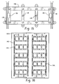
- FIGURES 31A and 31B show a top view 500 and bottom view 502 of a PCB assembly 508 utilized in the lattice LED panel 104L.
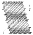
- FIGURE 32 shows a top view of a plurality of lattice LED panels 104L as illustrated in FIGURE 12 above.
- FIGURE 33A illustrates a top view and FIGURE 33B illustrates a bottom of view of the over mold 122.
- FIGURE 33C illustrates an exploded view of the over mold 122 with the PCB assembly 508 and the flexible strips 126.
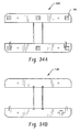
- FIGURES 34A and 34B illustrate top and bottom views 520 and 530 of the PCB assembly 508 shown in FIGURES 31A and 31B above.
- one power supply 144 may be used to supply the power to one (1) or more columns of panels through the use of splice connectors 146.
- IDCs 136 and quick connect wires 148 may be used between the columns to deliver power from one column of panels 104L to the next panel 104L, as depicted in FIGURE 18 .
- current is carried on both sides of panel 104L.
- current may be carried on only one side of panel 104L and IDC 136 may be located on the side of panel 104L which carries the current for delivering power to another column of panels 104L.
- a flexible strip 162 may be attached to the other side of panel 104L for support as shown in FIGURE 19 .
- the wire between adjacent panels may be soldered to each panel.
- combinations of IDCs and soldering may be used.
- power may be supplied to both sides of panel 104L as shown in FIGURE 15 .
- Panel 104L in FIGURE 15 may include one or more IDCs 136.
- a further optional feature is mounting points 138, if mounting of panel 104L is desired for the particular application.
- a single power supply may be used to supply power to a sufficient amount of columns or rows of panels 104 to illuminate up to about twenty (20) square feet (ft 2 ) [1.86m 2 ] of surface area of a sign face. It is further preferred that the power source is used to provide power to at least about fourteen (14) square feet (ft 2 ) [1.30m 2 ] of surface area of a sign face.
- the examples for a backlight system described herein are applicable to both of 12V and 24V systems.
- system 100 may operate as a constant voltage applied to each board, constant current applied to each panel, or constant voltage power source.
- LEDs 106 on panel 104L may be electrically connected together and mounted to panel 104L using a flex circuit or wires.
- the entire panel 104L may be fitted with an over mold 122.
- use of the wires as part of the mechanical support for the system 100 can assist in layout when removing from packaging and when securing to a sign back plate.
- wires can provide trouble-free assembly, by providing a redundant electrical connection to power. For example, one of the two wires can be cut without severing electrical ties, thereby providing additional flexibility in panel placement or rotation for start of a new row.
- Modules can be structured to allow overlapping of panels to provide gaps in material for LEDs from bottom panel to shine through to the face of the cabinet sign.
- System100 may be used in a double sided cabinet signs as depicted in FIGURE 20 and FIGURE 21 .
- FIGURE 20 two (2) columns of panels 104L are mounted back to back. Snap-on connectors may be used to mount the opposing panels 104L back to back.
- opposing panels 104L may be separated by a desired distance D.
- a guide 150 may be used to maintain the location of panels 104L. Variations of guide 150 are illustrated in FIGURES 22A-F .
- guide 150 is depicted as a flat bar applied across all panels 104L in a column of panels.
- guide 150 may consist of two flat bars; one mounted to each end of panels 104L in a particular column of panels 104L.
- FIGURE 22C A third example is shown in FIGURE 22C .
- Guide 150 may consist of two flat bars which are applied to two adjacent panels 104L in a column of panels.
- guide 150 may comprise a bracket.
- the bracket includes a base 152 and two vertical arms 154.
- panel 104L is mounted in a sliding track in each one of arms 154.
- two adjacent panels 104L may be connected together. A first panel is attached along a top section of each of arms 154 of guide 150 and a second panel 104L is attached along base 152 of guide 150.
- Guides 150 may be made out of any suitable material for aligning panels104L. In one example , guides 150 are constructed from plastic. However, other materials of construction may be suitable also. Additionally, guides 150 may be secured to a back plate if desired.
- panel 104L may be formed by connector in between vertically adjacent panels 104R.
- the connector may be an integral piece of one of either of the vertically adjacent panels 104R.
- each panel may include one or more pass throughs to pass a wire from one vertically adjacent panel 104R to another vertically adjacent panel 104R.
- the connector may be a unitary element or a multi-piece unit.
- the connector may include a hinge such that between two adjacent panels 104R, a first panel may be moved located in a non-parallel manner to the second panel.
- the system 100 as described above has a particular advantageous application as the lighting system of cabinet sign with a surface area of less than 200 square feet [18.6m 2 ].
- the use of system 100 in the cabinet sign will maximize uniformity and not require the same depth between the sign and the light source as a cabinet sign which uses a fluorescent light source.
- system 100 will decrease sign building costs by reducing installation time of the backlighting system into the cabinet. Also LEDs typically have a much longer life expectancy than fluorescent bulbs which will reduce maintenance costs. Additionally, system 100 is simple to install and it is flexible to accommodate different cabinet sign sizes. In addition to system 100 being adaptable to different sized cabinets, system 100 may be arranged various distances from the sign face of the cabinet sign. Also, system 100 is suitable for those types of cabinet signs having a backing plate for mounting system 100 and for those signs which do not include a backing plate. Accordingly, system 100 is suitable for single sided and double sided cabinet signs.
- panels 104 of system 100 may use series/ parallel architecture. Furthermore, adjacent columns of panels 104 may have the benefit of plug-n-play connections between the columns.
- the plug-n-play connections between the columns may comprise panels 104 including one or both of an insulation displacement connector or one or more butt splices.
- each panel may include two (2) separate series of LED chains.
- each panel may include at least two (2) separate drivers per panel for separate series LED chains, intermixed on the panel. This will have the benefit of the failure of one LED not being noticed on the face of the sign due to the LEDs from each chain being spatially intermixed so that one area of the face of the sign is not significantly impacted.
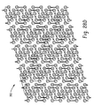
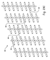
- FIGURES 23 and 24 Depicted in FIGURES 23 and 24 are cabinet signs which include a partial view of the sign face so that the backlighting system for each sign is shown.
- sign 200 includes a single array of panels 104L to illuminate sign face 202.
- the panels 104L are arranged in vertical columns as shown in FIGURE 12 .
- FIGURE 24 includes a double array backlighting system in which panels 104L are arranged as illustrated in FIGURE 14 . If so desired, a double array may be used if it is desired to increase the intensity of the light used to illuminate sign face 202.
- FIGURE 25 is an illustration of a panel 104L which includes a plurality of LEDs 106 and an over mold 122.
- Panel 104L also includes a casing 160 around the exterior edges of panel 104L and over mold 122.
- Backlighting system 100 may be substantially devoid of optics.
- System 100 optionally may not include any of the following items: (1) phosphor panel, (2) a brightness enhancing film, (3) a diffuser, and (4) a light pipe.
- system 100 may not include a fluorescent bulb and/or ballasts.
- System 100 also offers a unique advantage with packaging and storage, in that system 100 may be foldable or rollable at an end user's options. This makes system 100 easy to package and transport to an end user and likewise, system 100 is convenient for the end user to store once it has been delivered.
- a particular example of system 100 may have a cut resolution of no more than about 3, more preferably, no more than about 2, and even more preferably no more than about 1.
- FIGURE 26A illustrates an alternative example , wherein two modules 202 are coupled to a bridge 204 in order to provide flexible lighting systems that have particular desired size and light output.
- the bridge 204 can be constructed of substantially any suitable material such as a plastic or other similar material.
- Each module 202 can be coupled to the bridge 204 via a recessed portion that can accept a mechanical tab connecter or equivalent from the bridge.
- the bridge can include electrical connectors in order to facilitate delivery of power and/or electrical control signals to the modules 202.
- the bridge can include a connector 212 to accommodate an additional module.
- Each module 202 includes a plurality of LEDs 203. In one representative embodiment, three LEDs are included for with each module 202.
- the LEDs 203 can be spaced apart a predetermined distance such that a fixed number of LEDs 203 are based in part upon the length of the modules 202. Since each module is detachable from the bridge 204, the lighting system can easily be deconstructed and packaged for transport.
- Power can be delivered to the LEDs 203 on the modules 202 utilizing an end cap power input plug 206.
- the end cap power input plug 206 can be a male component and coupled to the module via a female power input connector 208.
- the power input plug 206 includes electrical contacts that are coupled to the female connector 208 to deliver power when the power input plug 206 is plugged in. In this manner, once the modules 202 have been mounted in a particular location, power can be delivered via the connection between the power input plug 206 and the female connector 208.
- modules 202 can be coupled to an additional module 209 via a modular power throughput port 210.
- FIGURE 26B illustrates the connection between the module 202 and the module 209 via the modular power throughput port 210 and corresponding female power input connector 208 located on the module 209.
- the modular power throughput port 210 is located on the opposite side of the module 202 as the external power input. It is to be appreciated, however, that the modular power throughput port 210 can be located in substantially any location on the module 202.
- the location of the modular power throughput port 210 can be related to a desired configuration of the modules 202 in relation to one another. Allowing flexible connectivity between modules by providing associated power connectors in convenient locations facilitates flexible design and manufacture of various desired illumination elements.
- FIGURE 26C illustrates how a second array 214 can be coupled to the bridge 204 via the connector 212.
- the FIGURE 26D illustrates a single array illumination system 220 that is created utilizing a plurality of modules 202 and bridges 204 as shown in FIGURE 26A .
- FIGURE 26E illustrates a double array illumination system 224.
- the illumination system 224 is created by coupling a plurality of second arrays 214 to a plurality of respective connectors 212.
- FIGURE 27A illustrates an interlocking LED panel 230 that facilitates a single or a double array of modules.
- the interlocking panel 230 includes a plurality of recesses 232, 234, 236, 238, 240, 242, and 244 that can accommodate a disparate interlocking module to provide additional light output for a system.
- Each recess 232-244 can include one or more connectors that protrude from the surface of each recess of the LED panel 230 and are seated in the back of an LED panel which is stacked on top.
- One LED is located on each raised form 246, 248, 250, 252, 254, and 256.
- Power is provided to the interlocking panel 230 via power lines 260 and 262 located on either side of the panel 230 as described above in FIGURE 12 . It is to be appreciated that the LEDs can be spaced apart substantially any distance from each other and that such spacing may not be uniform throughout the panel.
- FIGURE 27B shows a single array lighting system 270 that employs a plurality of interlocking LED panels 230.
- the lighting system 270 includes five columns wherein each column includes four interlocking panels 230. Power from each column is distributed via a power connector 272, 274, 276, and 278. In this manner, a plurality of panels can be connected in substantially any configuration.
- FIGURE 27C illustrates a lighting system 280 that includes a double array of interlocking LED panels 230.
- a second set of LED panels is stacked on top of the first set such that the back of the top LED panels is coupled to the bottom set of LED panels via connectors located on the surface of each recess 232-244.
- the double array system 280 is very similar to the single array system 270 in terms of connectivity.
- the system 280 also includes a second set of LED panels 230 that are placed in the recesses 232-244 of the single array system 270.
- Power for the second set of LED panels can be provided via two power lines 260 and 262. In one approach, power is provided via the connectors from the bottom set of LED panels to the top set of LED panels so that the top set of panels does not require power lines to be connected therewith.
- FIGURE 28A illustrates an I-shaped LED panel 290 that includes a first arm 310 and a second arm 312 positioned in parallel to one another and connected by a cross member 314.
- the first arm 310 includes three LEDs and two connectors 292 and 294.
- the second arm 312 includes three LEDs and two connectors 292 and 294.
- the first arm 310 and the second arm 312 are connected via the bridge 314 which includes a connector 300.
- the connectors can be employed to allow stacking of the I-shaped LED panels 290 to provide a double array of LED panels for a desired lighting system configuration.
- the connectors are a protrusion from the surface of the I-shaped LED panel which is seated in corresponding dimples in the back of LED panels stacked on top thereof.
- FIGURE 28B shows an alternate example wherein power is delivered to the I-shaped LED panel 290 via power lines 306 and 308.
- the first arm 310 and the second arm 312 are connected via the power lines 306 and 308 respectively.
- power can be delivered to top LED panels in a double array configuration via the connectors 292-300.
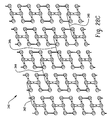
- FIGURE 28C illustrates a single array lighting system 340 that includes a plurality of I-shaped LED panels 290.
- the single array lighting system 340 includes five columns of I-shaped LED panels wherein each column includes four I-shaped LED panels. It is to be appreciated that substantially any number of LED panels can be configured in substantially any manner.
- Each column of I-shaped LED panels is connected via coupling lines 342, 344, 346, and 348.
- the coupling lines 342-348 can be employed to provide power and/or control signals from one group of I-shaped LED panels to another.
- FIGURE 28D illustrates a double array lighting system 350 that includes the single array of lighting system 340 with an additional array of I-shaped light elements stacked on top therewith. As discussed above, the second top array can be coupled to the bottom array via connectors 292-300.
- FIGURE 29A illustrates an H-shaped LED panel 360.
- the LED panel 360 includes a first arm 362, a second arm 364 and a third arm 366.
- the first arm 362 and the second arm 364 are parallel to one another and are connected via the third arm 366 which is oriented perpendicular to the first and second arms 362 and 364.
- the first arm includes three LEDs and connectors 366 and 368.
- the second arm includes three LEDs and connectors 370 and 372.
- the third arm 366 includes a connecter 374 that is located between the first arm 362 and the second arm 364.
- the third arm 366 can include one or more power lines that are located within the body of the arm.
- the bottom of the third arm 366 can include a male power connector 376.
- the top of the third arm 366 can include a female power receptacle 378.
- the H-shaped LED panel can be coupled to one or more disparate H-shaped LED panels via the male and female power connectors wherein power is delivered to all the LED panels.
- power delivery is illustrated in FIGURE 29B . It is to be appreciated that although power delivered via the third arm 366, substantially any signal can be communicated.
- One example can be a control signal utilizing a particular communication protocol.
- FIGURE 29C illustrates a single array lighting system 380 that includes a plurality of H-shaped LED panels 360.
- the single array lighting system 380 includes five columns of H-shaped LED panels wherein each column includes four H-shaped LED panels. It is to be appreciated that substantially any number of LED panels can be configured in substantially any manner.
- Each column of H-shaped LED panels is connected via coupling lines 382, 384, 386, and 388.
- the coupling lines 382-388 can be employed to provide power and/or control signals from one group of H-shaped LED panels to another.
- FIGURE 29D illustrates a double array lighting system 390 that includes the single array of lighting system 380 with an additional array of H-shaped light elements stacked on top therewith.
- the second top array can be coupled to the bottom array via connectors 366-374.
- the lighting systems 380 and 390 can be broken down into single LED panels to facilitate compact transport from one location to another.
- FIGURE 30A illustrates two modules 400 and 402 which each include three LEDs. Each module is comprised of three pods (one for each LED) on a single axis wherein an arm connects each pod to the one adjacent.
- Module 400 includes a male hinge component 404 on a first side of the module and a female hinge component 406 on a second side. The middle pod accommodates a power line 408.
- Module 400 is coupled to module 402 via the male and female hinge components 404 and 406 of module 400 to the corresponding female and male hinge components of module 402.
- Connectors 410 and 412 are employed to facilitate a double array lighting system wherein a second set of LED modules is stacked on top of a first set and coupled mechanically thereto.
- FIGURE 30B illustrates folding two a plurality of modules together to provide a more compact footprint for transport. Such folding is facilitated via the hinges to couple two or more modules together.
- FIGURE 30C illustrates a single array lighting system 420 that includes a plurality of LED modules 400.
- the single array lighting system 420 includes five columns of LED modules wherein each column includes four LED modules. It is to be appreciated that substantially any number of LED modules can be configured in substantially any manner.
- FIGURE 30D illustrates a double array lighting system 440 that includes the single array of lighting system 420 with an additional array of LED modules stacked on top therewith. The second top array can be coupled to the bottom array via connectors 410 and 412.
- the lighting systems 420 and 440 can be broken down into single LED modules to facilitate compact transport from one location to another.
Landscapes
- Physics & Mathematics (AREA)
- General Physics & Mathematics (AREA)
- Engineering & Computer Science (AREA)
- Theoretical Computer Science (AREA)
- Illuminated Signs And Luminous Advertising (AREA)
- Non-Portable Lighting Devices Or Systems Thereof (AREA)
- Fastening Of Light Sources Or Lamp Holders (AREA)
- Arrangement Of Elements, Cooling, Sealing, Or The Like Of Lighting Devices (AREA)
Claims (15)
- Système de rétroéclairage (100) pour enseignecaisson comprenant :une enceinte comportant une face d'enseigne frontale et une section arrière ;une pluralité de panneaux, chaque panneau (104) comportant :etune pluralité de diodes électroluminescentes ("DEL") (106) attachées au panneau, dans lequel la distance entre chaque DEL et la face d'enseigne de l'enceinte divisée par la distance entre cette même DEL et l'une des DEL adjacentes la plus proche fournit un rapport de moins de 1,4, etun circuit intégré (108) ;
un fil métallique, le fil métallique connectant des panneaux adjacents et
caractérisé en ce que la pluralité de panneaux est attachée à chacun d'un ou de plusieurs rails (110). - Système de rétroéclairage (100) selon la revendication 1 dans lequel chaque panneau (104) comprend une carte à câblage imprimé.
- Système de rétroéclairage (100) selon la revendication 2 dans lequel la carte à câblage imprimé comprend au moins l'une d'une carte à circuit imprimé, d'une carte à circuit imprimé métallisé, et d'un circuit souple.
- Système de rétroéclairage (100) selon l'une quelconque des revendications susmentionnées dans lequel les DEL (106) sont équidistantes.
- Système de rétroéclairage (100) selon l'une quelconque des revendications susmentionnées comprenant en outre un surmoule attaché à un panneau, le surmoule (122) étant destiné à être placé entre la DEL (106) et une surface frontale de l'enseigne.
- Système de rétroéclairage (100) selon la revendication 5 dans lequel une surface supérieure du surmoule (122) est construite en un matériau transparent résistant aux intempéries.
- Système de rétroéclairage (100) selon l'une quelconque des revendications susmentionnées dans lequel les DEL (106) sont agencées dans une orientation bidimensionnelle.
- Système de rétroéclairage (100) selon l'une quelconque des revendications susmentionnées comprenant en outre chaque DEL (106) dotée d'un élément de protection aligné pour protéger la diode de chaque DEL contre tout contact physique.
- Système de rétroéclairage (100) selon l'une quelconque des revendications susmentionnées dans lequel une luminosité de la lumière émise par les DEL (106) sur un panneau (104) comprend jusqu'à 1500 candela par mètre carré mesurée au niveau de la surface extérieure d'une face d'enseigne d'une enseigne-caisson.
- Système de rétroéclairage (100) selon l'une quelconque des revendications susmentionnées dans lequel les fils métalliques définissent l'espacement relatif des diodes électroluminescentes entre des panneaux adjacents (104).
- Système de rétroéclairage (100) selon l'une quelconque des revendications susmentionnées dans lequel la distance entre chaque DEL (106) et une face d'enseigne du caisson divisée par la distance entre cette même DEL et la DEL adjacente la plus proche fournit un rapport de 1,25 à 0,5.
- Système de rétroéclairage (100) selon l'une quelconque des revendications susmentionnées comprenant en outre une ou plusieurs bornes sur chaque panneau (104) destinées à la connexion de deux panneaux adjacents ensemble.
- Système de rétroéclairage selon la revendication 1, dans lequel les panneaux sont supportés de manière ajustable sur les un ou plusieurs rails (110).
- Système de rétroéclairage selon la revendication 1, dans lequel les un ou plusieurs rails (110) sont construits en un matériau pouvant faire office de dissipateur thermique.
- Système de rétroéclairage selon la revendication 1, comportant en outre un cadre (102) interconnectant au moins deux rails (110).
Applications Claiming Priority (3)
| Application Number | Priority Date | Filing Date | Title |
|---|---|---|---|
| US84965306P | 2006-10-05 | 2006-10-05 | |
| US11/784,639 US9564070B2 (en) | 2006-10-05 | 2007-04-09 | LED backlighting system for cabinet sign |
| PCT/US2007/080456 WO2008043025A2 (fr) | 2006-10-05 | 2007-10-04 | Système de rétroéclairage à diodes électroluminescentes pour caisson |
Publications (3)
| Publication Number | Publication Date |
|---|---|
| EP2070071A2 EP2070071A2 (fr) | 2009-06-17 |
| EP2070071A4 EP2070071A4 (fr) | 2011-03-09 |
| EP2070071B1 true EP2070071B1 (fr) | 2016-11-16 |
Family
ID=39269221
Family Applications (1)
| Application Number | Title | Priority Date | Filing Date |
|---|---|---|---|
| EP07843847.0A Not-in-force EP2070071B1 (fr) | 2006-10-05 | 2007-10-04 | Système de rétroéclairage à diodes électroluminescentes pour caisson |
Country Status (4)
| Country | Link |
|---|---|
| EP (1) | EP2070071B1 (fr) |
| CN (4) | CN118898955A (fr) |
| ES (1) | ES2615177T3 (fr) |
| WO (1) | WO2008043025A2 (fr) |
Families Citing this family (12)
| Publication number | Priority date | Publication date | Assignee | Title |
|---|---|---|---|---|
| CA2743007A1 (fr) * | 2008-11-10 | 2010-05-14 | Pix2O Corporation | Affichage a del portable et a grand ecran |
| FR2956239B1 (fr) * | 2010-02-09 | 2012-03-16 | Charvet Ind | Dispositif d'affichage lumineux d'une enseigne |
| US8474998B2 (en) * | 2010-03-08 | 2013-07-02 | Ge Lighting Solutions Llc | Rail and clip mounting for LED modules for fluorescent application replacement |
| AT12555U1 (de) * | 2011-02-25 | 2012-07-15 | Best Systems Gmbh | Leuchtkasten |
| CN102136227B (zh) * | 2011-03-17 | 2015-02-25 | 深圳市中庆微科技开发有限公司 | 一种在线检测led箱体的智能安装连接装置 |
| TWM439816U (en) * | 2012-05-17 | 2012-10-21 | Star Reach Corp | Display module |
| US9195281B2 (en) | 2013-12-31 | 2015-11-24 | Ultravision Technologies, Llc | System and method for a modular multi-panel display |
| US9582237B2 (en) | 2013-12-31 | 2017-02-28 | Ultravision Technologies, Llc | Modular display panels with different pitches |
| DK3091528T3 (da) * | 2015-05-05 | 2020-12-07 | Harman Professional Denmark Aps | Støtteramme til videovæg |
| CN204665178U (zh) * | 2015-05-22 | 2015-09-23 | 深圳金立翔视效科技有限公司 | 一种led灯板组件 |
| CN109386766A (zh) * | 2017-08-14 | 2019-02-26 | 通用电气照明解决方案有限公司 | 照明系统 |
| BE1026256B1 (nl) * | 2018-05-07 | 2019-12-12 | Vivalyte Bvba | Verlichtingsstructuur |
Family Cites Families (26)
| Publication number | Priority date | Publication date | Assignee | Title |
|---|---|---|---|---|
| SE449671B (sv) * | 1985-03-20 | 1987-05-11 | Indel Ab | Skyltanordning avsedd for text- och/eller sifferatergivning utomhus |
| US5778577A (en) * | 1996-06-14 | 1998-07-14 | Bailey; James David | Changeable numeric signs |
| US5900850A (en) * | 1996-08-28 | 1999-05-04 | Bailey; James Tam | Portable large scale image display system |
| US5838247A (en) * | 1997-04-01 | 1998-11-17 | Bladowski; Witold S. | Solid state light system |
| US5896688A (en) * | 1997-05-09 | 1999-04-27 | Milwaukee Sign Co., Inc. | Scrolling sign with manually operated change mechanism |
| CA2230173A1 (fr) * | 1998-02-23 | 1999-08-23 | Frederick Dimmick | Enseigne modulaire illuminee ayant des modules ajustables a relachement rapide |
| CN2348246Y (zh) * | 1998-09-14 | 1999-11-10 | 光磊科技股份有限公司 | 复合式发光二极管灯具 |
| US6380865B1 (en) * | 1999-04-06 | 2002-04-30 | 911 Emergency Products, Inc. | Replacement led lamp assembly and modulated power intensity for light source |
| US6505956B1 (en) * | 2000-12-22 | 2003-01-14 | Lektron Industrial Supply, Inc. | Reeled L.E.D. assembly |
| US6558021B2 (en) * | 2001-08-10 | 2003-05-06 | Leotek Electronics Corporation | Light emitting diode modules for illuminated signs |
| KR20040019640A (ko) * | 2002-08-28 | 2004-03-06 | 주식회사 대한전광 | 발광다이오드 전광판 |
| JP4296780B2 (ja) * | 2002-12-27 | 2009-07-15 | ソニー株式会社 | 画像表示デバイス、画像信号処理装置、画像信号処理方法、およびその方法を実行するためのプログラム |
| RU2319063C2 (ru) * | 2003-05-02 | 2008-03-10 | Аваилвс Корпорейшн | Структура светоизлучающего поверхностного тела |
| CN2624047Y (zh) * | 2003-06-18 | 2004-07-07 | 樊邦弘 | 一种可折叠式屏幕灯 |
| US20040262472A1 (en) * | 2003-06-30 | 2004-12-30 | James Thomas | Angled mounting assembly for an LED cluster |
| US7245279B2 (en) | 2003-12-04 | 2007-07-17 | Xiao-Ping Wang | Linear led array |
| ATE370492T1 (de) * | 2004-02-20 | 2007-09-15 | France Telecom | Strukturen mit variablen abmessungen für flexible ledanzeigevorrichtung |
| US7114841B2 (en) | 2004-03-22 | 2006-10-03 | Gelcore Llc | Parallel/series LED strip |
| CN100466306C (zh) * | 2004-04-01 | 2009-03-04 | 林原 | 全彩挠性发光灯条装置 |
| US7241031B2 (en) * | 2004-04-14 | 2007-07-10 | Sloanled, Inc. | Channel letter lighting system using high output white light emitting diodes |
| CN2755713Y (zh) * | 2004-07-22 | 2006-02-01 | 朱建新 | 发光二极管柔性显示屏 |
| KR200366270Y1 (ko) * | 2004-07-23 | 2004-11-04 | 손혁준 | 이중으로 구성된 발광다이오드 화소 모듈 장치 |
| US7273300B2 (en) * | 2004-08-06 | 2007-09-25 | Lumination Llc | Curvilinear LED light source |
| KR101095637B1 (ko) * | 2004-09-23 | 2011-12-19 | 삼성전자주식회사 | 광 발생 장치, 이를 갖는 백라이트 어셈블리 및 백라이트어셈블리를 갖는 표시장치 |
| US20060077669A1 (en) * | 2004-10-07 | 2006-04-13 | Robbie Thielemans | Display element and mechanical mounting interface used therein |
| CN2817061Y (zh) * | 2005-03-18 | 2006-09-13 | 广东雪莱特光电科技股份有限公司 | 一种新型超紧凑型平面光源 |
-
2007
- 2007-10-04 CN CN202411316123.6A patent/CN118898955A/zh active Pending
- 2007-10-04 CN CN201810249559.6A patent/CN108492726A/zh active Pending
- 2007-10-04 CN CN200780041886.2A patent/CN101536066B/zh not_active Expired - Fee Related
- 2007-10-04 EP EP07843847.0A patent/EP2070071B1/fr not_active Not-in-force
- 2007-10-04 ES ES07843847.0T patent/ES2615177T3/es active Active
- 2007-10-04 CN CN201410099341.9A patent/CN104269112B/zh not_active Expired - Fee Related
- 2007-10-04 WO PCT/US2007/080456 patent/WO2008043025A2/fr not_active Ceased
Also Published As
| Publication number | Publication date |
|---|---|
| CN104269112B (zh) | 2018-06-08 |
| ES2615177T3 (es) | 2017-06-05 |
| CN101536066A (zh) | 2009-09-16 |
| WO2008043025A2 (fr) | 2008-04-10 |
| EP2070071A2 (fr) | 2009-06-17 |
| CN101536066B (zh) | 2014-04-16 |
| CN118898955A (zh) | 2024-11-05 |
| EP2070071A4 (fr) | 2011-03-09 |
| WO2008043025A3 (fr) | 2008-11-20 |
| CN104269112A (zh) | 2015-01-07 |
| CN108492726A (zh) | 2018-09-04 |
Similar Documents
| Publication | Publication Date | Title |
|---|---|---|
| US9836999B2 (en) | LED backlight system for cabinet sign | |
| CN104269112B (zh) | 用于箱体标牌的led背光系统 | |
| US11647572B2 (en) | Lighting systems incorporating connections for signal and power transmission | |
| US7470055B2 (en) | Mounting structure for LED lighting systems | |
| US9170000B2 (en) | Angled emitter channel letter lighting | |
| EP2454520B1 (fr) | Bande lumineuse | |
| US9080745B2 (en) | Angled emitter channel letter lighting | |
| US7213941B2 (en) | Flexible perimeter lighting apparatus | |
| MX2010006500A (es) | Pantalla de diodo emisor de luz a gran escala. | |
| US11396999B2 (en) | Sealed and sealable scalable lighting systems incorporating flexible light sheets and related methods | |
| US10665139B2 (en) | LED matrix lighting device | |
| EP2973521B1 (fr) | Système d'éclairage de boîte de signalisation | |
| US20110127931A1 (en) | Light source device and illumination apparatus | |
| US20110194284A1 (en) | Channel letter lighting system using high output white light emitting diodes | |
| JP2007109447A (ja) | 面状照明光源 | |
| EP2976568A2 (fr) | Système d'éclairage à boîte de lumière en angle | |
| CN2793546Y (zh) | 带有发光元件的挠性基片及其固定用的系列组合配件 | |
| JP6148382B2 (ja) | 発光装置および照明装置 | |
| KR20090001816U (ko) | 분리가능한 엘이디모듈 |
Legal Events
| Date | Code | Title | Description |
|---|---|---|---|
| PUAI | Public reference made under article 153(3) epc to a published international application that has entered the european phase |
Free format text: ORIGINAL CODE: 0009012 |
|
| 17P | Request for examination filed |
Effective date: 20090409 |
|
| AK | Designated contracting states |
Kind code of ref document: A2 Designated state(s): AT BE BG CH CY CZ DE DK EE ES FI FR GB GR HU IE IS IT LI LT LU LV MC MT NL PL PT RO SE SI SK TR |
|
| AX | Request for extension of the european patent |
Extension state: AL BA HR MK RS |
|
| DAX | Request for extension of the european patent (deleted) | ||
| A4 | Supplementary search report drawn up and despatched |
Effective date: 20110203 |
|
| RAP1 | Party data changed (applicant data changed or rights of an application transferred) |
Owner name: GE LIGHTING SOLUTIONS, LLC |
|
| 17Q | First examination report despatched |
Effective date: 20111207 |
|
| REG | Reference to a national code |
Ref country code: DE Ref legal event code: R079 Ref document number: 602007048810 Country of ref document: DE Free format text: PREVIOUS MAIN CLASS: G09F0013040000 Ipc: G09F0009330000 |
|
| GRAP | Despatch of communication of intention to grant a patent |
Free format text: ORIGINAL CODE: EPIDOSNIGR1 |
|
| RIC1 | Information provided on ipc code assigned before grant |
Ipc: G09F 9/33 20060101AFI20160510BHEP Ipc: G09F 13/22 20060101ALI20160510BHEP |
|
| INTG | Intention to grant announced |
Effective date: 20160608 |
|
| GRAS | Grant fee paid |
Free format text: ORIGINAL CODE: EPIDOSNIGR3 |
|
| GRAA | (expected) grant |
Free format text: ORIGINAL CODE: 0009210 |
|
| AK | Designated contracting states |
Kind code of ref document: B1 Designated state(s): AT BE BG CH CY CZ DE DK EE ES FI FR GB GR HU IE IS IT LI LT LU LV MC MT NL PL PT RO SE SI SK TR |
|
| REG | Reference to a national code |
Ref country code: GB Ref legal event code: FG4D |
|
| REG | Reference to a national code |
Ref country code: CH Ref legal event code: EP |
|
| REG | Reference to a national code |
Ref country code: IE Ref legal event code: FG4D |
|
| REG | Reference to a national code |
Ref country code: AT Ref legal event code: REF Ref document number: 846571 Country of ref document: AT Kind code of ref document: T Effective date: 20161215 |
|
| REG | Reference to a national code |
Ref country code: DE Ref legal event code: R096 Ref document number: 602007048810 Country of ref document: DE |
|
| PG25 | Lapsed in a contracting state [announced via postgrant information from national office to epo] |
Ref country code: LV Free format text: LAPSE BECAUSE OF FAILURE TO SUBMIT A TRANSLATION OF THE DESCRIPTION OR TO PAY THE FEE WITHIN THE PRESCRIBED TIME-LIMIT Effective date: 20161116 |
|
| REG | Reference to a national code |
Ref country code: NL Ref legal event code: MP Effective date: 20161116 |
|
| REG | Reference to a national code |
Ref country code: LT Ref legal event code: MG4D |
|
| REG | Reference to a national code |
Ref country code: AT Ref legal event code: MK05 Ref document number: 846571 Country of ref document: AT Kind code of ref document: T Effective date: 20161116 |
|
| PG25 | Lapsed in a contracting state [announced via postgrant information from national office to epo] |
Ref country code: SE Free format text: LAPSE BECAUSE OF FAILURE TO SUBMIT A TRANSLATION OF THE DESCRIPTION OR TO PAY THE FEE WITHIN THE PRESCRIBED TIME-LIMIT Effective date: 20161116 Ref country code: LT Free format text: LAPSE BECAUSE OF FAILURE TO SUBMIT A TRANSLATION OF THE DESCRIPTION OR TO PAY THE FEE WITHIN THE PRESCRIBED TIME-LIMIT Effective date: 20161116 Ref country code: GR Free format text: LAPSE BECAUSE OF FAILURE TO SUBMIT A TRANSLATION OF THE DESCRIPTION OR TO PAY THE FEE WITHIN THE PRESCRIBED TIME-LIMIT Effective date: 20170217 Ref country code: NL Free format text: LAPSE BECAUSE OF FAILURE TO SUBMIT A TRANSLATION OF THE DESCRIPTION OR TO PAY THE FEE WITHIN THE PRESCRIBED TIME-LIMIT Effective date: 20161116 |
|
| PG25 | Lapsed in a contracting state [announced via postgrant information from national office to epo] |
Ref country code: PL Free format text: LAPSE BECAUSE OF FAILURE TO SUBMIT A TRANSLATION OF THE DESCRIPTION OR TO PAY THE FEE WITHIN THE PRESCRIBED TIME-LIMIT Effective date: 20161116 Ref country code: PT Free format text: LAPSE BECAUSE OF FAILURE TO SUBMIT A TRANSLATION OF THE DESCRIPTION OR TO PAY THE FEE WITHIN THE PRESCRIBED TIME-LIMIT Effective date: 20170316 Ref country code: FI Free format text: LAPSE BECAUSE OF FAILURE TO SUBMIT A TRANSLATION OF THE DESCRIPTION OR TO PAY THE FEE WITHIN THE PRESCRIBED TIME-LIMIT Effective date: 20161116 Ref country code: AT Free format text: LAPSE BECAUSE OF FAILURE TO SUBMIT A TRANSLATION OF THE DESCRIPTION OR TO PAY THE FEE WITHIN THE PRESCRIBED TIME-LIMIT Effective date: 20161116 |
|
| REG | Reference to a national code |
Ref country code: ES Ref legal event code: FG2A Ref document number: 2615177 Country of ref document: ES Kind code of ref document: T3 Effective date: 20170605 |
|
| PG25 | Lapsed in a contracting state [announced via postgrant information from national office to epo] |
Ref country code: DK Free format text: LAPSE BECAUSE OF FAILURE TO SUBMIT A TRANSLATION OF THE DESCRIPTION OR TO PAY THE FEE WITHIN THE PRESCRIBED TIME-LIMIT Effective date: 20161116 Ref country code: CZ Free format text: LAPSE BECAUSE OF FAILURE TO SUBMIT A TRANSLATION OF THE DESCRIPTION OR TO PAY THE FEE WITHIN THE PRESCRIBED TIME-LIMIT Effective date: 20161116 Ref country code: SK Free format text: LAPSE BECAUSE OF FAILURE TO SUBMIT A TRANSLATION OF THE DESCRIPTION OR TO PAY THE FEE WITHIN THE PRESCRIBED TIME-LIMIT Effective date: 20161116 Ref country code: RO Free format text: LAPSE BECAUSE OF FAILURE TO SUBMIT A TRANSLATION OF THE DESCRIPTION OR TO PAY THE FEE WITHIN THE PRESCRIBED TIME-LIMIT Effective date: 20161116 Ref country code: EE Free format text: LAPSE BECAUSE OF FAILURE TO SUBMIT A TRANSLATION OF THE DESCRIPTION OR TO PAY THE FEE WITHIN THE PRESCRIBED TIME-LIMIT Effective date: 20161116 |
|
| REG | Reference to a national code |
Ref country code: DE Ref legal event code: R097 Ref document number: 602007048810 Country of ref document: DE |
|
| PG25 | Lapsed in a contracting state [announced via postgrant information from national office to epo] |
Ref country code: BG Free format text: LAPSE BECAUSE OF FAILURE TO SUBMIT A TRANSLATION OF THE DESCRIPTION OR TO PAY THE FEE WITHIN THE PRESCRIBED TIME-LIMIT Effective date: 20170216 Ref country code: BE Free format text: LAPSE BECAUSE OF FAILURE TO SUBMIT A TRANSLATION OF THE DESCRIPTION OR TO PAY THE FEE WITHIN THE PRESCRIBED TIME-LIMIT Effective date: 20161116 |
|
| PLBE | No opposition filed within time limit |
Free format text: ORIGINAL CODE: 0009261 |
|
| STAA | Information on the status of an ep patent application or granted ep patent |
Free format text: STATUS: NO OPPOSITION FILED WITHIN TIME LIMIT |
|
| 26N | No opposition filed |
Effective date: 20170817 |
|
| REG | Reference to a national code |
Ref country code: FR Ref legal event code: PLFP Year of fee payment: 11 |
|
| PG25 | Lapsed in a contracting state [announced via postgrant information from national office to epo] |
Ref country code: SI Free format text: LAPSE BECAUSE OF FAILURE TO SUBMIT A TRANSLATION OF THE DESCRIPTION OR TO PAY THE FEE WITHIN THE PRESCRIBED TIME-LIMIT Effective date: 20161116 |
|
| PG25 | Lapsed in a contracting state [announced via postgrant information from national office to epo] |
Ref country code: MC Free format text: LAPSE BECAUSE OF FAILURE TO SUBMIT A TRANSLATION OF THE DESCRIPTION OR TO PAY THE FEE WITHIN THE PRESCRIBED TIME-LIMIT Effective date: 20161116 |
|
| REG | Reference to a national code |
Ref country code: CH Ref legal event code: PL |
|
| REG | Reference to a national code |
Ref country code: IE Ref legal event code: MM4A |
|
| PG25 | Lapsed in a contracting state [announced via postgrant information from national office to epo] |
Ref country code: LI Free format text: LAPSE BECAUSE OF NON-PAYMENT OF DUE FEES Effective date: 20171031 Ref country code: LU Free format text: LAPSE BECAUSE OF NON-PAYMENT OF DUE FEES Effective date: 20171004 Ref country code: CH Free format text: LAPSE BECAUSE OF NON-PAYMENT OF DUE FEES Effective date: 20171031 |
|
| REG | Reference to a national code |
Ref country code: FR Ref legal event code: PLFP Year of fee payment: 12 |
|
| PG25 | Lapsed in a contracting state [announced via postgrant information from national office to epo] |
Ref country code: MT Free format text: LAPSE BECAUSE OF NON-PAYMENT OF DUE FEES Effective date: 20171004 |
|
| PG25 | Lapsed in a contracting state [announced via postgrant information from national office to epo] |
Ref country code: IE Free format text: LAPSE BECAUSE OF NON-PAYMENT OF DUE FEES Effective date: 20171004 |
|
| PG25 | Lapsed in a contracting state [announced via postgrant information from national office to epo] |
Ref country code: HU Free format text: LAPSE BECAUSE OF FAILURE TO SUBMIT A TRANSLATION OF THE DESCRIPTION OR TO PAY THE FEE WITHIN THE PRESCRIBED TIME-LIMIT; INVALID AB INITIO Effective date: 20071004 |
|
| PG25 | Lapsed in a contracting state [announced via postgrant information from national office to epo] |
Ref country code: CY Free format text: LAPSE BECAUSE OF NON-PAYMENT OF DUE FEES Effective date: 20161116 |
|
| PG25 | Lapsed in a contracting state [announced via postgrant information from national office to epo] |
Ref country code: TR Free format text: LAPSE BECAUSE OF FAILURE TO SUBMIT A TRANSLATION OF THE DESCRIPTION OR TO PAY THE FEE WITHIN THE PRESCRIBED TIME-LIMIT Effective date: 20161116 |
|
| REG | Reference to a national code |
Ref country code: ES Ref legal event code: PC2A Owner name: CURRENT LIGHTING SOLUTIONS, LLC Effective date: 20200408 |
|
| PG25 | Lapsed in a contracting state [announced via postgrant information from national office to epo] |
Ref country code: IS Free format text: LAPSE BECAUSE OF FAILURE TO SUBMIT A TRANSLATION OF THE DESCRIPTION OR TO PAY THE FEE WITHIN THE PRESCRIBED TIME-LIMIT Effective date: 20170316 |
|
| REG | Reference to a national code |
Ref country code: DE Ref legal event code: R082 Ref document number: 602007048810 Country of ref document: DE Representative=s name: D YOUNG & CO LLP, DE |
|
| PGFP | Annual fee paid to national office [announced via postgrant information from national office to epo] |
Ref country code: GB Payment date: 20200921 Year of fee payment: 14 Ref country code: FR Payment date: 20200917 Year of fee payment: 14 |
|
| PGFP | Annual fee paid to national office [announced via postgrant information from national office to epo] |
Ref country code: DE Payment date: 20200917 Year of fee payment: 14 Ref country code: ES Payment date: 20201102 Year of fee payment: 14 Ref country code: IT Payment date: 20200917 Year of fee payment: 14 |
|
| REG | Reference to a national code |
Ref country code: DE Ref legal event code: R119 Ref document number: 602007048810 Country of ref document: DE |
|
| GBPC | Gb: european patent ceased through non-payment of renewal fee |
Effective date: 20211004 |
|
| PG25 | Lapsed in a contracting state [announced via postgrant information from national office to epo] |
Ref country code: GB Free format text: LAPSE BECAUSE OF NON-PAYMENT OF DUE FEES Effective date: 20211004 Ref country code: DE Free format text: LAPSE BECAUSE OF NON-PAYMENT OF DUE FEES Effective date: 20220503 |
|
| PG25 | Lapsed in a contracting state [announced via postgrant information from national office to epo] |
Ref country code: FR Free format text: LAPSE BECAUSE OF NON-PAYMENT OF DUE FEES Effective date: 20211031 |
|
| PG25 | Lapsed in a contracting state [announced via postgrant information from national office to epo] |
Ref country code: IT Free format text: LAPSE BECAUSE OF NON-PAYMENT OF DUE FEES Effective date: 20211004 |
|
| REG | Reference to a national code |
Ref country code: ES Ref legal event code: FD2A Effective date: 20230202 |
|
| PG25 | Lapsed in a contracting state [announced via postgrant information from national office to epo] |
Ref country code: ES Free format text: LAPSE BECAUSE OF NON-PAYMENT OF DUE FEES Effective date: 20211005 |