EP2070267B1 - Verfahren zur betriebsmittelreservierung in einem lokalen netzwerk, das mehrere subnetze umfasst, entsprechendes computerprogrammprodukt, speichermittel und einrichtung - Google Patents
Verfahren zur betriebsmittelreservierung in einem lokalen netzwerk, das mehrere subnetze umfasst, entsprechendes computerprogrammprodukt, speichermittel und einrichtung Download PDFInfo
- Publication number
- EP2070267B1 EP2070267B1 EP07820169A EP07820169A EP2070267B1 EP 2070267 B1 EP2070267 B1 EP 2070267B1 EP 07820169 A EP07820169 A EP 07820169A EP 07820169 A EP07820169 A EP 07820169A EP 2070267 B1 EP2070267 B1 EP 2070267B1
- Authority
- EP
- European Patent Office
- Prior art keywords
- service
- resource reservation
- subnet
- communications interface
- upnp
- Prior art date
- Legal status (The legal status is an assumption and is not a legal conclusion. Google has not performed a legal analysis and makes no representation as to the accuracy of the status listed.)
- Not-in-force
Links
- 238000000034 method Methods 0.000 title claims abstract description 56
- 238000004590 computer program Methods 0.000 title claims abstract description 4
- 230000005540 biological transmission Effects 0.000 claims abstract description 94
- 238000004891 communication Methods 0.000 claims abstract description 91
- 238000004422 calculation algorithm Methods 0.000 description 33
- 230000004048 modification Effects 0.000 description 19
- 238000012986 modification Methods 0.000 description 19
- 230000009471 action Effects 0.000 description 12
- 238000001514 detection method Methods 0.000 description 10
- 230000004044 response Effects 0.000 description 9
- 238000012545 processing Methods 0.000 description 7
- 238000007726 management method Methods 0.000 description 6
- 230000008859 change Effects 0.000 description 5
- 230000008034 disappearance Effects 0.000 description 4
- 238000004458 analytical method Methods 0.000 description 3
- 230000008901 benefit Effects 0.000 description 3
- 230000008569 process Effects 0.000 description 3
- 230000011664 signaling Effects 0.000 description 3
- 230000006378 damage Effects 0.000 description 2
- 230000007246 mechanism Effects 0.000 description 2
- 239000000344 soap Substances 0.000 description 2
- 238000013519 translation Methods 0.000 description 2
- 101100513046 Neurospora crassa (strain ATCC 24698 / 74-OR23-1A / CBS 708.71 / DSM 1257 / FGSC 987) eth-1 gene Proteins 0.000 description 1
- 230000006399 behavior Effects 0.000 description 1
- 239000000470 constituent Substances 0.000 description 1
- 230000001419 dependent effect Effects 0.000 description 1
- 238000010586 diagram Methods 0.000 description 1
- 230000000694 effects Effects 0.000 description 1
- 238000005516 engineering process Methods 0.000 description 1
- 230000006870 function Effects 0.000 description 1
- 230000003993 interaction Effects 0.000 description 1
- 230000003287 optical effect Effects 0.000 description 1
- 230000000644 propagated effect Effects 0.000 description 1
- 230000001902 propagating effect Effects 0.000 description 1
- 238000013468 resource allocation Methods 0.000 description 1
- 238000012546 transfer Methods 0.000 description 1
Images






Classifications
-
- H—ELECTRICITY
- H04—ELECTRIC COMMUNICATION TECHNIQUE
- H04L—TRANSMISSION OF DIGITAL INFORMATION, e.g. TELEGRAPHIC COMMUNICATION
- H04L47/00—Traffic control in data switching networks
- H04L47/70—Admission control; Resource allocation
- H04L47/72—Admission control; Resource allocation using reservation actions during connection setup
- H04L47/724—Admission control; Resource allocation using reservation actions during connection setup at intermediate nodes, e.g. resource reservation protocol [RSVP]
-
- H—ELECTRICITY
- H04—ELECTRIC COMMUNICATION TECHNIQUE
- H04L—TRANSMISSION OF DIGITAL INFORMATION, e.g. TELEGRAPHIC COMMUNICATION
- H04L47/00—Traffic control in data switching networks
- H04L47/70—Admission control; Resource allocation
-
- H—ELECTRICITY
- H04—ELECTRIC COMMUNICATION TECHNIQUE
- H04L—TRANSMISSION OF DIGITAL INFORMATION, e.g. TELEGRAPHIC COMMUNICATION
- H04L47/00—Traffic control in data switching networks
- H04L47/70—Admission control; Resource allocation
- H04L47/78—Architectures of resource allocation
- H04L47/782—Hierarchical allocation of resources, e.g. involving a hierarchy of local and centralised entities
-
- H—ELECTRICITY
- H04—ELECTRIC COMMUNICATION TECHNIQUE
- H04L—TRANSMISSION OF DIGITAL INFORMATION, e.g. TELEGRAPHIC COMMUNICATION
- H04L47/00—Traffic control in data switching networks
- H04L47/70—Admission control; Resource allocation
- H04L47/82—Miscellaneous aspects
- H04L47/829—Topology based
Definitions
- the field of the invention is that of the transmission of data contents in a communications network.
- the invention relates to the control of the quality of service implemented in transmissions of this kind
- the "Universal Plug and Play” standard (hereinafter designated as the UPnP standard) is aimed at enabling systems and apparatuses to be networked and work together simply and efficiently without preliminary configuration.
- the apparatuses compatible with the UPnP standard are for example audio-video devices and personal computers (PCs) manufactured by various companies. These apparatuses can be integrated into a local IP (Internet Protocol) network such as a home network.
- IP Internet Protocol
- the UPnP standard provides an apparatus compatible with means of dynamic connection to an UPnP network (that implements the UPnP standard), enables it to discover the other compatible apparatuses of the network and enables it to communicate (or set forth) its own capacities.
- the UPnP technology is based on the TCP/IP network protocol, the HTTP (HyperText Transport Protocol) and the XML (Extensible Markup Language) protocol.
- the essential constituents of an UPnP network are the apparatuses, the services offered by these apparatuses and the control points.
- An UPnP apparatus (implementing the UPnP standard) can support several services, and is categorized according to the list of services (for example a video content server type service, a printer type service etc.) that it can provide.
- An UPnP apparatus explains the services that it can implement (referred to hereinafter as "its services") by means of an XML description file.
- a service in an UPnP apparatus comprises a state machine, a control server and an event server.
- the state machine models a state of the service through the updating of state variables characterizing the apparatus.
- the control server receives the requests from remote apparatuses, executes the associated commands and updates the state machine.
- the event server orchestrates the broadcasting of this updating on the network to the UPnP apparatuses that have shown interest in this information.
- An UPnP control point is capable of discovering and controlling UPnP apparatuses of the UPnP network. When a new apparatus is discovered by the control point, it obtains a description of this new apparatus, thus knows the services offered by the apparatus, asks for a precise description of each available service and finally sends requests for the control of the selected service.
- the control point can thus register with the event server in order to be notified of any change in state.
- the "UPnP audiovisual” standard (hereinafter referenced “UPnP AV” standard) defines a set of UPnP apparatuses (for example television sets, VCR machines, DVD players, MP3 players, PCs etc.) with their associated services which are more specifically dedicated to the world of home digital audio/video devices.
- the three main logic entities of an UPnP AV network (which implements the UPnP AV standard) are: a media server having access to multimedia contents which it can broadcast on the local network, a media player or media renderer (capable of locally playing back this type of multimedia contents received from the network) and a control point coordinating the operations.
- the UPnP Quality of Service standard (hereinafter referenced UPnP QoS as described in the referenced document "UPnP QoS standard v1.0/v2.0”) defines a set of UPnP services, relating to quality of service management, that are integrated into UPnP apparatuses. Three services are thus defined:
- QoS Quality of Service
- the UPnP standard relies on the UDP (User Datagram Protocol) multicast protocol for its needs for discovering UPnP apparatuses and services. More specifically, the UPnP standard relies on the SSDP (Simple Service Discovery Protocol) which corresponds to the HTTP-on-UDP protocol whose messages are transmitted in multicast mode towards the address 239.255.255.250 and the port 1900.
- UDP User Datagram Protocol
- SSDP Simple Service Discovery Protocol
- an UPnP control point listens to this address to discover all the apparatuses and services of interest to it.
- the UPnP AV standard assigns the default value 4 to the TTL (Time-to-Live) field, which means that the messages transmitted in multicast mode may cross up to four routers of the local network.
- TTL Time-to-Live
- an UPnP control point may control the stream traveling through 4+1 Ethernet sub-networks (or subnets).
- the UPnP QoS standard is an emerging standard under specification.
- the UPnP QoS standard does not address the problem of the management of "complex" Ethernet networks, namely networks subdivided into several local subnets.
- a QoSManager service in response to a resource reservation request from an UPnP control point, is not capable of addressing a QoS policy (or resource reservation) from end to end for a stream going through several subnets of a local network.
- the invention is aimed inter alia at overcoming these drawbacks of the prior art in at least one of its embodiments.
- the invention in at least one of its embodiments, is also aimed at implementing a technique of this kind that is simple to implement and costs little.
- the invention relates to a method of resource reservation in the context of the transmission of a data content on a transmission path between a source device and a sink device belonging to a communications network, said network comprising a plurality of subnets interconnected by at least one interconnection device possessing at least two communications interfaces connected to said subnets said method being implemented by a higher manager device.
- such a method comprises the following steps:
- the general principle of the invention consists of the creation of at least one representation of service (or service representation) between the subnets of a communications network (implementing a centralized resource reservation protocol) during the transmission of a content on a transmission path.
- representations of service through the receiving of resource reservation requests and their transmission to a higher manager device) enable the implementation of a internal resources reservation to be propagated from one subnet to another subnet on the transmission path.
- the invention provides a technique for the reservation of QoS internal resources from end to end without discontinuity during the transmission of a content on a transmission path going through at least two subnets of a communications network implementing a centralized resource reservation protocol.
- this resource reservation method is compatible with the recommendations of the protocols implemented (such as the QoS, UPnP, UPnP-Av and UPnP-QoS).
- the internal resource reservation step comprises the following steps:
- the resource reservation method also comprises the following steps:
- the method comprises the following step:
- the resource reservation method furthermore comprises the following steps:
- no representation of internal resource reservation service is created for the communications interface of the interconnection device or devices of the subnet comprising the higher manager device.
- the higher manager device carries out the internal resource reservation in its own subnet.
- no representation of internal resource reservation service is declared for the communications interfaces of the interconnection device or devices of the subnet comprising the higher manager device.
- each representation of internal resource reservation service locates the higher manager device by an Anycast type address.
- the creation step is preceded by a step for detection of an appearance of at least one subnet in said network.
- each representation of an internal resource reservation service includes a piece of information for identifying at least one device belonging to a subnet connected to a communications interface of the interconnection device to which the communications interface associated with said service representation belongs and which is distinct from the communications interface associated with said service representation.
- this resource reservation method furthermore comprises the following steps:
- the resource reservation method furthermore comprises the following steps:
- the resource reservation method furthermore comprises the following steps:
- the resource reservation method furthermore comprises a step of destruction of at least one service representation that comprises no identification of a device included in a subnet connected to a communications interface of the interconnection device to which the communications interface associated with said service representation belongs and which is distinct from the communications interface associated with said service representation
- the invention also relates to a computer program product comprising program code instructions for the execution of the steps of the resource reservation methods as described here above, when said program is executed on a computer.
- the invention also relates to a computer-readable storage means storing a set of instructions executable by said computer to implement the resource reservation method as described here above.
- the invention also relates to a higher manager device belonging to a communications network, said network comprising a plurality of sub-networks or subnets interconnected by at least one interconnection device possessing at least two communications interfaces connected to said subnets, said higher manager device comprising means of resource reservation in the context of the transmission of a data content on a transmission path between a source device and a sink device.
- the higher manager device comprises:
- the internal resource reservation means comprise:
- the higher manager device also comprises:
- the higher manager device also comprises:
- the higher manager device also comprises:
- the creation means do not create any representation of internal resource reservation service for the communications interfaces of the interconnection device or devices of the subnet comprising the higher manager device.
- the declaration means do not declare any representation of internal resource reservation service for the communications interfaces of the interconnection device or devices of the subnet comprising the higher manager device.
- each representation of an internal resource reservation service includes means for locating the higher manager device by an Anycast type address.
- the higher manager device comprises means of detection of an appearance of at least one subnet in said network.
- each representation of an internal resource reservation service includes a piece of information for identifying at least one device belonging to a subnet connected to a communications interface of the interconnection device to which the communications interface associated with said service representation belongs and which is distinct from the communications interface associated with said service representation.
- the higher manager device also comprises:
- the higher manager device also comprises:
- the higher manager device also comprises:
- the higher manager device also comprises means of destruction of at least one service representation that comprises no identification of a device included in a subnet connected to a communications interface of the interconnection device to which the communications interface associated with said service representation belongs and which is distinct from the communications interface associated with said service representation
- the centralized signaling protocol may be any protocol other than the UPnP QoS. protocol.
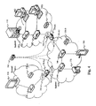
- the local area a network 100 is for example an Ethernet network implementing the IEEE 802 protocol (or any other type of IEEE 802-x type protocol) and enables the implementation of UPnP QoS type communications (at least between certain apparatuses) for which each "UPNP QoS apparatus (or apparatus implementing the UPnP QoS standard) of the network is identified and periodically communicates the description of its services.
- IEEE 802 protocol or any other type of IEEE 802-x type protocol
- the local area network 100 comprises both terminal apparatuses that are visible to the user (for example multimedia terminals of the local area network 100 which are directly controlled by the user) and network infrastructure apparatuses enabling links between these terminal apparatuses.
- the local area network 100 has the particular feature of being constituted by three subnets 100A, 100B, 100C connected together by router devices 130-R1, 130-R2.
- the local area network 100 may be a home network as well as a company local area network, partially or totally constituted by wireless segments, for example compliant with the "Wifi” or “Bluetooth” standards (registered marks).
- the category of terminal apparatuses comprises especially:
- the category of network infrastructure apparatuses includes especially interconnection apparatuses 140 which may be, for example:
- These network infrastructure apparatuses 140 generally implement QoS protocols such as stream priority management protocols (for example the IEEE-802.1p protocol) or Qos online reservation signaling protocols such as the SBM protocol standardized by RFC-2814. They may also implement the UPnP QoS standard.
- QoS protocols such as stream priority management protocols (for example the IEEE-802.1p protocol) or Qos online reservation signaling protocols such as the SBM protocol standardized by RFC-2814. They may also implement the UPnP QoS standard.
- a bridge is a piece of interconnection hardware connecting two Ethernet segments.
- Each of the segments to which a bridge is connected has an associated table of MAC addresses of the terminal apparatuses of this segment which is managed by the bridge.
- Such a table is built by the bridge through a learning process in which, whenever a frame is sent by an apparatus, the bridge stores in the table, the MAC address of the terminal apparatus with respect to the segment concerned.
- a switch is considered to be a bridge having more than two interfaces.
- the category of network infrastructure apparatuses also comprises the router devices 130-R1, 130-R2. These are level 3 selector switch apparatuses hereinafter called "routers".
- a router is a machine having several network boards each connected to a different subnet.
- a router is a device for the interconnection of more than two ethernet segments according to a routing criterion based on the network level 3 (for example source and destination IP addresses).
- routers work through routing tables and routing protocols according to the following model:
- Services compliant with the UPnP QoS standard may be embedded in certain apparatuses of the local area network 100.
- the multimedia stream server 110, customer terminal 120 and UPnP control point 160 have the "UPnP QosDevice" service available to them (here below they shall be designated as QosDevice apparatuses).
- each local area network 100-A, 100-B and 100-C of the local area network 100 comprises a unique "UPnP QoSManager” service, respectively 150-A, 150-B and 150-C hereinafter designated as QoSManager 150-A, 150-B and 150-C (also called manager devices in the resource reservation context).
- QoSManager 150-A, 150-B and 150-C also called manager devices in the resource reservation context.
- These "UPnP QoSManager” services may be embedded in any apparatus preferably having a hardware platform identical to that of the generic apparatus 200 described here below with reference to figure 2 .
- the UPnP QoS standard more specifically defines the procedures to be followed to choose the QosManager that is active if several services are in competition.
- the QosManager services 150-A, 150-B and 150-C are responsible for the local management of the QoS resources in their own subnets, respectively 100-A, 100-B and 100-C. According to the UPnP QoS standard, they are not capable of managing the QoS outside their own subnets.
- the following description relates to the resource reservation method according to the particular embodiment of the invention described here above, in a particular example of the transmission of a multimedia content (or stream) c0 on a transmission path between a source device (multimedia stream server 110) and a sink device (customer terminal 120) belonging to the local area network 100.
- a message for example a message compliant with the UPnP-Av protocol, hereinafter designated as «Avt_SetAvTransportUri» or message 1
- «Avt_SetAvTransportUri» or message 1 compliant with the UPnP protocol is sent to the customer terminal 120 in order to inform its "Media Renderer" service of the type of multimedia content c0 to be received.
- control point 160 asks the QoSManager service 150-B of its subnet 100-B to prepare the QoS resources necessary for the proper routing of the multimedia content c0 between the stream server 110 and a customer terminal 120 (for example by means of a UPnP protocol compliant message hereinafter designated as "QM_RequestTrafficQos" or message 2).
- the QosManager 150-B seeks to obtain the transmission path of c0 through the network in order to determine which are the QosDevice apparatuses to be informed of the reservation of resources to be made for the transmission of the content c0 (message 3).
- the QosManager 150-B will carry out the request from the control point 160, and this control point will authorize the customer terminal 120 to play back the multimedia content c0 (for example by means of a UPnP-Av protocol compliant hereinafter designated as "Avt_Play" or message 4).
- the customer terminal 120 will then send a multimedia stream read request to the stream server 110 (for example an RTSP type message in order to receive the multimedia stream in the RTP broadcast format).
- a multimedia stream read request for example an RTSP type message in order to receive the multimedia stream in the RTP broadcast format.
- the resource reservation method of the invention is implemented in the form of a software program and/or a plurality of software sub-programs (comprising a plurality of algorithms as described here below) which are executed in several machines of the local area network 100, for example in the higher QoSManager 200 (or higher manager device 200) described especially here below with reference to figure 2 .
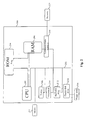
- Figure 2 is a drawing of a higher QoSManager 200 implementing the resource reservation method according to the particular embodiment of the above-mentioned invention.
- the higher QoSManager 200 is indistinguishable from or identified with the QosManager 150-A.
- the higher QoSManager may be identified with any other device of the local network 100 or even a device distinct from any device of the local area network 100 (for example a microcomputer or workstation).
- This higher QoSManager 200 may be connected to any image, video or sound storage means connected to a graphic card and delivering multimedia data to the higher QoSManager 200.
- the higher QoSManager 200 has a communications bus 202 to which the following are connected:
- the higher QoSManager 200 also has the following (but this is optional):
- the communications bus 202 enables communications and interoperability between the different devices included in the higher QoSManager 200 or connected to this apparatus.
- the central processing unit 203 is capable of communicating instructions to any device included in the higher QoSManager 200 directly or by means of any other device of the higher QoSManager 200.
- the executable code of each of the above-mentioned software programs enabling the higher QoSManager 200 to implement the resource reservation method of the invention may be stored for example in the hard disk drive 212 or in the read-only memory 204.
- the central processing unit 203 controls and directs the execution of instructions or portions of software code of the software program or programs according to the invention.
- the software program or programs which are stored in a non-volatile memory for example the hard disk drive 212 or the read-only memory 204 are transferred into the random-access memory 206 which will then contain the executable code of the software program or programs according to the invention, as well as registers to store the variables and parameters necessary for the implementation of the resource reservation method according to the invention.
- Figure 3 is a functional block diagram of the higher QosManager 200 of figure 2 .
- the higher QosManager 200 has network connectivity that possesses software stacks capable of interpreting different network protocols as well as services using the protocols.
- the router devices 130-R1, 130-R2 are interconnection devices used for the routing of information within a local area network consisting of a plurality of subnets.
- the exchange information through routing protocols called IGPs (Interior Gateway Protocols) such as the RIP (Routing Information Protocol) or the OSPF (Open Shortest Path First) protocol.
- IGPs Interior Gateway Protocols
- RIP Raster Information Protocol
- OSPF Open Shortest Path First
- the RIP is incorporated into numerous UNIX operating systems. This is a very simple Distance Vector (Distance Vector Routers work by sending their neighbors the totality of their routing table).
- the routing table is transmitted in RIP packets, packaged in UDP datagrams.
- the port number used is 520.
- RIP packets have a maximum size of 512 bytes. If the routing table to be transmitted is bigger, it is sent in several packets.
- the RIP packets are broadcast.
- the “Link State” technique has been developed to overcome the drawbacks of the "distance vector” technique. To this end, instead of sending their neighbors all the possible destinations, the routers send them packets describing the list of the links to which they are connected, as well as the cost associated with these links. These packets are called “link state packets” (LSP) or “link state advertisements” (LSA). The neighbors that receive these packets transmit them in turn to their neighbors (barring the neighbor that has sent the packet). These packets are sent during certain events such as a change in link state, a cost change or the arrival of a new router.
- LSP link state packets
- LSA link state advertisements
- routers form a database by means of these packets and then compute a total "map" (or topology) of the network from which they can determine the best route from a given source to a given destination (the route for which the sum of the costs is the lowest).
- the routers discover their neighbors by themselves by sending "hello" packets to which the neighbors respond.
- the higher QosManager 200 of the invention implements an IGP routing protocol represented by the block 310.
- IGP routing protocol represented by the block 310.
- OSPF protocol the OSPF protocol because, in this way, a map of the subnet in which the higher QosManager 200 is situated is easier to make.
- the messages received from the subnet are exploited so that the resulting pieces of information are stored locally in a network topology database 304 storing the network topology at level 3.
- the higher QosManager 200 acquires knowledge of a full topology of the local area network 100.
- the block 301 described here below or, without distinction, the database 304 may also comprise an event manager capable of sending internal signals in order to notify the blocks 301-0302 (described here below) of modifications in the network topology.
- UPnP stack 311 is embedded in the higher QosManager 200 in order to support the mechanisms of the invention.
- a first service 301 called "Enhanced QosManager" of the higher QosManager 200 is capable of interfacing with the UPnP stack 311 in order to discover the UPnP QoS services in all the subnets of the local area network 100 (by means of an SSDP interface 312 and of communicating with other QosDevice apparatuses (or apparatuses compatible with the UPnP QoS protocol) using for example a SOAP interface 313.
- the Enhanced QosManager service 301 of the higher QosManager 200 of the invention is also capable of integrating the algorithms of a classic QosManager 150 service as defined by the UPnP QoS standard. This has the effect of proposing a local management of the QoS resources in the subnet in which the higher QosManager 200 is situated.
- a second service 302 called a "Virtual-QosDevice Manager” service is executed by the higher QosManager 200. As described here below (with reference to figure 6 ) this second service 302 is capable of the following:
- the first service 301 and the second service 302 are distinct solely for the purpose of clarifying the description.
- the services may be the same.
- this first service 301 and second service 302 are implemented in object programming language and thus the second service 302 instantiates as many virtual QoS service 305 representation objects as are necessary.
- Each representation of a virtual QosDevice service 305 is perceived by the UPnP QoS devices of the network 100 as being a classic QosDevice service, and is directly accessible according to the UPnP and UPnP QoS protocol through the SSDP description that was given.
- the representations of virtual QosDevice service 305 are created and destroyed, and the corresponding UPnP and SSDP messages are sent to the subnet in which the presence of the virtual service 305 has been declared.
- a UPnP database 303 of the higher QosManager 200 memorizes all the different services and apparatuses compatible with the UPnP protocol in the complete local area network 100.
- this database can be used to obtain lists of machines and associated services according to numerous criteria such as the type of machine (for example a UPnP Av server), the nature of the UPnP QoS services available and the subnet in which this machine is situated.
- This database is enhanced both by the first service 301 and by the second service 302.
- FIG 4 an illustration is provided of the principle of the initialization of the higher QosManager 200 in the local area network 100 according to the particular embodiment of the above-mentioned invention.
- This figure 4 provides a schematic view of the locating of the virtual QosDevice services 305-A1, 305-B1, 305-B2, 305-C1 in the local area network 100. This location is the one perceived by the UPnP QosDevices such as the classic QosManagers 150 following the declaration of the virtual QosDevice services 305 made by the higher QosManager 200.
- the classic QosManager 150-A, 150-B and 150-C detects the presence of the virtual QosDevice services 305-A1, 305-B1, 305-B2, 305-C1 and communicates with them as if they were real QosDevice services present in their own subnet.
- These virtual QosDevice services 305-A1, 305-B1, 305-B2, 305-C1 are however created by the higher QosManager 200 and are physically present in the machine that hosts the higher QosManager 200 as indicated in figure 3 .
- the actions performed by the higher QosManager 200 of the invention when it is started up are presented here below.
- the database 304 When starting up, the database 304 is enhanced upon arrival of information from the local area network 100 by the first service 301.
- An updating (described in detail here below with reference to figure 6 ) is carried out as a background task and an internal notification message may be sent out between the first service 301 and the second service 302 in the event of modifications of the topology (such as replacement of a router, apparatuses becoming inaccessible etc.).
- the second service 302 consults the database 304 to determine the layout of the routers in the local area network 100. Thus, it knows the IP addresses of the apparatuses of each subnet 100-A, 100-B and 100-C, this information being a major criterion for the classification of the UPnP services and machines in the database 303.
- the second service 302 then asks all the UPnP Av apparatuses of the entire network to make themselves known.
- This request is relayed by the SSDP protocol enabling the broadcasting of UPnP datagrams (or messages) of this type.
- the datagrams pass through the router devices 130-R1, 130-R2 and are therefore visible in all the subnets of the local area network 100 (with a maximum of four router devices crossed, which is amply sufficient for the current local area network 100).
- the messages according to the UPnP standards can travel between several subnets. Unlike the UPnP Av standard, the UPnP QoS messages are not directly interpretable outside the subnet from which they are sent, for the information contained in these messages pertains to notions of QoS local to a subnet.
- the datagrams are sent by the UPnP control point 160.
- the TTL value of the IP packets conveying the SSDP messages could be increased in accordance with the number of segments found.
- Appendices 1 and 2 give examples of SSDP messages for the discovery, respectively, of a UPnP-Av server (for example the stream server 110) and a UPnP-Av renderer apparatus (for example a customer terminal 120).
- a UPnP-Av server for example the stream server 110
- a UPnP-Av renderer apparatus for example a customer terminal 120
- these messages are used to obtain the localizing of the UPnP Av apparatuses in the different subnets 100-A, 100-B and 100-C.
- the first service 301 gets to know all the other QosManager services 150-A, 150-B and 150-C available on the local area network 100. Simultaneously with the actions performed by the second service 302, the first service 301 sends SSDP requests on the network by means of the protocol stack 311.
- Appendix 3 gives an example of an SSDP message for the discovery of a QosManager service.
- the database 303 is updated.
- these datagrams are sent out by the UPnP control point 160 which seeks to know the QosManager 150-B in charge of its subnet 100-B and is unaware of the response datagrams coming from the other subnets 100-A and 100-C (IP addressing mask).
- these datagrams are sent out by the higher QosManager 200 in order to obtain knowledge of all the QosManager apparatuses present in the network 100, and the response datagrams coming from the other subnets are therefore not unknown.
- the first service 301 classifies the information received from all the datagrams responding to this interrogation in the base 303.
- the service 302 creates the representations of the virtual QosDevice services 305-A1, 305-B1, 305-B2, 305-C1.
- the representation of a virtual QosDevice 305-A1 is created with the aim of simulating the presence of a QosDevice service present in the communications interface with the subnet 100-A of the interconnection apparatus 130-R2 situated at the boundary between the subnet 100-A and the subnet 100-B.
- This virtual QosDevice service 305-A1 can be described as a bridge used to join together all the UPnP Av apparatuses laid out in the subnets accessible to the router devices 130-R2 by means of the communications services other than the one for which the virtual QosDevice service is associated (such apparatuses are, for example, a UPnP camera 170 of the network 100-B, the stream server 110 or the computers H2 and H3 of the subnet 100-C).
- the description corresponds to the apparatuses of the subnets 100-B and 100-C, which are accessible to the network 100-A through the router 130-R2 by its communications interface with the subnet 100-B.
- Appendix 4 gives an example of an SSDP message for the notification of the presence of the virtual QosDevice service 305-A1.
- the LOCATION field indicates the IP addresses of the apparatus integrating the virtual QosDevice service, in this case the machine hosting the higher QosManager 200.
- this field LOCATION indicates an Anycast IP address instead of the real IP address of the machine hosting the higher QosManager 200 in order to mask its location. This mechanism enables the machine hosting the higher QosManager 200 to receive the messages sent by the classic QosManager 150 which are addressed to a virtual QosDevice service 305.
- the classic QosManager 150 could exclude the virtual QosDevice service 305 from the destination addresses of the QosManager messages since the address of the machine 200 hosting the higher QosManager indicates whether it is situated in a subnet other than the one that is covered by the UPnP QoS standard.
- the Anycast protocol enables unicast transmission between a customer and the closest server identified by the Anycast address (in compliance with the RFC1546 protocol).
- the principle of the Anycast protocol is that the client seeks to communicate with a service (offered by several servers), and it does not matter which server responds to him.
- the network of routers is in charge of delivering the packets to the closest server (the Anycast protocol is supported by the RIP or OSPF routing protocols).
- the URL of the LOCATION field is particularized in order to indicate the one concerned: for example, the string of characters ( «VQD») is added to the basic URL ( « / ») followed by any index whatsoever that can be used to distinguish the virtual QosDevice service.
- the string of characters «VQD»
- the basic URL « / »
- the "GetPathinfonnat ion" request of the UPnP QoS standard is used to obtain information on the QosDevice apparatuses belonging to the transmission path for the content c0 and especially the MAC addresses of these QosDevice apparatuses.
- This type of information is used especially by the local QosManager to determine the transit path for the multimedia stream: all the UPnP QoS apparatuses of this path will then be required to set up a QoS for the stream. It is therefore important to let the classic QosManager 150 believe that the virtual QosDevice service is an apparatus on the path of the content c0, i.e.
- the description of the virtual QosDevice 305 may contain the real IP address of this machine instead of the Anycast address.
- Appendix 5 gives an example of a possible representation of a QosDevice apparatus implementing a bridge function between two Ethernet ports (the first attached to the local segment and the second giving access to the remote UPnP Av apparatuses).
- the field "ReachableMac” lists the MAC addresses of the UPnP Av apparatuses accessible through the link, namely the apparatuses that are not simple interconnection apparatuses.
- the router 130-R2 is considered.
- the link eth0 is connected to a first interface of the router device 130-R2 and the corresponding field "ReachableMac” lists the MAC addresses of the UPnP Av devices of the subnet 100-A, i.e. the device 120.
- the link eth1 is connected to an interface of the router device 130-R2, and the corresponding field "ReachableMac” then lists the MAC addresses of all the other UPnP Av apparatuses laid out in the subnets 100-B and 100-C, i.e. the devices 160, 170, 100, H and H2 should each of them be effectively UPnP Av devices.
- the first service 301 may ask the SSDP stack 312 to send back notifications to it of the presence of QosDevice services in the local area network 100.
- the first service 301 then seeks to classify them in the database 303 according to their membership in their respective subnets, and thus during an interrogation by the "GetPathInformation" action, the field "ReachableMac” could contain the MAC addresses of the QosDevice elements of the subnet or subnets referred to by the current virtual QosDevice service representation.
- the presence of other UPnP Av apparatuses in the subnet 100-B (the representation of the virtual QosDevice service 305-B1 gives the list of the UPnP Av apparatuses of the subnet 100-A; the representation of the virtual QosDevice service 305-B2 gives the list of the UPnP Av apparatuses of the subnet 100-B) and in the subnet 100-C (the representation of the virtual QosDevice service 305-C1 gives the list of the UPnP Av apparatuses of the subnets100-A and 100-B) will be exported in the same way.
- the QosManager service interrogated for the QoS requirements will be that of the higher QosManager 200 and that, through its knowledge of the complete topology of the network 100, it will be capable of contacting each of the classic QosManagers 150 of the other subnets in order to reserve resources for the entire transmission path of the content.
- Figure 5 illustrates the principle of the request for setting up QoS doing the transmission of the content c0 from the stream server 110 to the customer terminal 120 according to the particular embodiment of the invention.
- Figure 5 presents the QoS setup commands received by the higher QosManager 200 of the invention (following the initialization phase described here above with reference to figure 4 ) coming from the QosManager 150-B, and the impact of the actions performed by the higher QosManager 200 following this QoS request.
- the procedure is similar for QoS setup commands coming from the QosManager 150-C.
- the control point 160 decides on a type of multimedia traffic to be communicated between a source device and a sink device.
- the customer terminal 120 and the stream server 110 are situated in two distinct subnets 100-A and 100-C and the control point 160 is situated in a third subnet 100-B.
- any other distribution of the source device, sink device and control point in several subnets of the local area network 100 can be envisaged within the framework of the invention.
- the control point 160 (step 1) asks the QosManager 150-B (which is situated in the same subnet as the control point), in a standardized message "RequestTrafficQoS", to set up a QoS policy for the transmission of the specified multimedia content c0.
- the standardized message "RequestTrafficQos” contains information on the characteristics of the stream c0 as well as the destination (customer terminal 120) and the source (stream server 110).
- the UPnP QoS standard described the XML structure called a "TrafficDescriptor" characterizing the content c0.
- the "TrafficDescriptor" structure described by the UPnP QoS standard comprises two optional fields: "QosBoundarySourceAddress” and "QosBoundaryDestinationAddress”.
- the "QosBoundarySourceAddress" field is dedicated to the case where a content is sent from a terminal situated outside the local area network (or, by extension, outside the subnet of the control point). In this case, the control point must give the IP address of the boundary for the application of QoS in the direction of the source.
- the "QosBoundaryDestinationAddress" field is dedicated to the case where a content is intended for a terminal situated outside the local area network (or, by extension, outside the subnet of the control point). In this case, the control point must give the IP address of the boundary for the application of QoS in the direction of the destination.
- these two fields are used by the QosManager service of the subnet when it takes decisions on the determining of the transmission path taken by the stream and the selection of the QoS apparatuses on this transmission path.
- the principle of the invention is not affected by the presence or absence of these fields when a QoS request is sent from the control point 160.
- the QosManager 150-B will obtain the desired information from the virtual QosDevice apparatuses 305-B1 and 305-B2, whose representations respectively list the device 120 and the device 110.
- the QosManager 150-B tries to find the transmission path for the content c0 which is constituted by QosDevice apparatuses of the subnet 100-B that are present on the transmission path of c0 (for example of the devices 140 of the subnet 100-B).
- the virtual QosDevices 305-B1 and 305-B2 are deemed to form part of the list of these QosDevice apparatuses of the subnet 100-B under the responsibility of the QosManager 150-B.
- step 2 a "SetupTrafficQos" message is sent (step 2) to all the QosDevices concerned (i.e. those belonging to the transmission path) in the subnet, including the virtual QosDevices 305-B1 and 305-B2 generated by the higher QosManager 200.
- This "SetupTrafficQos" message is then received by the virtual QosDevice services 305-B1 and 305-B2 which in turn (step 2A) forward this request internally to the second service 302 of the higher QosManager 200.
- the QosManager 150-A and 150-C services of these subnets 100-A and 100-C are selected and then informed (step 2) in a request ""RequestTrafficQos" of the need for setting up QoS for the multimedia stream.
- the "RequestTrafficQos" request used is of the same type as the one sent by the control point 160 and therefore has a range limited to each subnet.
- the UPnP standard specifies that the RequestTrafficQos request contains for example an indication on the characteristics of the content c0 to be transmitted (XML TrafficDesriptor), which corresponds to those received by the QosManager of the concerned network coming from the control point.
- the "QoSBoundarySourceAddress" and "QosBoundaryDestinationAddress" fields of the TrafficDescriptor structure may be different from those originally proposed by the control point 160. Should the transmission path of the content start outside the concerned subnet, the value specified in the "QosBoundarySourceAddress” field may be the IP address of a router device enabling communication with the source. Should the transmission path of the content end outside the concerned subnet, the value specified in the "QosBoundaryDestinationAddress" field may be the IP address of a router device enabling communication with the destination.
- each QosManager 150-A and 150-C service has the task of locally managing the QoS resources proper to its respective subnet 100-A and 100-C, the QosManager 150-B service having taken responsibility for the management of the subnet 150-B.
- the higher QosManager 200 must avoid redundancy of resource reservations for a same content. Indeed, the QosManagers 150-A and 150-C of these subnets 100-A and 100-C will send a "SetupTrafficQos" request to the virtual QosDevices that have declared themselves on the subnet and are located on the transmission path of the content. The higher QosManager 200 will then have to single out the requests addressed to virtual QosDevices which correspond to subnets already taken into account for reservation of service for the transmission of the content.
- the higher QosManager 200 will make no resource reservations for the requests addressed to virtual QosDevices which represent the apparatuses of the subnet from which the "SetupTrafficQos" request processed in the step 2A was sent, namely the request that initiated the resource reservation procedure in the current subnet.
- the higher QosManager 200 can send back a positive report on execution of the request, even if it has not made the reservation, so that the classic QosManager 150-A or 150-C considers the resource reservation operation on the subnet to have taken place flawlessly.
- a "RequestTrafficQos" request is sent by the control point 160 to the QosManager 150-B to set up data transmission with quality of service from the device 110 to the device 120, respectively situated in the subnets 100-C and 100-A.
- the QosManager 150-B will then send a "SetupTrafficQos" request to the virtual QosDevices that have declared themselves on their subnet 100-B, i.e. the virtual QosDevices 305-B2 and 305-B1. These requests will be interpreted by the higher QosManager 200 which will see to the reservation of resources respectively for the subnets 100-C and 100-A.
- the QosManager 150-C will then contact QosManager 150-C by means of a "RequestTrafficQos" request.
- the QosManager 150-C will send "SetupTrafficQos” requests accordingly on the subnet, one of them addressing the virtual QosDevice 305-C1.
- the virtual QosDevice 305-C1 represents subnets 100-A and 100-B.
- the resource reservation on the subnet 100-A is taken into account by the processing of the "SetupTrafficQos" request addressed to the virtual QosDevice 305-B1 and the resource reservation on the subnet 100-B is taken into account by the QosManager 150-B upon reception of the "RequestTrafficQos" request sent by the control point 160.
- the higher QosManager 200 then ought not to take account of the "SetupTrafficQos" request addressed to the virtual QosDevice 305-C1 in order to avoid redundancy of resource reservation for the transmission of data between the apparatus 110 and the apparatus 120. However, it could send the QosManager 150-C a positive report on execution of the reservation, so that the QosManager 150-C deems the resource reservation operation on its subnet to have taken place flawlessly.
- the resource reservation request according to the invention (which is transparent for the asker) is transmitted from the subnet from where it is sent out to the services compliant with the present invention. These services are then entrusted with propagating the QoS requirements in the other subnets concerned through processing operations specific to the invention performed by the higher QosManager 200.
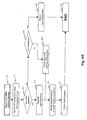
- Figures 6A and 6B present algorithms for updating the topology of the local area network 100 by the higher QosManager 200 according to the particular embodiment of the invention during the reception of routing protocol messages exchanged between the router devices 130-R1 and 130-R2 ( figure 6A ) at the reception the SSDP protocol messages ( figure 6B ).
- a step 600 at the reception of a new message compliant with the IGP routing protocol, the functional block 310, in implementing the IGP routing protocol, informs the network topology database 304 of the reception of this new routing protocol message.
- the higher QosManager 200 records the topology modification indicated in this new message in the network topology database 304.
- Network topology modifications are, for example, the appearance or disappearance of subnets.
- the QosManager 200 verifies the detection of a new subnet from the new message of the routing protocol.
- the UPnP database 303 of the higher QosManager 200 registers the UPnP Av apparatuses and the UPnP QosManager services of this new subnet.
- This architecture of the UPnP 303 database may be one of object orientation, in the sense that an object instance is created for each subnet and linked with two lists of objects, one (the list L2) referencing the UPnP Av apparatuses of the subnet and the other (list L1) referencing QosManager services for this same subnet.
- This database may also be an SQL type structured database possessing several tables (for example one table to identify the subnets, another table for the UPnP Av apparatuses and another table for the QosManager services). Cross-referencing between the tables by means of an appropriate SQL script enables the lists L1 and L2, specified beforehand, to be obtained instantaneously.
- the event manager integrated into the UPnP database 304 informs the second service 302 of the detection of the new subnet in order that this second service 302 may create one or more representations of virtual QosDevice service 305 pertaining to the router devices or devices related to this new subnet.
- the second service 302 also memorizes the association of these virtual QosDevice services 305 with a preliminarily generated identifier of the new subnet.
- the second service 302 asks that each virtual QosDevice 305 should be declared in the network (by means of SSDP notification messages).
- the second service 302 also initiates a search for the UPnP Av apparatuses and QosManager services (SSDP search) to know the UPnP systems of the new subnet.
- SSDP search UPnP Av apparatuses and QosManager services
- the appearance of a subnet in the network 100 enables access to new devices by means of the added interconnection device or devices, the devices becoming accessible by means of the communications interfaces of the interconnection devices already present in the network 100.
- the second service 302 asks that each modified virtual QosDevice service 305 should be declared in the network (by means of SSDP notification messages). Then, in a step 613, the algorithm is ended.
- the higher QosManager 200 checks for the disappearance of a subnet from the new message of the routing protocol.
- the second service 302 identifies the virtual QosDevice services 305 of this subnet and asks them to inform the network 100 then they have been put out of service (for example through the sending of a message SSDP BYE) before erasing them in a step 608.
- the virtual QosDevice services of the other subnets are informed that a subnet has disappeared through notification of the disappearance of the UPnP Av apparatuses and are modified accordingly.
- a step 609 the QosManagers of each of the subnets are informed that the virtual QosDevice services of their subnet has undergone a modification.
- a UPnP message "PathInformation" provides information on the modifications in the routing and on the accessibility of the apparatuses listed in the representations of virtual QosDevice services concerned by the modification.
- a step 610 the UPnP Av apparatuses and the QosManager service or services that have disappeared are eliminated from the database 303.
- a new message compliant with the SSDP protocol is received by the higher QosManager 200.
- the higher QosManager 200 identifies the subnet from which the message has been sent. To do so, it analyses the LOCATION field in the body of the SSDP message or the source addresses of the IP header and therefore obtains the IP address of the sender and hence the subnet in which this sender is situated.
- the higher QosManager 200 checks that this new message is a message notifying the presence of a new UPnP apparatus (media server, renderer, player etc.%) from the nature of this SSDP message.
- a descriptive field of this SSDP message contains an indication on the type of apparatus encountered. For example, it contains the following field:
- the higher QosManager 200 registers this new apparatus in the database 303 for the subnet on which the new apparatus depends.
- the steps 654 and 657 described in detail here below are used to determine the virtual QosDevice services 305 that have to reflect the arrival of this new apparatus in the list of MAC addresses exported by the responses to the "GetPathInformation" requests.
- the second service 302 searches for the virtual QosDevice services that represent the subnet to which the new apparatus belongs. These representations are then modified so as to reflect the presence of the new apparatus. For example, in the local area network 100, the appearance of a UPnP Av station such as the station H1 of the subnet 100-B is expressed by the modification of the virtual QosDevice services 305-A1 and 305-C1.
- a step 657 the QosManagers of each other subnets are informed that the virtual QosDevice services of their subnet have undergone a modification, through the dispatch of UPnP event notification messages for the "PathInformation” event, usually according to the "UPNP QoS standard.
- the higher QosManager 200 checks that the new SSDP message is a message notifying the presence of the new QosManager service from the nature of this SSDP message.
- this SSDP message contains for example one of the following fields:
- the algorithm deems it to be the case that an apparatus has disappeared from the network. Cases where the messages received do not relate to a change of QosManager, the appearance or disappearance of an apparatus are the object of a separate processing operation not shown here. The apparatus that has disappeared is then withdrawn from the database of the higher QosManager 200 (in a step 660) and the representations of virtual QosDevices are modified accordingly in the step 654. This modification is declared in the network 100 in the same way as in the case of the discovery of a new apparatus in the network and shall not be described in greater detail.
- the higher QosManager 200 registers this new QosManager service in the database 303 to keep the characteristics used to access this service (identifier, IP address, URL) and the link with the subnet to which it belongs. Then, the algorithm is ended in a step 661.
- Figures 7A to 7C present algorithms implemented by the second service 302 of the higher QosManager 200 during the reception respectively of a "GetPathInformation” request for obtaining information on the apparatuses of the transmission path of c0 ( Figures 7A ), a "SetupTrafficQoS” request for setting up QoS on the path of c0 ( figure 7B ) and a "ReleaseTrafficQoS” request for releasing QoS ( figure 7C ) in the context of the transmission of c0 according to the above-mentioned particular embodiment of the invention.
- These UPnP protocol compliant requests come from a classic QosManager 150 on one of the subnets of the local area network 100 and reach the higher QosManager through the virtual QosDevices declared on the subnet for which the classic QosManager 150 is responsible. In the particular example mentioned here above, these requests come from the QosManager 150-B, following a QoS request for the transmission of a content coming from the control point 160.
- the algorithm of figure 7A comprising the steps 700 to 707 represents the actions implemented by the second service 302 after the notification (step 700) by the UPnP stack 311 of reception of a "GetPathInformation" request (standardized for a UPnP QosDevice interface).
- a step 701 identical to the step 651 (mentioned here above with reference to figure 6 ) in which the second service 302 identifies the subnet of the requesting QosManager service, i.e. the QosManager service that has sent the request (QosManager 150-B in the particular example).
- the second service 302 determines which representation of virtual QosDevice services is concerned by the request, for example by retrieval of the index of the virtual QosDevice services in the URL of the HTTP address used.
- the second service 302 identifies the UPnP Av apparatuses of each of the subnets accessible from the representation of virtual QoS service identified beforehand in the steps 702, and makes the list of such apparatuses.
- Each representation of a virtual QosDevice service knows its location in the local area network 100 through the machine that hosts it and hence, through the network topology database 304, it is capable of knowing the other subnets which it can access.
- the UPnP database 303 can then gives the list of UPnP Av machines (and their characteristics including the MAC address which is of interest to us here).
- the algorithm also comprises a step 704 in which the second service 302 obtains the MAC addresses of the apparatuses related to the representation of virtual QosDevice service preliminarily identified in the step 702.
- the second service 302 obtains the MAC addresses of the apparatuses related to the representation of virtual QosDevice service preliminarily identified in the step 702.
- the second service 302 builds an XML response message that is correctly formatted with the local MAC addresses of the subnet of the requesting QosManager and with the MAC addresses of the remote UPnP Av apparatuses obtained at the step 704 as represented in appendix 5 (already described).
- step 706 the second service sends this XML response message, and then the algorithm is ended in a step 707.
- the algorithm of figure 7B comprising the steps 710 to 718 represents the actions implemented by the second service 302 after the notification (step 710) by the UPnP stack 311 of the reception of a "SetupTrafficQos" request (standardized for a UPnP QosDevice interface).
- the second service 302 implements the above-mentioned step 701.
- the second service checks whether the content c0 must go through several subnets during its journey on the transmission path. To do so, it consults the "SourceAddress” and "DestinationAddress” fields (mentioned here above with reference to figure 5 ) which contain the IP addresses of the source and sink devices of the content c0.
- the network topology database 304 makes it easy to know whether or not the source and sink devices are apparatuses located in a same network.
- the database 304 determines a list of the subnets through which the content c0 travels in transit when it crosses the transmission path through the information preliminarily collected by the routing protocol 310.
- the second service 302 removes the subnet from which the request has come, namely the subnet in which the QosManager that has sent out the "SetupTrafficQos" message is located. For it is not necessary to inform it about the setting up of a QoS that it already knows locally.
- the second service 302 determines the previously selected QoS manager services 150 from the database 303. This selection is stored along with the characteristics of the stream in order to enable rapid cancellation of the allocation of QoS resources when this is requested.
- the second service 302 requests the first service 301 to send a QoS setup request ("RequestTrafficQos") to each of these QosManager services of the list.
- a QoS setup request "RequestTrafficQos"
- the higher QosManager 200 then acts as a remote control point for the QoSManagers 150 thus addressed, as already described with reference to figure 4 .
- the QosManager of each subnet retains control over the local QoS resources and may, if necessary, respond negatively to the request from the first service 301. In this case, and error message may be sent back in return for the message "SetupTrafficQos" which has been received by the higher QosManager 200 and has started this algorithm.
- the higher QosManager 200 should however make sure that there is no redundancy of resource reservation for one and the same content transmission, as already explained with reference to figure 5 .
- the higher QosManager 200 does not perform the steps 713 to 715.
- the higher QosManager 200 will receive a "SetupTrafficQos" request for each of the virtual QoS device representations declared on the transmission path. It will be enough then for the higher QoS manager 200 to apply the resource reservation policy for the devices that are identified in the description of the virtual QoS device and are on the transmission path. The devices which are on the transmission path of stream and are not identified in the description of the virtual QoS device are identified in another virtual QoS device which too receives a "SetupTrafficQos" request. It is nevertheless true that the higher QosManager 200 must take care to prevent redundancy of resource reservations for one and the same content transmission, as already explained with reference to figure 5 .
- the algorithm of figure 7C comprising the steps 720 to 723 represents the actions implemented by the second service 302 after the notification (step 720) by the UPnP stack 311 of the reception of a "ReleaseTrafficQos" request (standardized for a UPnP QosDevice interface).
- the second service 302 determines the transmission of content concerned by the "ReleaseTrafficQos" request and retrieves the stored list of the QosManager services which had been asked to set up a QoS in their respective subnets for this transmission of content.
- a request for cancellation of the QoS resource allocation (“ReleaseTrafficQoS") is presented to each of the QosManager apparatuses by the first service 301.
- the higher QosManager 200 should nevertheless take care to prevent redundancy of the release of resources for a same transmission of content, as already explained with reference to figure 5 in the case of the redundancy of resource reservation.
- the higher QosManager 200 does not perform the steps 713 to 715. There is therefore no step of storage of the QosManager apparatuses which had been requested to set up QoS in their respective subnets for this transmission of content.
- the higher QosManager 200 will receive a "ReleaseTrafficQoS" for each of the virtual QoS device representations declared on the transmission path. It will then be enough for this higher QosManager 200 to apply the resource release policy for the devices which are identified in the description of the virtual QoS device and which are on the transmission path of the stream.
- Figures 8A and 8B present algorithms implemented by the first service 301 of the higher QosManager 200 during the reception respectively of a "SetupTrafficQoS” request for setting up QoS ( figure 8A ) and a "ReleaseTrafficQoS” request for releasing QoS ( figure 8B ) in the context of the transmission of the content c0 according to the above-mentioned particular embodiment of the invention.
- the algorithm of figure 8A comprising the steps 800 to 810 represents the actions implemented by the first service 301 after the notification (step 800) by the UPnP stack 311 of reception of a "GetPathlnformation" request (standardized for a UPnP QosDevice interface).
- the UPnP protocol specifies that the "RequestTrafficQos" contains especially an indication on the characteristics of the content c0 to be transmitted (XML TrafficDesriptor structure), according to the information in possession of the control point 160.
- This information will enable the first service 301, in a step 801, to carry out the classic QoS processing, within the subnet of the higher QosManager 200 (hereinafter called the current network), on the QosDevice apparatuses of this current subnet.
- the current network the subnet of the higher QosManager 200
- the higher QosManager 200 implements its internal QosManager 150 service in order to validate the setting up of the QoS in the current subnet according to the recommendations of the UPnP QoS standard.
- the first service 301 checks that the content c0 must cross at least one subnet (other than the current subnet) during its journey on the transmission path. If the content c0 does not have to cross at least one other subnet then, in a step 810, the algorithm is ended and the first service 301 has behaved like a classic QoS manager service.
- the steps 803 to 806 are implemented. They are identical to the steps 713 to 716 of figure 7 and are not described in detail herein.
- the first service determines if all the QosManager services of the other subnets (other than the current subnet) have responded positively to the QoS setup operation in their subnet.
- step 810 If this is the case, the algorithm ends in the step 810. If not (before ending the algorithm in the step 810), in a step 809 an error code is reported in a return message to the control point 160 so that, if necessary, this control point proposes stream characteristics that are less restrictive.
- the algorithm of figure 8B comprising the steps 811 to 815 represents the actions implemented by the first service 301 after the notification (step 811) by the UPnP stack 311 of the reception of a "ReleaseTrafficQos" request (standardized for a UPnP QosDevice interface).
- the first service determines the transmission of content concerned by the "ReleaseTrafficQos" in order to retrieve the list of the QosDevice services of the local subnet concerned by this content, and ask them to release the resources if any that may be reserved for this content (this is the usual behavior of a QOsManager service 150 according to the "UPNP QoS standard). Then, the steps 813 and 814, which are identical to the steps 721 and 722 of figure 7 , are implemented. Then the algorithm is ended in a step 815.
- the invention able to carry out a resource reservation requested by a subnet control device for the transmission of content through different subnets of a local area network.
Landscapes
- Engineering & Computer Science (AREA)
- Computer Networks & Wireless Communication (AREA)
- Signal Processing (AREA)
- Data Exchanges In Wide-Area Networks (AREA)
- Management, Administration, Business Operations System, And Electronic Commerce (AREA)
- Two-Way Televisions, Distribution Of Moving Picture Or The Like (AREA)
Claims (15)
- Verfahren zur Reservierung von Betriebsmitteln in dem Kontext der Übertragung eines Dateninhalts auf einem Übertragungspfad zwischen einer Quelleneinrichtung und einer Senkeneinrichtung, die zu einem Kommunikationsnetzwerk gehören, wobei das Netzwerk eine Vielzahl von Subnetzen umfasst, die durch zumindest eine Zwischenverbindungseinrichtung, die zumindest zwei Kommunikationsschnittstellen aufweist, die mit den Subnetzen verbunden sind, miteinander verbunden sind,
wobei das Verfahren durch eine höhere Verwaltungseinrichtung implementiert wird, wobei das Verfahren die folgenden Schritte aufweist:Erzeugen, für zumindest eine der Kommunikationsschnittstellen, von zumindest einer Darstellung eines Reservierungsdienstes eines internen Betriebsmittels, der mit der Kommunikationsschnittstelle verknüpft ist;Feststellen, dass jede Dienstdarstellung einem Dienst zum Reservieren eines internen Betriebsmittels der Kommunikationsschnittstelle, mit der er verknüpft ist, entspricht;gekennzeichnet durchEmpfangen einer ersten Anforderung für die Reservierung von internen Betriebsmitteln, für die Übertragung des Inhalts, die für eine Dienstdarstellung gedacht ist, die mit einer Kommunikationsschnittstelle, die eine Zielkommunikationsschnittstelle genannt wird, verknüpft ist;Reservieren von internen Betriebsmitteln, für die Übertragung des Inhalts in der Einrichtung oder den Einrichtungen, die zu reservierende Einrichtung oder Einrichtungen genannt werden, des Übertragungspfades, die oder der zu zumindest einem Subnetz, das nicht mit der Zielkommunikationsschnittstelle verbunden ist, gehören oder gehört. - Betriebsmittelreservierungsverfahren gemäß Anspruch 1, wobei der Schritt zum Reservieren interner Betriebsmittel die folgenden Schritte umfasst:Bestimmen, ob zumindest eine zu reservierende Einrichtung, die als eine lokalisierte zu reservierende Einrichtung bekannt ist, in dem Subnetz der höheren Verwaltungseinrichtung lokalisiert ist; undin dem Fall einer positiven Bestimmung, Senden einer zweiten Reservierungsanforderung für interne Betriebsmittel für die Übertragung des Inhalts an jede der lokalisierten zu reservierenden Einrichtung oder Einrichtungen.
- Betriebsmittelreservierungsverfahren gemäß Anspruch 2, ebenso mit den folgenden Schritten:Bestimmen einer Einrichtung, die eine Fernverwaltungseinrichtung genannt wird, die in dem Subnetz enthalten ist, das ein Subnetz der Fernverwaltungseinrichtung genannt wird, die mit einer Kommunikationsschnittstelle der Zwischenverbindungseinrichtung verbunden ist, zu der die Zielkommunikationsschnittstelle gehört, aber von der Zielkommunikationsschnittstelle verschieden ist; undSenden einer Anforderung zum Senden einer dritten Reservierungsanforderung für interne Betriebsmittel an die Fernverwaltungseinrichtung für die Übertragung des Inhalts an die Einrichtung oder Einrichtungen des Übertragungspfades, die zu dem Subnetz der Fernverwaltungseinrichtung gehört oder gehören.
- Verwaltungsreservierungsverfahren gemäß einem der Ansprüche 1 bis 3, wobei, vor dem Reservierungsschritt von internen Betriebsmitteln, das Verfahren die folgenden Schritte aufweist:Bestimmen einer Dienstdarstellung, die eine redundante Dienstdarstellung genannt wird, die mit einer Kommunikationsschnittstelle der Zwischenkommunikationseinrichtung verknüpft ist, zu der die Zielkommunikationsschnittstelle gehört, aber von der Zielkommunikationsschnittstelle verschieden ist.
- Betriebsmittelreservierungsverfahren gemäß Anspruch 4, des Weiteren mit den folgenden Schritten:Empfangen einer vierten Reservierungsanforderung für interne Betriebsmittel, für die Übertragung des Inhalts, die für die redundante Dienstdarstellung gedacht ist; undSenden eines positiven Berichtes einer Ausführung der vierten Anforderung, ohne dass die Ausführung effektiv ist.
- Betriebsmittelreservierungsverfahren gemäß einem der Ansprüche 1 bis 5, wobei, in dem Erzeugungsschritt, keine Darstellung eines Reservierungsdienstes von internen Betriebsmitteln für die Kommunikationsschnittstelle der Zwischenverbindungseinrichtung oder -einrichtungen des Subnetzes, das die höhere Verwaltungseinrichtung umfasst, erzeugt wird.
- Betriebsmittelreservierungsverfahren gemäß einem der Ansprüche 1 bis 5, wobei, in dem Feststellungsschritt, keine Darstellung eines Reservierungsdienstes von internen Betriebsmitteln für die Kommunikationsschnittstellen der Zwischenverbindungseinrichtung oder -einrichtungen des Subnetzes, das die höhere Verwaltungseinrichtung umfasst, festgestellt wird.
- Betriebsmittelreservierungsverfahren gemäß einem der Ansprüche 1 bis 7, wobei jede Darstellung eines Reservierungsdienstes von internen Betriebsmitteln die höhere Verwaltungseinrichtung durch eine Adresse einer "Anycast"-Art lokalisiert.
- Betriebsmittelreservierungsverfahren gemäß einem der Ansprüche 1 bis 8, wobei jede Darstellung eines Reservierungsdienstes von internen Betriebsmitteln ein Stück von Informationen zum Identifizieren von zumindest einer Einrichtung umfasst, die zu einem Subnetz gehört, das mit einer Kommunikationsschnittstelle der Zwischenverbindungseinrichtung verbunden ist, zu der die Kommunikationsschnittstelle, die mit der Dienstdarstellung verknüpft ist, gehört, und die von der Kommunikationsschnittstelle, die mit der Dienstdarstellung verknüpft ist, verschieden ist.
- Betriebsmittelreservierungsverfahren gemäß Anspruch 9, des Weiteren mit den folgenden Schritten:Erfassen der Rücknahme eines Subnetzes, das als ein zurückgenommenes Subnetz bekannt ist, von dem Netzwerk; undModifizieren von zumindest einer Dienstdarstellung, die ein Stück von Informationen über eine Identifikation einer Einrichtung oder von Einrichtungen des zurückgenommenen Subnetzes umfasst.
- Betriebsmittelreservierungsverfahren gemäß Anspruch 10, des Weiteren mit einem Schritt zum Zerstören von zumindest einer Dienstdarstellung, die keine Identifikation einer Einrichtung aufweist, die in einem Subnetz enthalten ist, das mit einer Kommunikationsschnittstelle der Zwischenverbindungseinrichtung verbunden ist, zu der die Kommunikationsschnittstelle gehört, die mit der Dienstdarstellung verknüpft ist, und die von der Kommunikationsschnittstelle, die mit der Dienstdarstellung verknüpft ist, verschieden ist.
- Betriebsmittelreservierungsverfahren gemäß einem der Ansprüche 1 bis 11, wobei:der Reservierungsdienst oder die Reservierungsdienste von internen Betriebsmitteln eine QoS-Einrichtung oder -Einrichtungen gemäß dem UPnP-QoS-Protokoll ist/sind;die Reservierungsanforderungen von internen Betriebsmitteln SetupTrafficQos-Mitteilungen gemäß dem UPnP-QoS-Protokoll sind; unddie Anforderung oder Anforderungen zum Senden einer Reservierungsanforderung von internen Betriebsmitteln eine RequestTrafficQos-Mitteilung oder -Mitteilungen gemäß dem UPnP-QoS-Protokoll ist/sind.
- Computerprogrammprodukt mit Programmcodeanweisungen für die Ausführung der Schritte des Betriebsmittelreservierungsverfahrens gemäß einem der Ansprüche 1 bis 12, wenn das Programm auf einem Computer ausgeführt wird.
- Computerlesbares Speichermedium, das einen Satz von Anweisungen speichert, die durch den Computer ausführbar sind, um das Betriebsmittelreservierungsverfahren gemäß einem der Ansprüche 1 bis 12 zu implementieren.
- Höhere Verwaltungseinrichtung, die zu einem Kommunikationsnetzwerk gehört, wobei das Netzwerk eine Vielzahl von Subnetzwerken oder Subnetzen umfasst, die durch zumindest eine Zwischenverbindungseinrichtung, die zumindest zwei Kommunikationsschnittstellen umfasst, die mit den Subnetzen verbunden sind, miteinander verbunden sind, wobei die höhere Verwaltungseinrichtung eine Einrichtung zum Reservieren von Betriebsmitteln in dem Kontext einer Übertragung eines Dateninhalts auf einem Übertragungspfad zwischen einer Quelleneinrichtung und einer Senkeneinrichtung umfasst, wobei die höhere Verwaltungseinrichtung umfasst:eine Einrichtung zum Erzeugen, für zumindest eine der Kommunikationsschnittstellen, von zumindest einer Darstellung eines Reservierungsdienstes von internen Betriebsmitteln, der mit der Kommunikationsschnittstelle verknüpft ist;eine Einrichtung zum Feststellen, dass jede Dienstdarstellung einem Dienst zur Reservierung von internen Betriebsmitteln der Kommunikationsschnittstelle, mit der er verknüpft ist, entspricht; gekennzeichnet durcheine Einrichtung zum Empfangen einer ersten Anforderung für die Reservierung interner Betriebsmittel, für die Übertragung des Inhalts, der für eine Dienstdarstellung gedacht ist, die mit einer Kommunikationsschnittstelle verknüpft ist, die eine Zielkommunikationsschnittstelle genannt wird;eine Einrichtung zum Reservieren von internen Betriebsmitteln für die Übertragung des Inhalts in der Einrichtung oder den Einrichtungen, die zu reservierende Einrichtung oder Einrichtungen genannt wird oder werden, des Übertragungspfades, der oder die zu dem zumindest einem Subnetz gehört oder gehören, das nicht mit der Zielkommunikationsschnittstelle verbunden ist.
Applications Claiming Priority (2)
| Application Number | Priority Date | Filing Date | Title |
|---|---|---|---|
| FR0608659A FR2906666A1 (fr) | 2006-10-03 | 2006-10-03 | Procede de reservation de ressource dans un reseau local comprenant une pluralite de sous-reseaux, produit programme d'ordinateur, moyen de stockage et dispositif correspondants. |
| PCT/EP2007/059615 WO2008040617A1 (en) | 2006-10-03 | 2007-09-13 | Method of resource reservation in a local area network comprising a plurality of subnets, corresponding computer program product, storage means and device |
Publications (2)
| Publication Number | Publication Date |
|---|---|
| EP2070267A1 EP2070267A1 (de) | 2009-06-17 |
| EP2070267B1 true EP2070267B1 (de) | 2010-11-10 |
Family
ID=37904017
Family Applications (1)
| Application Number | Title | Priority Date | Filing Date |
|---|---|---|---|
| EP07820169A Not-in-force EP2070267B1 (de) | 2006-10-03 | 2007-09-13 | Verfahren zur betriebsmittelreservierung in einem lokalen netzwerk, das mehrere subnetze umfasst, entsprechendes computerprogrammprodukt, speichermittel und einrichtung |
Country Status (6)
| Country | Link |
|---|---|
| US (1) | US20100095002A1 (de) |
| EP (1) | EP2070267B1 (de) |
| AT (1) | ATE488078T1 (de) |
| DE (1) | DE602007010495D1 (de) |
| FR (1) | FR2906666A1 (de) |
| WO (1) | WO2008040617A1 (de) |
Cited By (2)
| Publication number | Priority date | Publication date | Assignee | Title |
|---|---|---|---|---|
| CN102523239A (zh) * | 2012-01-06 | 2012-06-27 | 北京邮电大学 | 一种物联网资源信息安全共享方法 |
| CN109120962A (zh) * | 2018-08-27 | 2019-01-01 | 视联动力信息技术股份有限公司 | 软件终端连接视联网的方法和装置 |
Families Citing this family (13)
| Publication number | Priority date | Publication date | Assignee | Title |
|---|---|---|---|---|
| TW201002003A (en) * | 2008-05-05 | 2010-01-01 | Koninkl Philips Electronics Nv | Methods and devices for managing a network |
| JP2009277111A (ja) | 2008-05-16 | 2009-11-26 | Funai Electric Co Ltd | 情報処理装置 |
| EP2200219A1 (de) * | 2008-12-16 | 2010-06-23 | Alcatel, Lucent | Mulitcast-Qualität eines Servicemoduls und Verfahren |
| US8305893B2 (en) * | 2009-03-16 | 2012-11-06 | Samsung Electronics Co., Ltd. | Quality of service management for home-to-home connections |
| FR2948246B1 (fr) * | 2009-07-15 | 2011-09-09 | Canon Kk | Procede et dispositif d'allocation de bande passante liberee dans un reseau de communication, produit programme d'ordinateur et moyen de stockage correspondants |
| CN102006266B (zh) * | 2009-09-02 | 2015-03-11 | 华为终端有限公司 | 服务质量参数的配置方法以及远程访问服务器和系统 |
| CN102025593B (zh) * | 2009-09-21 | 2013-04-24 | 中国移动通信集团公司 | 分布式用户接入系统及方法 |
| FR2951347B1 (fr) * | 2009-10-14 | 2011-11-11 | Canon Kk | Procede de gestion d'une repartition de bande passante dans un reseau de communication, produit programme d'ordinateur, moyen de stockage et noeud esclave correspondant. |
| CN102231739B (zh) * | 2011-06-24 | 2019-02-01 | 南京中兴新软件有限责任公司 | 对码方法及装置 |
| KR101429529B1 (ko) * | 2012-11-06 | 2014-08-19 | 주식회사 성우하이텍 | 레이저 용접방법 |
| CN110391922B (zh) * | 2018-04-18 | 2022-08-19 | 视联动力信息技术股份有限公司 | 一种业务平台的版本提示方法和装置 |
| CN109769149A (zh) * | 2018-11-26 | 2019-05-17 | 视联动力信息技术股份有限公司 | 一种业务请求的处理方法和装置 |
| CN109787873B (zh) * | 2019-01-31 | 2021-06-29 | 视联动力信息技术股份有限公司 | 一种多对多入网通信的方法和装置 |
Family Cites Families (17)
| Publication number | Priority date | Publication date | Assignee | Title |
|---|---|---|---|---|
| US6950397B1 (en) * | 2000-07-14 | 2005-09-27 | At&T Corp. | RSVP/SBM based side-stream session setup, modification, and teardown for QoS-driven wireless lans |
| AU2001288640A1 (en) * | 2000-09-01 | 2002-03-13 | Tut Systems, Inc. | A method and system to pre-compile configuration information for a data communications device |
| US6686838B1 (en) * | 2000-09-06 | 2004-02-03 | Xanboo Inc. | Systems and methods for the automatic registration of devices |
| US20030005130A1 (en) * | 2001-06-29 | 2003-01-02 | Cheng Doreen Yining | Audio-video management in UPnP |
| GB0129174D0 (en) * | 2001-12-06 | 2002-01-23 | Koninl Philips Electronics Nv | Havi-upnp bridging |
| US7272145B2 (en) * | 2002-07-31 | 2007-09-18 | At&T Knowledge Ventures, L.P. | Resource reservation protocol based guaranteed quality of service internet protocol connections over a switched network through proxy signaling |
| US7490171B2 (en) * | 2003-05-19 | 2009-02-10 | Intel Corporation | Universal plug-and-play mirroring device, system and method |
| US7308489B2 (en) * | 2003-05-29 | 2007-12-11 | Intel Corporation | Visibility of media contents of UPnP media servers and initiating rendering via file system user interface |
| US7656799B2 (en) * | 2003-07-29 | 2010-02-02 | Citrix Systems, Inc. | Flow control system architecture |
| US8406235B2 (en) * | 2003-11-26 | 2013-03-26 | Qualcomm Incorporated | Quality of service scheduler for a wireless network |
| US7818515B1 (en) * | 2004-08-10 | 2010-10-19 | Symantec Operating Corporation | System and method for enforcing device grouping rules for storage virtualization |
| KR100748696B1 (ko) * | 2006-02-17 | 2007-08-13 | 삼성전자주식회사 | IPv4/IPv6 통합 네트워크 시스템에서의 RSVP지원 방법 및 그 시스템 |
| US8683078B2 (en) * | 2006-03-07 | 2014-03-25 | Samsung Electronics Co., Ltd. | Method and system for quality of service control for remote access to universal plug and play |
| US7668107B2 (en) * | 2006-03-22 | 2010-02-23 | Marvell Israel (M.I.S.L.) Ltd. | Hardware implementation of network testing and performance monitoring in a network device |
| US7639619B2 (en) * | 2006-06-07 | 2009-12-29 | Sharp Laboratories Of America, Inc. | System and method for quality of service (QoS) setup of a network segment having an intermediate device |
| KR100823737B1 (ko) * | 2006-09-29 | 2008-04-21 | 한국전자통신연구원 | 서로 다른 QoS를 제공하는 네트워크들을 위한 브리지장치 |
| FR2925802B1 (fr) * | 2007-12-20 | 2010-01-08 | Canon Kk | Procede d'acquittement de donnees |
-
2006
- 2006-10-03 FR FR0608659A patent/FR2906666A1/fr active Pending
-
2007
- 2007-09-13 EP EP07820169A patent/EP2070267B1/de not_active Not-in-force
- 2007-09-13 US US12/441,372 patent/US20100095002A1/en not_active Abandoned
- 2007-09-13 DE DE602007010495T patent/DE602007010495D1/de active Active
- 2007-09-13 AT AT07820169T patent/ATE488078T1/de not_active IP Right Cessation
- 2007-09-13 WO PCT/EP2007/059615 patent/WO2008040617A1/en not_active Ceased
Cited By (3)
| Publication number | Priority date | Publication date | Assignee | Title |
|---|---|---|---|---|
| CN102523239A (zh) * | 2012-01-06 | 2012-06-27 | 北京邮电大学 | 一种物联网资源信息安全共享方法 |
| CN102523239B (zh) * | 2012-01-06 | 2015-09-30 | 北京邮电大学 | 一种物联网资源信息安全共享方法 |
| CN109120962A (zh) * | 2018-08-27 | 2019-01-01 | 视联动力信息技术股份有限公司 | 软件终端连接视联网的方法和装置 |
Also Published As
| Publication number | Publication date |
|---|---|
| FR2906666A1 (fr) | 2008-04-04 |
| EP2070267A1 (de) | 2009-06-17 |
| DE602007010495D1 (de) | 2010-12-23 |
| ATE488078T1 (de) | 2010-11-15 |
| WO2008040617A1 (en) | 2008-04-10 |
| US20100095002A1 (en) | 2010-04-15 |
Similar Documents
| Publication | Publication Date | Title |
|---|---|---|
| US20100095002A1 (en) | Method of resource reservation in a local area network comprising a plurality of subnets, corresponding computer program product, storage means and device | |
| JP7290732B2 (ja) | データ転送方法及び関連する装置 | |
| EP2592789B1 (de) | Verfahren zur Verwaltung eines Netzwerksystems | |
| KR100413684B1 (ko) | 서로 다른 미들웨어를 가진 디바이스들간 통신을 가능하게하는 게이트웨이, 홈네트웍시스템 및 데이터 중계방법 | |
| US6925518B2 (en) | Bridging system for interoperation of remote groups of devices | |
| JP2004140539A (ja) | 情報ルーティング方式および情報中継装置 | |
| US6507873B1 (en) | Network address assigning system | |
| US20060095499A1 (en) | System, device, and method for supporting virtual private networks in a label switched communication network | |
| US7881198B2 (en) | Method for managing service bindings over an access domain and nodes therefor | |
| JP4703689B2 (ja) | ネットワーク仮想化システムおよびプログラム | |
| JP3677153B2 (ja) | 蓄積装置 | |
| US20080095177A1 (en) | Method and Apparatus for Explicit Multicast Service in Ethernet | |
| US7660253B2 (en) | Method and nodes for aggregating data traffic through unicast messages over an access domain using service bindings | |
| US8077619B2 (en) | Method for aggregating data traffic over an access domain and nodes therefor | |
| US7860958B2 (en) | Network management method for wireless transmission/reception of data streams, and network system and apparatus employing the same | |
| CN112511436B (zh) | Bier网络的信令配置方法、装置和存储介质 | |
| US20050073966A1 (en) | Method and apparatus for identifying devices supporting multicast channel allocation protocol (MCAP) on the same network and multicast communication method using the same | |
| US20070071012A1 (en) | Home network connection management system using UPnP and VLAN multicast | |
| EP1770919B1 (de) | Verbindungszustands-steuereinrichtung, verbindungszustands-steuerverfahren und verbindungszustands-steuerprogramm | |
| JP3519628B2 (ja) | 中継装置 | |
| CN105978699A (zh) | 在(深度和宽度)方面跨网络的追踪特征 | |
| CN116938626A (zh) | 一种客户端漫游的方法、装置及电子设备 | |
| JP2020524466A (ja) | ビデオオンデマンドフロー転送 | |
| CN119052169B (zh) | 一种网络流量控制方法、装置及可读存储介质 | |
| JP3825291B2 (ja) | 中継機、サーバ装置、プログラム及び記録媒体 |
Legal Events
| Date | Code | Title | Description |
|---|---|---|---|
| PUAI | Public reference made under article 153(3) epc to a published international application that has entered the european phase |
Free format text: ORIGINAL CODE: 0009012 |
|
| 17P | Request for examination filed |
Effective date: 20090312 |
|
| AK | Designated contracting states |
Kind code of ref document: A1 Designated state(s): AT BE BG CH CY CZ DE DK EE ES FI FR GB GR HU IE IS IT LI LT LU LV MC MT NL PL PT RO SE SI SK TR |
|
| AX | Request for extension of the european patent |
Extension state: AL BA HR MK RS |
|
| RIN1 | Information on inventor provided before grant (corrected) |
Inventor name: THE OTHER INVENTOR HAS AGREED TO WAIVE HIS ENTITLE Inventor name: VIGER, PASCAL |
|
| 17Q | First examination report despatched |
Effective date: 20091228 |
|
| GRAP | Despatch of communication of intention to grant a patent |
Free format text: ORIGINAL CODE: EPIDOSNIGR1 |
|
| GRAS | Grant fee paid |
Free format text: ORIGINAL CODE: EPIDOSNIGR3 |
|
| GRAA | (expected) grant |
Free format text: ORIGINAL CODE: 0009210 |
|
| AK | Designated contracting states |
Kind code of ref document: B1 Designated state(s): AT BE BG CH CY CZ DE DK EE ES FI FR GB GR HU IE IS IT LI LT LU LV MC MT NL PL PT RO SE SI SK TR |
|
| REG | Reference to a national code |
Ref country code: GB Ref legal event code: FG4D |
|
| REG | Reference to a national code |
Ref country code: CH Ref legal event code: EP |
|
| REG | Reference to a national code |
Ref country code: IE Ref legal event code: FG4D |
|
| REF | Corresponds to: |
Ref document number: 602007010495 Country of ref document: DE Date of ref document: 20101223 Kind code of ref document: P |
|
| REG | Reference to a national code |
Ref country code: NL Ref legal event code: VDEP Effective date: 20101110 |
|
| LTIE | Lt: invalidation of european patent or patent extension |
Effective date: 20101110 |
|
| PG25 | Lapsed in a contracting state [announced via postgrant information from national office to epo] |
Ref country code: LT Free format text: LAPSE BECAUSE OF FAILURE TO SUBMIT A TRANSLATION OF THE DESCRIPTION OR TO PAY THE FEE WITHIN THE PRESCRIBED TIME-LIMIT Effective date: 20101110 |
|
| PG25 | Lapsed in a contracting state [announced via postgrant information from national office to epo] |
Ref country code: SE Free format text: LAPSE BECAUSE OF FAILURE TO SUBMIT A TRANSLATION OF THE DESCRIPTION OR TO PAY THE FEE WITHIN THE PRESCRIBED TIME-LIMIT Effective date: 20101110 Ref country code: NL Free format text: LAPSE BECAUSE OF FAILURE TO SUBMIT A TRANSLATION OF THE DESCRIPTION OR TO PAY THE FEE WITHIN THE PRESCRIBED TIME-LIMIT Effective date: 20101110 Ref country code: IS Free format text: LAPSE BECAUSE OF FAILURE TO SUBMIT A TRANSLATION OF THE DESCRIPTION OR TO PAY THE FEE WITHIN THE PRESCRIBED TIME-LIMIT Effective date: 20110310 Ref country code: AT Free format text: LAPSE BECAUSE OF FAILURE TO SUBMIT A TRANSLATION OF THE DESCRIPTION OR TO PAY THE FEE WITHIN THE PRESCRIBED TIME-LIMIT Effective date: 20101110 Ref country code: BG Free format text: LAPSE BECAUSE OF FAILURE TO SUBMIT A TRANSLATION OF THE DESCRIPTION OR TO PAY THE FEE WITHIN THE PRESCRIBED TIME-LIMIT Effective date: 20110210 Ref country code: PT Free format text: LAPSE BECAUSE OF FAILURE TO SUBMIT A TRANSLATION OF THE DESCRIPTION OR TO PAY THE FEE WITHIN THE PRESCRIBED TIME-LIMIT Effective date: 20110310 Ref country code: LV Free format text: LAPSE BECAUSE OF FAILURE TO SUBMIT A TRANSLATION OF THE DESCRIPTION OR TO PAY THE FEE WITHIN THE PRESCRIBED TIME-LIMIT Effective date: 20101110 Ref country code: FI Free format text: LAPSE BECAUSE OF FAILURE TO SUBMIT A TRANSLATION OF THE DESCRIPTION OR TO PAY THE FEE WITHIN THE PRESCRIBED TIME-LIMIT Effective date: 20101110 Ref country code: CY Free format text: LAPSE BECAUSE OF FAILURE TO SUBMIT A TRANSLATION OF THE DESCRIPTION OR TO PAY THE FEE WITHIN THE PRESCRIBED TIME-LIMIT Effective date: 20101110 Ref country code: SI Free format text: LAPSE BECAUSE OF FAILURE TO SUBMIT A TRANSLATION OF THE DESCRIPTION OR TO PAY THE FEE WITHIN THE PRESCRIBED TIME-LIMIT Effective date: 20101110 |
|
| PG25 | Lapsed in a contracting state [announced via postgrant information from national office to epo] |
Ref country code: EE Free format text: LAPSE BECAUSE OF FAILURE TO SUBMIT A TRANSLATION OF THE DESCRIPTION OR TO PAY THE FEE WITHIN THE PRESCRIBED TIME-LIMIT Effective date: 20101110 Ref country code: ES Free format text: LAPSE BECAUSE OF FAILURE TO SUBMIT A TRANSLATION OF THE DESCRIPTION OR TO PAY THE FEE WITHIN THE PRESCRIBED TIME-LIMIT Effective date: 20110221 Ref country code: BE Free format text: LAPSE BECAUSE OF FAILURE TO SUBMIT A TRANSLATION OF THE DESCRIPTION OR TO PAY THE FEE WITHIN THE PRESCRIBED TIME-LIMIT Effective date: 20101110 Ref country code: CZ Free format text: LAPSE BECAUSE OF FAILURE TO SUBMIT A TRANSLATION OF THE DESCRIPTION OR TO PAY THE FEE WITHIN THE PRESCRIBED TIME-LIMIT Effective date: 20101110 |
|
| PG25 | Lapsed in a contracting state [announced via postgrant information from national office to epo] |
Ref country code: PL Free format text: LAPSE BECAUSE OF FAILURE TO SUBMIT A TRANSLATION OF THE DESCRIPTION OR TO PAY THE FEE WITHIN THE PRESCRIBED TIME-LIMIT Effective date: 20101110 Ref country code: DK Free format text: LAPSE BECAUSE OF FAILURE TO SUBMIT A TRANSLATION OF THE DESCRIPTION OR TO PAY THE FEE WITHIN THE PRESCRIBED TIME-LIMIT Effective date: 20101110 Ref country code: RO Free format text: LAPSE BECAUSE OF FAILURE TO SUBMIT A TRANSLATION OF THE DESCRIPTION OR TO PAY THE FEE WITHIN THE PRESCRIBED TIME-LIMIT Effective date: 20101110 Ref country code: SK Free format text: LAPSE BECAUSE OF FAILURE TO SUBMIT A TRANSLATION OF THE DESCRIPTION OR TO PAY THE FEE WITHIN THE PRESCRIBED TIME-LIMIT Effective date: 20101110 |
|
| PLBE | No opposition filed within time limit |
Free format text: ORIGINAL CODE: 0009261 |
|
| STAA | Information on the status of an ep patent application or granted ep patent |
Free format text: STATUS: NO OPPOSITION FILED WITHIN TIME LIMIT |
|
| 26N | No opposition filed |
Effective date: 20110811 |
|
| REG | Reference to a national code |
Ref country code: DE Ref legal event code: R097 Ref document number: 602007010495 Country of ref document: DE Effective date: 20110811 |
|
| PG25 | Lapsed in a contracting state [announced via postgrant information from national office to epo] |
Ref country code: IT Free format text: LAPSE BECAUSE OF FAILURE TO SUBMIT A TRANSLATION OF THE DESCRIPTION OR TO PAY THE FEE WITHIN THE PRESCRIBED TIME-LIMIT Effective date: 20101110 |
|
| PG25 | Lapsed in a contracting state [announced via postgrant information from national office to epo] |
Ref country code: MC Free format text: LAPSE BECAUSE OF NON-PAYMENT OF DUE FEES Effective date: 20110930 |
|
| REG | Reference to a national code |
Ref country code: CH Ref legal event code: PL |
|
| REG | Reference to a national code |
Ref country code: IE Ref legal event code: MM4A |
|
| REG | Reference to a national code |
Ref country code: DE Ref legal event code: R119 Ref document number: 602007010495 Country of ref document: DE Effective date: 20120403 |
|
| PG25 | Lapsed in a contracting state [announced via postgrant information from national office to epo] |
Ref country code: CH Free format text: LAPSE BECAUSE OF NON-PAYMENT OF DUE FEES Effective date: 20110930 Ref country code: IE Free format text: LAPSE BECAUSE OF NON-PAYMENT OF DUE FEES Effective date: 20110913 Ref country code: DE Free format text: LAPSE BECAUSE OF NON-PAYMENT OF DUE FEES Effective date: 20120403 Ref country code: LI Free format text: LAPSE BECAUSE OF NON-PAYMENT OF DUE FEES Effective date: 20110930 |
|
| PGFP | Annual fee paid to national office [announced via postgrant information from national office to epo] |
Ref country code: GB Payment date: 20120926 Year of fee payment: 6 |
|
| PGFP | Annual fee paid to national office [announced via postgrant information from national office to epo] |
Ref country code: FR Payment date: 20121009 Year of fee payment: 6 |
|
| PG25 | Lapsed in a contracting state [announced via postgrant information from national office to epo] |
Ref country code: MT Free format text: LAPSE BECAUSE OF FAILURE TO SUBMIT A TRANSLATION OF THE DESCRIPTION OR TO PAY THE FEE WITHIN THE PRESCRIBED TIME-LIMIT Effective date: 20101110 |
|
| PG25 | Lapsed in a contracting state [announced via postgrant information from national office to epo] |
Ref country code: LU Free format text: LAPSE BECAUSE OF NON-PAYMENT OF DUE FEES Effective date: 20110913 |
|
| PG25 | Lapsed in a contracting state [announced via postgrant information from national office to epo] |
Ref country code: TR Free format text: LAPSE BECAUSE OF FAILURE TO SUBMIT A TRANSLATION OF THE DESCRIPTION OR TO PAY THE FEE WITHIN THE PRESCRIBED TIME-LIMIT Effective date: 20101110 |
|
| PG25 | Lapsed in a contracting state [announced via postgrant information from national office to epo] |
Ref country code: HU Free format text: LAPSE BECAUSE OF FAILURE TO SUBMIT A TRANSLATION OF THE DESCRIPTION OR TO PAY THE FEE WITHIN THE PRESCRIBED TIME-LIMIT Effective date: 20101110 |
|
| GBPC | Gb: european patent ceased through non-payment of renewal fee |
Effective date: 20130913 |
|
| REG | Reference to a national code |
Ref country code: FR Ref legal event code: ST Effective date: 20140530 |
|
| PG25 | Lapsed in a contracting state [announced via postgrant information from national office to epo] |
Ref country code: GB Free format text: LAPSE BECAUSE OF NON-PAYMENT OF DUE FEES Effective date: 20130913 |
|
| PG25 | Lapsed in a contracting state [announced via postgrant information from national office to epo] |
Ref country code: GR Free format text: LAPSE BECAUSE OF FAILURE TO SUBMIT A TRANSLATION OF THE DESCRIPTION OR TO PAY THE FEE WITHIN THE PRESCRIBED TIME-LIMIT Effective date: 20101110 Ref country code: FR Free format text: LAPSE BECAUSE OF NON-PAYMENT OF DUE FEES Effective date: 20130930 |