EP2070498B1 - Rollstuhlhubvorrichtung - Google Patents
Rollstuhlhubvorrichtung Download PDFInfo
- Publication number
- EP2070498B1 EP2070498B1 EP08011969A EP08011969A EP2070498B1 EP 2070498 B1 EP2070498 B1 EP 2070498B1 EP 08011969 A EP08011969 A EP 08011969A EP 08011969 A EP08011969 A EP 08011969A EP 2070498 B1 EP2070498 B1 EP 2070498B1
- Authority
- EP
- European Patent Office
- Prior art keywords
- platform
- bridge plate
- pivot axis
- articulated
- lifting device
- Prior art date
- Legal status (The legal status is an assumption and is not a legal conclusion. Google has not performed a legal analysis and makes no representation as to the accuracy of the status listed.)
- Active
Links
Images


Classifications
-
- A—HUMAN NECESSITIES
- A61—MEDICAL OR VETERINARY SCIENCE; HYGIENE
- A61G—TRANSPORT, PERSONAL CONVEYANCES, OR ACCOMMODATION SPECIALLY ADAPTED FOR PATIENTS OR DISABLED PERSONS; OPERATING TABLES OR CHAIRS; CHAIRS FOR DENTISTRY; FUNERAL DEVICES
- A61G3/00—Ambulance aspects of vehicles; Vehicles with special provisions for transporting patients or disabled persons, or their personal conveyances, e.g. for facilitating access of, or for loading, wheelchairs
- A61G3/02—Loading or unloading personal conveyances; Facilitating access of patients or disabled persons to, or exit from, vehicles
- A61G3/06—Transfer using ramps, lifts or the like
- A61G3/062—Transfer using ramps, lifts or the like using lifts connected to the vehicle
-
- A—HUMAN NECESSITIES
- A61—MEDICAL OR VETERINARY SCIENCE; HYGIENE
- A61G—TRANSPORT, PERSONAL CONVEYANCES, OR ACCOMMODATION SPECIALLY ADAPTED FOR PATIENTS OR DISABLED PERSONS; OPERATING TABLES OR CHAIRS; CHAIRS FOR DENTISTRY; FUNERAL DEVICES
- A61G3/00—Ambulance aspects of vehicles; Vehicles with special provisions for transporting patients or disabled persons, or their personal conveyances, e.g. for facilitating access of, or for loading, wheelchairs
- A61G3/02—Loading or unloading personal conveyances; Facilitating access of patients or disabled persons to, or exit from, vehicles
- A61G3/06—Transfer using ramps, lifts or the like
- A61G3/067—Transfer using ramps, lifts or the like with compartment for horizontally storing the ramp or lift
-
- A—HUMAN NECESSITIES
- A61—MEDICAL OR VETERINARY SCIENCE; HYGIENE
- A61G—TRANSPORT, PERSONAL CONVEYANCES, OR ACCOMMODATION SPECIALLY ADAPTED FOR PATIENTS OR DISABLED PERSONS; OPERATING TABLES OR CHAIRS; CHAIRS FOR DENTISTRY; FUNERAL DEVICES
- A61G2220/00—Adaptations of particular transporting means
- A61G2220/12—Trains
-
- A—HUMAN NECESSITIES
- A61—MEDICAL OR VETERINARY SCIENCE; HYGIENE
- A61G—TRANSPORT, PERSONAL CONVEYANCES, OR ACCOMMODATION SPECIALLY ADAPTED FOR PATIENTS OR DISABLED PERSONS; OPERATING TABLES OR CHAIRS; CHAIRS FOR DENTISTRY; FUNERAL DEVICES
- A61G2220/00—Adaptations of particular transporting means
- A61G2220/16—Buses
Definitions
- the present invention relates to a Rollstuhlhubvoriques for attachment to a vehicle, for.
- a bus or a rail vehicle comprising a platform with bridge plate pivotally hinged thereto, the platform being held by at least one carriage, the carriage being in a housing of the vehicle is mounted extendable and retractable, wherein the carriage is connected to the platform by two arranged on both sides of the platform articulated arms, wherein the carriage has at least one drive for connection to the articulated arms, wherein the bridge plate is pivotally mounted by a pivot axis on the platform wherein a push housing is provided, which is positively coupled at one end to the at least one articulated arm, and at the other end with the pivot axis of the bridge plate, the pivot axis is rotatably in communication.
- a housing is provided on the car body, which accommodates a carriage, wherein the carriage is moved out of the housing mostly transverse to the vehicle longitudinal axis, wherein on the carriage, the platform is articulated with two mutually parallel articulated arms.
- a drive in particular at least one piston-cylinder drive, which is arranged in the carriage and which acts on a cross-member connecting the two articulated arms, the platform arms can be lowered or also raised by means of the articulated arms.
- a drive is provided which extends or retracts the carriage on which the bridge plate is articulated.
- Another drive is required to raise or lower the bridge plate by the articulated arms.
- Another drive is required to pivot the bridge plate.
- a piston cylinder drive is provided for this purpose, which acts eccentrically on the pivot axis of the bridge plate and thus transferred the bridge plate from a horizontal position in the retracted position of the platform via a vertical position in turn a horizontal position.
- the wheelchair lifting device described above has proven itself in everyday use. However, it is relatively expensive, which is particularly due to the fact that at least five drives are provided so that both the platform and the bridge plate and the carriage can perform the intended movements.
- a drive is provided for extending the carriage, two parallel-acting piston cylinder drives for lowering and raising the platform and two piston cylinder drives for pivoting the bridge plate.
- the bridge plate must be upright to prevent, as already stated, that persons from the vehicle can ascend onto the extended ramp platform, and It must also be ensured that when a wheelchair user is on the ramp platform, this is secured against rolling down; This is done by placing the bridge plate on at least one side of the ramp platform.
- the object underlying the invention is therefore to provide a Rollstuhlhubvorraum of the type mentioned, with the one hand, larger distances between the rear edge of the ramp platform and the vehicle floor can be bridged, as is the case for example when the rising of the vehicle more Stair steps includes, and yet the ramp platform including bridge plate should be fed into the housing in the vehicle floor, and on the other hand ensures that immediately after extending the ramp platform from the cassette in the bottom of the vehicle, the bridge plate is set up, and only folds down when the ramp platform for the departure of the wheelchair user has reached the required end position.
- a force acting on the pivot axis stop is provided, which is spring-loaded, so that when the ramp platform is extended by the spring-loaded stop the bridge plate is swung open.
- the push rod comprises a fork arm, wherein the fork arm end has a fork which is positively but articulated with the at least one articulated arm in connection.
- a pin is detected, which is arranged on the articulated arm; the pin is rotatably received by the fork.
- the Fork arm which is pivotally mounted on the platform, in the horizontal direction, ie parallel to the depth or length of the platform moves.
- said push rod is in communication with the pivot axis of the bridge plate.
- the push rod In engagement is the push rod with the pivot axis of the bridge plate, for example, insofar as the pivot axis has a cam which cooperates with the push rod, without that there would have to be a material connection.
- the platform Assuming now from the extended state of the platform, ie the platform is on the floor, and it is still assumed that starting from this lower position, the platform is raised, then when lifting the platform by the articulated arms of the angle Change the articulated arms relative to the platform in the manner of a parallelogram link. This causes a change in the position of the fork of the fork arm relative to the articulated arm, which simultaneously causes a displacement of the push rod, which is in communication with the articulated arm. That is, the push rod will move in the direction of the pivot axis of the bridge plate or away.
- the pivot axis has a Aufstellnocken, the Aufstellnocken abuts when lifting the platform at the end of the push rod, and wherein further lifting of the platform, the bridge plate depending on the position of the platform is now folded back and the wheelchair user access in the interior of the vehicle, z. B. the bus allows.
- the so-called stop is provided, which acts on the pivot axis of the bridge plate.
- This stop is - as stated - spring loaded, wherein a stop cam is provided for the stop on the pivot axis, wherein the stop comprises a stop rod which is displaceable upon rotation of the pivot axis by the arranged on the pivot axis stop cam against the force of the spring.
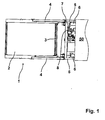
- FIG. 1 has the lifting device designated 1, the platform 2, wherein the platform 2, the bridge plate 3 designated pivotable receives.
- the two articulated arms 4 (FIG. FIG. 2 ff), which are arranged on the one hand on the platform 2, and on the other hand articulated to the carriage 5 generally designated.
- the carriage 5 also has the two piston cylinder drives 6, which engage a connecting the two articulated arms 4 traverse 7 and ensure that the platform deposed ( FIG. 2 ) or raised, as can be seen from the Figures 3 and 4 results.
- the drive 8 is provided for retraction of the carriage in the housing of the bus.
- the push rod 10 includes a fork arm 11 which is pivotally mounted on the platform 2 by an axis 11a.
- the fork arm 11 has at its one end via an intermediate member 11 b, the push rod 12.
- the push rod 12 is mounted on the platform in the direction of arrow 13 axially movable.
- the fork arm 11 a has at its upper end the fork 15, wherein in the fork 15 a pin 17 rotatably supports, which is fixed to the articulated arm 4.
- the pivot axis 20 for receiving the bridge plate 3 it follows that the pivot axis 20 at its one, in the installed state lower end a Aufstellnocken 21 and at its other upper end a stop cam 22 has.
- the Aufstellnocken 21 cooperates with the push rod 12; above the push rod 12 is the total designated 30 stop.
- the stop 30 comprises a stop rod 31 which is displaceable in the direction of the arrow 35 against the force of the spring 33.
- the stop rod 31 has an end stopper head 32 which cooperates with the stop cam 22.
- FIG. 2a the operation of the lifting device in relation to the push rod 10 is as follows:
- the platform labeled 2 is on the ground and allows the wheelchair user to access the platform.
- the piston-cylinder drive 6, which is articulated on the traverse 7, which connects the two articulated arms 4 the platform 3 via a position according to FIG. 3 in the position according to FIG. 4 transferred.
- the articulated arms 4 change their position relative to the platform 2.
- the fork 15 moves in the direction of arrow 18 about the axis 11 a.
- the platform is in a position according to FIG. 3 transferred.
- the carriage 5 then retracts the platform 2 in the direction of the arrow 53, wherein when the bridge plate 3 abuts against the end face 51 of the housing 50, the Bridge plate 3 is pivoted against the direction of the arrow 9.
- the stopper head 32 of the stopper rod 31 is displaced by the stop cam 22 of the pivot axis 20 in the direction of the arrow 35, wherein in this case the spring 33 is compressed, that is biased. That is, in the retracted state of the platform, the bridge plate 3 rests on the platform 2, wherein in this case the spring 33 of the stopper 30 is biased.
- the bridge plate is set up so far in order to prevent rising in the bus people ascend to the lowering platform.
Landscapes
- Health & Medical Sciences (AREA)
- Public Health (AREA)
- Life Sciences & Earth Sciences (AREA)
- Animal Behavior & Ethology (AREA)
- General Health & Medical Sciences (AREA)
- Veterinary Medicine (AREA)
- Vehicle Step Arrangements And Article Storage (AREA)
- Body Structure For Vehicles (AREA)
Description
- Die vorliegende Erfindung betrifft eine Rollstuhlhubvorrichtung zur Anbringung an einem Fahrzeug, z. B. einem Bus oder einem Schienenfahrzeug, umfassend eine Plattform mit daran schwenkbar angelenkter Brückenplatte, wobei die Plattform durch mindestens einen Schlitten gehalten ist, wobei der Schlitten in einem Gehäuse des Fahrzeugs ein- und ausfahrbar gelagert ist, wobei der Schlitten mit der Plattform durch zwei zu beiden Seiten der Plattform angeordnete Gelenkarme verbunden ist, wobei der Schlitten mindestens einen Antrieb zur Verbindung mit den Gelenkarmen aufweist, wobei die Brückenplatte durch eine Schwenkachse an der Plattform schwenkbar gelagert ist, wobei ein Schubgehäuse vorgesehen ist, das an einem Ende mit dem mindestens einen Gelenkarm zwangsgekoppelt ist, und das am anderen Ende mit der Schwenkachse der Brückenplatte die Schwenkachse drehend in Verbindung steht.
- Gegenstand dieser niederländischen Patentschrift
1021891 - Nun ist es so, dass der Zugang zu einem Bus oder auch zu einem Schienenfahrzeug über Stufen erfolgt. Das Anheben der Plattform erfolgt ausschließlich in vertikaler, also senkrechter Richtung mit der Folge, dass noch ein Raum zwischen dem Ende der Plattform und dem Boden, z. B. eines Busses, der durch die Stufen bedingt ist, überbrückt werden muss. Hierzu dient die sogenannte Brückenplatte.
- Wie bereits an anderer Stelle erwähnt, ist ein Antrieb vorgesehen, der den Schlitten, an dem die Brückenplatte angelenkt ist, ausfährt bzw. einzieht.
- Ein weiterer Antrieb ist erforderlich, um die Brückenplatte durch die Gelenkarme anzuheben bzw. abzusenken. Nach dem Stand der Technik gemäß der zuvor erwähnten niederländischen Patentschrift
1021891 - Die zuvor beschriebene Rollstuhlhubvorrichtung hat sich durchaus im täglichen Einsatz bewährt. Sie ist jedoch relativ teuer, was insbesondere auch daher rührt, dass mindestens fünf Antriebe vorgesehen sind, damit sowohl die Plattform als auch die Brückenplatte und auch der Schlitten die vorgesehenen Bewegungen ausführen können. So ist ein Antrieb vorgesehen zum Ausfahren des Schlittens, zwei parallel wirkende Kolbenzylinderantriebe zum Absenken und Anheben der Plattform sowie zwei Kolbenzylinderantriebe zum Verschwenken der Brückenplatte.
- Aus der
WO 94/27546 Fig. 2 der Entgegenhaltung ergibt. In der inFig. 2 dargestellten Stellung wird dann die Plattform eingezogen. Beim Absenken der Rampenplattform hingegen wird die Brückenplatte in eine senkrechte Stellung gebracht. Da die Höhe der Kassette im Fahrzeugboden, die die Rampenplattform aufnimmt, nur relativ gering ist, kann die Brückenplatte bei Schrägstellung auch nur eine relativ geringe Höhe aufweisen. Andernfalls würde die Plattform nicht eingezogen werden können. Dies ist insbesondere dann von Relevanz, wenn zum Überbrücken des Abstands von der hinteren Kante der Rampenplattform zum Boden des Fahrzeugs eine Brückenplatte größerer Länge erforderlich ist, wie dies beispielsweise dann der Fall ist, wenn nicht nur eine Treppenstufe überbrückt werden muss, sondern, wie dies häufig der Fall ist, der Abstand aufgrund zweier oder dreier Treppenstufen. Mit einer Konstruktion gemäß der Entgegenhaltung sind derartige Abstände dann nicht mehr zu überbrücken, bzw. eine solche Rampenplattform mit leicht abgeschwenkter Brückenplatte wäre dann nicht mehr in die Kassette des Fahrzeugs einfahrbar, weil die Brückenplatte wesentlich zu lang ist, und infolgedessen über die Kassette übersteht. - Darüber hinaus ist sicherzustellen, dass unmittelbar nach ausgefahrener Rampenplattform die im Bus befindlichen Personen daran gehindert werden, auf die Rampenplattform zu steigen. Auch ist sicherzustellen, dass der Rollstuhlfahrer beim Anheben der Rampe nicht vor Erreichen der Endstellung der Rampenplattform, in welcher der Rollstuhlfahrer in das Innere des Fahrzeugs gelangen kann, von der Rampenplattform abrollen kann. Das heiß, dass in dem Moment, wo die Rampenplattform aus der Kassette im Boden des Fahrzeugs ausgefahren ist, die Brückenplatte hoch stehen muss, um eben, wie bereits ausgeführt, zu verhindern, dass Personen aus dem Fahrzeug auf die ausgefahrene Rampenplattform aufsteigen können, und es muss darüber hinaus sichergestellt sein, dass dann, wenn sich ein Rollstuhlfahrer auf der Rampenplattform befindet, dieser gegen Herabrollen gesichert ist; dies geschieht durch das Aufstellen der Brückenplatte auf zumindest der einen Seite der Rampenplattform.
- Die der Erfindung zugrunde liegende Aufgabe besteht demzufolge darin, eine Rollstuhlhubvorrichtung der eingangs genannten Art bereitzustellen, mit der einerseits auch größere Abstände zwischen der hinteren Kante der Rampenplattform und dem Fahrzeugboden überbrückt werden können, wie dies beispielsweise der Fall ist, wenn der Aufgang des Fahrzeugs mehrere Treppenstufen umfasst, und dennoch die Rampenplattform samt Brückenplatte in das Gehäuse im Fahrzeugboden eingezogen werden können soll, und andererseits sichergestellt ist, dass unmittelbar nach Ausfahren der Rampenplattform aus der Kassette im Boden des Fahrzeugs die Brückenplatte aufgestellt ist, und erst abklappt, wenn die Rampenplattform für das Abfahren des Rollstuhlfahrers die erforderliche Endstellung erreicht hat.
- Die Aufgabe wird erfindungsgemäß wie beansprucht dadurch gelöst, dass ein auf die Schwenkachse wirkender Anschlag vorgesehen ist, der federbelastet ist, so dass bei ausgefahrener Rampenplattform durch den federbelasteten Anschlag die Brückenplatte aufgeschwenkt wird.
- Vorteilhafte Merkmale sind den Unteransprüchen zu entnehmen.
- In diesem Zusammenhang ist insbesondere vorgesehen, dass das Schubgestänge einen Gabelarm umfasst, wobei der Gabelarm endseitig eine Gabel aufweist, die formschlüssig aber gelenkig mit dem mindestens einen Gelenkarm in Verbindung steht. Durch die Gabel des Gabelarmes wird ein Stift erfasst, der an dem Gelenkarm angeordnet ist; der Stift wird drehbar durch die Gabel aufgenommen. Durch die Bewegung des Gelenkarmes beim Anheben bzw. Absetzen der Plattform wird der Gabelarm, der schwenkbar an der Plattform gelagert ist, in horizontaler Richtung, d. h. parallel zur Tiefe oder Länge der Plattform, bewegt. An den Gabelarm schließt sich eine Schubstange an, wobei diese Schubstange mit der Schwenkachse der Brückenplatte in Verbindung bzw. in Eingriff steht. In Eingriff steht die Schubstange mit der Schwenkachse der Brückenplatte beispielsweise insofern, als die Schwenkachse einen Nocken aufweist, der mit der Schubstange zusammenwirkt, ohne dass dort eine stoffliche Verbindung bestehen müsste. Geht man nunmehr vom ausgefahrenen Zustand der Plattform aus, d. h. die Plattform steht auf dem Boden auf, und geht man weiterhin davon aus, dass ausgehend von dieser unteren Stellung die Plattform angehoben wird, dann wird sich bei Anheben der Plattform durch die Gelenkarme der Winkel der Gelenkarme relativ zur Plattform nach Art eines Parallelogrammlenkers verändern. Dies bedingt eine Änderung der Stellung der Gabel des Gabelarmes relativ zum Gelenkarm, was gleichzeitig eine Verschiebung der Schubstange, die mit dem Gelenkarm in Verbindung steht, hervorruft. Das heißt, die Schubstange wird sich in Richtung der Schwenkachse der Brückenplatte oder von dieser weg bewegen.
- Wie bereits ausgeführt, besitzt die Schwenkachse einen Aufstellnocken, wobei der Aufstellnocken bei Anheben der Plattform am Ende der Schubstange anliegt, und wobei bei weiterem Anheben der Plattform die Brückenplatte in Abhängigkeit von der Stellung der Plattform sich nunmehr nach hinten umlegt und dem Rollstuhlfahrer den Zugang in das Innere des Fahrzeugs, z. B. des Busses, ermöglicht. In diesem Zusammenhang ist der sogenannte Anschlag vorgesehen, der auf die Schwenkachse der Brückenplatte wirkt. Dieser Anschlag ist - wie ausgeführt - federbelastet, wobei für den Anschlag an der Schwenkachse ein Anschlagnocken vorgesehen ist, wobei der Anschlag eine Anschlagstange umfasst, die bei Drehung der Schwenkachse durch den an der Schwenkachse angeordneten Anschlagnocken gegen die Kraft der Feder verschieblich ist.
- Das bedeutet, dass im eingefahrenen Zustand der Plattform, wobei in diesem Zustand die Brückenplatte auf der Plattform aufliegt, unmittelbar nach Ausfahren der Plattform mit Hilfe des bereits zuvor erwähnten Schlittens, die Brückenplatte sich aufgrund des federbelasteten Anschlags, der auf den Anschlagnocken wirkt, aufstellt und in eine Position im Wesentlichen senkrecht zur Plattform übergeht, in der sie dann verbleibt. Die Plattform kann in diesem Zustand nicht nach hinten abschwenken, da die Schubstange an dem Aufstellnocken der Schwenkachse der Brückenplatte anliegt, und insofern verhindert, dass die Brückenplatte im abgesetzten Zustand der Plattform weiter als etwa 90° Grad aufschwenkt. Hieraus wird deutlich, dass die Schubstange die Schwenkachse über den Aufstellnocken blockiert. Wird dann die Plattform angehoben, dann erfolgt ein Ausschwenken der Brückenplatte über 90° Grad hinaus bis maximal 180° Grad, die die Brückenplatte dann erreicht, wenn sich die Plattform in einer Ebene mit dem Fahrzeugboden befindet.
- Anhand der Zeichnungen wird die Erfindung nachstehend beispielhaft näher erläutert.
- Figur 1
- zeigt die Plattform in einer Ansicht von oben als schematische Darstellung;
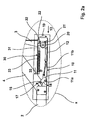
- Figur 2
- zeigt eine Seitenansicht, wobei sich die Plattform im abgesetzten Zustand befindet;
- Figur 2a
- zeigt die Einzelheit X aus
Fig. 2 in vergrößerter Darstellung; - Figur 3
- zeigt eine Stellung, bei der sich die Plattform in etwa auf der Ebene des Schlittens befindet;
- Figur 4
- zeigt eine Stellung, bei der sich die Plattform in der Höhe des Bodens des Fahrzeugs befindet.
- Gemäß
Figur 1 weist die mit 1 bezeichnete Hubvorrichtung die Plattform 2 auf, wobei die Plattform 2 die mit 3 bezeichnete Brückenplatte schwenkbar aufnimmt. Darüber hinaus erkennbar sind die beiden Gelenkarme 4 (Figur 2 ff), die einerseits an der Plattform 2 angeordnet sind, und andererseits gelenkig an dem insgesamt mit 5 bezeichneten Schlitten befestigt sind. Der Schlitten 5 besitzt darüber hinaus die beiden Kolbenzylinderantriebe 6, die an eine die beiden Gelenkarme 4 verbindende Traverse 7 angreifen und die dafür sorgen, dass die Plattform abgesetzt (Figur 2 ) oder angehoben werden kann, wie sich dies aus denFiguren 3 und4 ergibt. Zum Einziehen des Schlittens in das Gehäuse des Busses ist der Antrieb 8 vorgesehen. - Gegenstand der eigentlichen Erfindung ist nunmehr die Zwangssteuerung der Brückenplatte durch das Schubgestänge 10. Das Schubgestänge 10 umfasst einen Gabelarm 11, der an der Plattform 2 durch eine Achse 11a schwenkbeweglich gelagert ist. Der Gabelarm 11 weist an seinem einen Ende über ein Zwischenglied 11 b die Schubstange 12 auf. Die Schubstange 12 ist an der Plattform in Richtung des Pfeils 13 axial beweglich gelagert. Der Gabelarm 11 a weist an seinem oberen Ende die Gabel 15 auf, wobei in der Gabel 15 ein Stift 17 drehbar lagert, der an dem Gelenkarm 4 befestigt ist.
- Betrachtet man nunmehr die Schwenkachse 20 zur Aufnahme der Brückenplatte 3, so ergibt sich, dass die Schwenkachse 20 an ihrem einen, im Einbauzustand unteren Ende einen Aufstellnocken 21 und an ihrem anderen oberen Ende einen Anschlagnocken 22 aufweist. Der Aufstellnocken 21 arbeitet mit der Schubstange 12 zusammen; oberhalb der Schubstange 12 befindet sich der insgesamt mit 30 bezeichnete Anschlag. Der Anschlag 30 umfasst eine Anschlagstange 31, die in Richtung des Pfeils 35 gegen die Kraft der Feder 33 verschieblich ist. Die Anschlagstange 31 weist endseitig einen Anschlagkopf 32 auf, der mit dem Anschlagnocken 22 zusammenwirkt.
- Ausgehend der
Figur 2 bzw.Figur 2a stellt sich die Funktionsweise der Hubvorrichtung in Bezug das Schubgestänge 10 wie folgt dar: Im Zustand gemäßFigur 2 befindet sich die mit 2 bezeichnete Plattform beispielsweise auf dem Boden und ermöglicht dem Rollstuhlfahrer auf die Plattform aufzufahren. Nunmehr wird mit Hilfe des Kolbenzylinderantriebes 6, der an der Traverse 7 angelenkt ist, die die beiden Gelenkarme 4 verbindet, die Plattform 3 über eine Stellung gemäßFigur 3 in die Stellung gemäßFigur 4 überführt. Beim Anheben der Plattform 2 verändern die Gelenkarme 4 ihre Stellung relativ zur Plattform 2. Wie bereits ausgeführt besteht durch den Stift 17, der an dem Gelenkarm 4 angeordnet ist, und der Gabel 15 des Gabelarms 11 eine Verbindung mit der Schubstange 12. Bei Anheben der Plattform 2 bewegt sich die Gabel 15 in Richtung des Pfeils 18 um die Achse 11 a. Hierbei wird die Schubstange aus der Stellung gemäßFigur 2 in Richtung der Plattform 2 gezogen. In der Stellung gemäßFigur 2 ist die Schwenkachse 20 blockiert, und zwar insofern, als die Schwenkachse 20 mit ihrem Aufstellnocken 21 auf der Schubstange 12 aufsitzt, wie dies unmittelbar in Anschauung vonFigur 2a erkennbar ist. Wird nun - wie bereits ausgeführt - die Schubstange 12 in Richtung der Plattform gezogen, dann verdreht sich die Schwenkachse 20 mit dem Aufstellnocken 21 an der Stirnseite der Schubstange 12 anliegend in Richtung des Pfeils 19. Dies ermöglicht der Brückenplatte eine Verschwenkung in Richtung des Pfeils 9, wobei in der Endstellung die Brückenplatte eine Stellung gemäßFigur 4 einnimmt und dem Rollstuhlfahrer es ermöglicht, von der Plattform 2 in das Innere des Busses zu gelangen. - Wird die Hubvorrichtung nun nicht mehr benötigt, so muss sie in das Gehäuse 50 im Wagenkasten des Busses eingezogen werden. Hierzu wird die Plattform in eine Stellung gemäß
Figur 3 überführt. Der Schlitten 5 zieht dann die Plattform 2 in Richtung des Pfeils 53 ein, wobei dann, wenn die Brückenplatte 3 an die Stirnseite 51 des Gehäuses 50 anschlägt, die Brückenplatte 3 entgegen der Richtung des Pfeils 9 verschwenkt wird. Hierbei wird der Anschlagkopf 32 der Anschlagstange 31 durch den Anschlagnocken 22 der Schwenkachse 20 in Richtung des Pfeils 35 verschoben, wobei hierbei die Feder 33 zusammengedrückt, also vorgespannt wird. Das heißt, im eingezogenen Zustand der Plattform liegt die Brückenplatte 3 auf der Plattform 2 auf, wobei hierbei die Feder 33 des Anschlags 30 vorgespannt ist. Unmittelbar nach Ausfahren der Plattform wird sich insofern die Brückenplatte unmittelbar aufstellen, um zu verhindern, dass im Bus anstehende Personen auf die sich absenkende Plattform aufsteigen.
Claims (5)
- Rollstuhlhubvorrichtung (1) zur Anbringung an einem Fahrzeug, z. B. einem Bus oder einem Schienenfahrzeug, umfassend eine Plattform (2) mit daran schwenkbar angelenkter Brückenplatte (3), wobei die Plattform (2) durch mindestens einen Schlitten (5) gehalten ist, wobei der Schlitten (5) in einem Gehäuse (50) des Fahrzeugs ein- und ausfahrbar gelagert ist, wobei der Schlitten (5) mit der Plattform (2) durch zwei zu beiden Seiten der Plattform (2) angeordnete Gelenkarme (4) verbunden ist, wobei der Schlitten (5) mindestens einen Antrieb (6) zur Verbindung mit den Gelenkarmen (4) aufweist, wobei die Brückenplatte (3) durch eine Schwenkachse (20) in der Plattform (2) schwenkbar gelagert ist, wobei ein Schubgestänge (10) vorgesehen ist, das an einem Ende mit dem mindestens einen Gelenkarm (4) zwangsgekoppelt ist, und das am anderen Ende mit der Schwenkachse (20) der Brückenplatte (3) die Schwenkachse (20) drehend in Verbindung steht,
dadurch gekennzeichnet,
dass ein auf die Schwenkachse (20) wirkender Anschlag (30) vorgesehen ist, der federbelastet ist, so dass bei ausgefahrener Rampenplattform (2) durch den federbelasteten Anschlag die Brückenplatte (3) (3) aufgeschwenkt wird. - Rollstuhlhubvorrichtung nach Anspruch 1,
dadurch gekennzeichnet,
dass das Schubgestänge (10) einen Gabelarm (11) umfasst, wobei der Gabelarm (11) endseitig eine Gabel (15) aufweist, die formschlüssig und verdrehbar mit dem mindestens einen Gelenkarm (4) in Verbindung steht. - Rollstuhlhubvorrichtung nach Anspruch 2,
dadurch gekennzeichnet,
dass der Gabelarm (11) schwenkbar an der Plattform (2) gelagert ist. - Rollstuhlhubvorrichtung nach einem der Ansprüche 2 oder 3,
dadurch gekennzeichnet, dass der Gabelarm (11) eine Schubstange (12) aufweist, und dass die
Schwenkachse (20) zur Aufnahme der Brückenplatte (3) einen Aufstellnocken (21) besitzt, der in Verbindung mit der Schubstange (12) steht. - Rollstuhlhubvorrichtung nach Anspruch 1,
dadurch gekennzeichnet,
dass der Anschlag (30) eine Anschlagstange (31) umfasst, die bei Drehung der Schwenkachse (20) durch den an der Schwenkachse (20) angeordneten Anschlagnocken (22) gegen die Kraft einer Feder (33) verschieblich ist.
Priority Applications (1)
| Application Number | Priority Date | Filing Date | Title |
|---|---|---|---|
| PL08011969T PL2070498T3 (pl) | 2007-12-12 | 2008-07-03 | Podnośnik do wózka inwalidzkiego |
Applications Claiming Priority (1)
| Application Number | Priority Date | Filing Date | Title |
|---|---|---|---|
| DE102007059943A DE102007059943B4 (de) | 2007-12-12 | 2007-12-12 | Rollstuhlhubvorrichtung |
Publications (3)
| Publication Number | Publication Date |
|---|---|
| EP2070498A2 EP2070498A2 (de) | 2009-06-17 |
| EP2070498A3 EP2070498A3 (de) | 2011-05-04 |
| EP2070498B1 true EP2070498B1 (de) | 2012-08-29 |
Family
ID=40377604
Family Applications (2)
| Application Number | Title | Priority Date | Filing Date |
|---|---|---|---|
| EP08011969A Active EP2070498B1 (de) | 2007-12-12 | 2008-07-03 | Rollstuhlhubvorrichtung |
| EP08013384A Active EP2070499B1 (de) | 2007-12-12 | 2008-07-25 | Rollstuhlhubvorrichtung |
Family Applications After (1)
| Application Number | Title | Priority Date | Filing Date |
|---|---|---|---|
| EP08013384A Active EP2070499B1 (de) | 2007-12-12 | 2008-07-25 | Rollstuhlhubvorrichtung |
Country Status (4)
| Country | Link |
|---|---|
| US (2) | US7810198B2 (de) |
| EP (2) | EP2070498B1 (de) |
| DE (1) | DE102007059943B4 (de) |
| PL (2) | PL2070498T3 (de) |
Families Citing this family (13)
| Publication number | Priority date | Publication date | Assignee | Title |
|---|---|---|---|---|
| DE60315846T2 (de) | 2002-10-04 | 2008-05-21 | Tyco Healthcare Group Lp, Norwalk | Zusammenbau von chirurgischem klammerwerkzeug |
| US7726446B1 (en) * | 2005-01-28 | 2010-06-01 | Vernon Roger Buchanan | Mobile hunting blind |
| US9327632B1 (en) | 2009-01-30 | 2016-05-03 | Excel Industries, Inc. | Translating cargo bed |
| GB2493502A (en) * | 2011-07-22 | 2013-02-13 | Passenger Lift Services Ltd | Lift apparatus for a vehicle |
| BR112015013469A2 (pt) * | 2012-12-11 | 2017-07-11 | Honda Motor Co Ltd | dispositivo de montagem para objeto a ser montado |
| FR3020081B1 (fr) * | 2014-04-22 | 2016-05-06 | Myd L | Dispositif d'assistance au frachissement d'un obstacle par un vehicule |
| US9546458B1 (en) * | 2015-06-12 | 2017-01-17 | Sam Carbis Asset Management, Llc | Device for resisting lifting of a gangway and gangway fitted with such device |
| DE102015008096B4 (de) * | 2015-06-25 | 2018-12-27 | Walter Runkel | "Lift, insbesondere für die Beförderung von Rollstuhlfahrern" |
| EP3156025A1 (de) * | 2015-10-14 | 2017-04-19 | Palfinger Tail Lifts GmbH | Hubbühne |
| CN105522972B (zh) * | 2015-12-09 | 2017-11-21 | 马清海 | 一种用于上下公交车的辅助装置 |
| JP7559725B2 (ja) * | 2021-09-21 | 2024-10-02 | トヨタ自動車株式会社 | 車両 |
| CN115611123B (zh) * | 2022-08-30 | 2026-01-23 | 安徽春江重工科技有限公司 | 一种智能自动平层的物料提升机 |
| CN115738141B (zh) * | 2022-11-16 | 2023-08-22 | 北京泰和佳科技股份有限公司 | 一种气溶胶灭火装置 |
Family Cites Families (16)
| Publication number | Priority date | Publication date | Assignee | Title |
|---|---|---|---|---|
| US4219104A (en) * | 1978-10-03 | 1980-08-26 | General Motors Corporation | Wheelchair lift device |
| US5040936A (en) * | 1990-02-21 | 1991-08-20 | Mobile-Tech Corporation | Barrier for lift platform |
| US5445488A (en) * | 1992-07-28 | 1995-08-29 | Ricon Corporation | Locking wheelchair lift |
| CA2159707A1 (en) * | 1993-05-26 | 1994-12-08 | Percy Fretwell | Vehicle lifts |
| US6039528A (en) * | 1996-12-31 | 2000-03-21 | Lift-U, Division Of Hogan Manufacturing, Inc. | Wheelchair lift with improved outer, inner, and side barriers |
| US5975830A (en) * | 1997-06-11 | 1999-11-02 | Goodrich; Ronald W. | Under floor wheelchair lift |
| US6102648A (en) * | 1997-09-05 | 2000-08-15 | Ricon Corporation | Driving mechanism for vehicle lifts |
| US6042327A (en) * | 1998-05-13 | 2000-03-28 | Ricon Corporation | Arm lever adaptor for adapting a handrail of a wheelchair lift |
| DK1079787T3 (da) * | 1998-05-29 | 2007-12-03 | Ricon Corp | Körestolslift med sammenklappelig platform |
| US6077025A (en) * | 1998-08-13 | 2000-06-20 | The Braun Corporation | Pivoting safety barrier for wheelchair lift |
| US6692217B1 (en) * | 1999-04-29 | 2004-02-17 | The Braun Corporation | Liftable platform having isolated hydraulically-moveable rollstop |
| US6179545B1 (en) * | 1999-11-04 | 2001-01-30 | Ricon Corporation | Flip-over ramp |
| NL1021891C2 (nl) * | 2002-11-11 | 2004-05-12 | Flevo Transportmiddelen Zeewol | Rolstoellift, alsmede voertuig voorzien van een dergelijke lift. |
| US7326024B2 (en) * | 2003-02-19 | 2008-02-05 | Lift-U, Division Of Hogan Mfg., Inc. | Wheelchair lift assembly having a compact stowed profile |
| ITUD20050134A1 (it) * | 2005-08-22 | 2007-02-23 | Mobility Trend S R L | Pedana perfezionata di sollevamento per persone e/o merci, adatta per mezzi di trasporto in genere |
| US7441995B2 (en) * | 2005-09-27 | 2008-10-28 | The Braun Corporation | Cam-actuated locking inboard barrier |
-
2007
- 2007-12-12 DE DE102007059943A patent/DE102007059943B4/de not_active Expired - Fee Related
-
2008
- 2008-07-03 PL PL08011969T patent/PL2070498T3/pl unknown
- 2008-07-03 EP EP08011969A patent/EP2070498B1/de active Active
- 2008-07-25 EP EP08013384A patent/EP2070499B1/de active Active
- 2008-07-25 PL PL08013384T patent/PL2070499T3/pl unknown
- 2008-09-03 US US12/231,460 patent/US7810198B2/en not_active Expired - Fee Related
- 2008-09-17 US US12/284,000 patent/US20090155037A1/en not_active Abandoned
Also Published As
| Publication number | Publication date |
|---|---|
| PL2070499T3 (pl) | 2013-01-31 |
| US20090151094A1 (en) | 2009-06-18 |
| DE102007059943A1 (de) | 2009-06-25 |
| EP2070498A2 (de) | 2009-06-17 |
| EP2070499B1 (de) | 2012-08-29 |
| EP2070499A2 (de) | 2009-06-17 |
| EP2070498A3 (de) | 2011-05-04 |
| EP2070499A3 (de) | 2011-08-10 |
| US7810198B2 (en) | 2010-10-12 |
| PL2070498T3 (pl) | 2013-01-31 |
| US20090155037A1 (en) | 2009-06-18 |
| DE102007059943B4 (de) | 2010-02-04 |
Similar Documents
| Publication | Publication Date | Title |
|---|---|---|
| EP2070498B1 (de) | Rollstuhlhubvorrichtung | |
| DE60207380T2 (de) | Leiterhalter für hochbaulieferwagen | |
| DE60127771T2 (de) | Brückenuntersichtvorrichtung mit Querverbindung zwischen Turm und Fahrzeugrahmen | |
| EP3549900A1 (de) | Hebebühne für kraftfahrzeuge | |
| DE2620683A1 (de) | Einstieganordnung fuer ein nahverkehrsfahrzeug | |
| WO1986006707A1 (fr) | Cric | |
| DE102005024585B4 (de) | Drehleiter für Rettungsfahrzeuge | |
| DE3228829A1 (de) | Ladevorrichtung fuer lastfahrzeugaufbauten | |
| EP1323871B1 (de) | "Abstützvorrichtung für Baumaschinen wie Hydraulikbagger und dergleichen" | |
| WO2017140917A1 (de) | Höhenzugang-auslegereinheit für eine mobile höhenzugangsmaschine, eine höhenzugangsmaschine und eine verwendung der höhenzugang-auslegereinheit | |
| DE102006042498A1 (de) | Fußgänger-Schutz-Vorrichtung an einem Kraftfahrzeug | |
| DE20206720U1 (de) | Hebebühne für Kraftfahrzeuge | |
| DE3033400C2 (de) | ||
| EP1882654B1 (de) | Überladebrücke mit Sicherheitssperre und Verfahren zum Betreiben der Überladebrücke | |
| DE3526041C2 (de) | Hochschwenkbare Abstützung für Arbeitsmaschinen, insbesondere für Kräne, Bagger od.dgl. | |
| DE19748637C1 (de) | Flüssigkeitscontainer | |
| EP0831054A2 (de) | Hubvorrichtung, insbesondere Scherenbühne | |
| EP2318301B1 (de) | Hebebühne | |
| DE202008017391U1 (de) | Abstützvorrichtung für ein Auslegerfahrzeug | |
| DE4135653C2 (de) | Abstützvorrichtung für Sonderfahrzeuge, insbesondere für fahrbare Betonpumpe | |
| DE102010036690A1 (de) | Fahrzeug und Abstützvorrichtung | |
| DE202005006245U1 (de) | Sitz- und/oder Liegemöbel | |
| DE1267397B (de) | Abstuetzvorrichtung fuer Fahrzeuge, insbesondere Strassenfahrzeuge mit aufmontiertemKran | |
| DE1755332C3 (de) | Lade- und Entladevorrichtung für sperrige Lasten | |
| DE2846554A1 (de) | Fahrzeug zum transport von fertiggaragen o.dgl. |
Legal Events
| Date | Code | Title | Description |
|---|---|---|---|
| PUAI | Public reference made under article 153(3) epc to a published international application that has entered the european phase |
Free format text: ORIGINAL CODE: 0009012 |
|
| AK | Designated contracting states |
Kind code of ref document: A2 Designated state(s): AT BE BG CH CY CZ DE DK EE ES FI FR GB GR HR HU IE IS IT LI LT LU LV MC MT NL NO PL PT RO SE SI SK TR |
|
| AX | Request for extension of the european patent |
Extension state: AL BA MK RS |
|
| PUAL | Search report despatched |
Free format text: ORIGINAL CODE: 0009013 |
|
| AK | Designated contracting states |
Kind code of ref document: A3 Designated state(s): AT BE BG CH CY CZ DE DK EE ES FI FR GB GR HR HU IE IS IT LI LT LU LV MC MT NL NO PL PT RO SE SI SK TR |
|
| AX | Request for extension of the european patent |
Extension state: AL BA MK RS |
|
| 17P | Request for examination filed |
Effective date: 20110524 |
|
| AKX | Designation fees paid |
Designated state(s): AT BE BG CH CY CZ DE DK EE ES FI FR GB GR HR HU IE IS IT LI LT LU LV MC MT NL NO PL PT RO SE SI SK TR |
|
| GRAP | Despatch of communication of intention to grant a patent |
Free format text: ORIGINAL CODE: EPIDOSNIGR1 |
|
| GRAS | Grant fee paid |
Free format text: ORIGINAL CODE: EPIDOSNIGR3 |
|
| GRAA | (expected) grant |
Free format text: ORIGINAL CODE: 0009210 |
|
| AK | Designated contracting states |
Kind code of ref document: B1 Designated state(s): AT BE BG CH CY CZ DE DK EE ES FI FR GB GR HR HU IE IS IT LI LT LU LV MC MT NL NO PL PT RO SE SI SK TR |
|
| REG | Reference to a national code |
Ref country code: GB Ref legal event code: FG4D Free format text: NOT ENGLISH |
|
| REG | Reference to a national code |
Ref country code: CH Ref legal event code: EP |
|
| REG | Reference to a national code |
Ref country code: AT Ref legal event code: REF Ref document number: 572629 Country of ref document: AT Kind code of ref document: T Effective date: 20120915 |
|
| REG | Reference to a national code |
Ref country code: NL Ref legal event code: T3 |
|
| REG | Reference to a national code |
Ref country code: IE Ref legal event code: FG4D Free format text: LANGUAGE OF EP DOCUMENT: GERMAN |
|
| REG | Reference to a national code |
Ref country code: DE Ref legal event code: R096 Ref document number: 502008008043 Country of ref document: DE Effective date: 20121025 |
|
| REG | Reference to a national code |
Ref country code: SE Ref legal event code: TRGR |
|
| REG | Reference to a national code |
Ref country code: LT Ref legal event code: MG4D Effective date: 20120829 |
|
| PG25 | Lapsed in a contracting state [announced via postgrant information from national office to epo] |
Ref country code: NO Free format text: LAPSE BECAUSE OF FAILURE TO SUBMIT A TRANSLATION OF THE DESCRIPTION OR TO PAY THE FEE WITHIN THE PRESCRIBED TIME-LIMIT Effective date: 20121129 Ref country code: CY Free format text: LAPSE BECAUSE OF FAILURE TO SUBMIT A TRANSLATION OF THE DESCRIPTION OR TO PAY THE FEE WITHIN THE PRESCRIBED TIME-LIMIT Effective date: 20120829 Ref country code: FI Free format text: LAPSE BECAUSE OF FAILURE TO SUBMIT A TRANSLATION OF THE DESCRIPTION OR TO PAY THE FEE WITHIN THE PRESCRIBED TIME-LIMIT Effective date: 20120829 Ref country code: IS Free format text: LAPSE BECAUSE OF FAILURE TO SUBMIT A TRANSLATION OF THE DESCRIPTION OR TO PAY THE FEE WITHIN THE PRESCRIBED TIME-LIMIT Effective date: 20121229 Ref country code: LT Free format text: LAPSE BECAUSE OF FAILURE TO SUBMIT A TRANSLATION OF THE DESCRIPTION OR TO PAY THE FEE WITHIN THE PRESCRIBED TIME-LIMIT Effective date: 20120829 Ref country code: HR Free format text: LAPSE BECAUSE OF FAILURE TO SUBMIT A TRANSLATION OF THE DESCRIPTION OR TO PAY THE FEE WITHIN THE PRESCRIBED TIME-LIMIT Effective date: 20120829 |
|
| REG | Reference to a national code |
Ref country code: PL Ref legal event code: T3 |
|
| PG25 | Lapsed in a contracting state [announced via postgrant information from national office to epo] |
Ref country code: SI Free format text: LAPSE BECAUSE OF FAILURE TO SUBMIT A TRANSLATION OF THE DESCRIPTION OR TO PAY THE FEE WITHIN THE PRESCRIBED TIME-LIMIT Effective date: 20120829 Ref country code: GR Free format text: LAPSE BECAUSE OF FAILURE TO SUBMIT A TRANSLATION OF THE DESCRIPTION OR TO PAY THE FEE WITHIN THE PRESCRIBED TIME-LIMIT Effective date: 20121130 Ref country code: LV Free format text: LAPSE BECAUSE OF FAILURE TO SUBMIT A TRANSLATION OF THE DESCRIPTION OR TO PAY THE FEE WITHIN THE PRESCRIBED TIME-LIMIT Effective date: 20120829 Ref country code: PT Free format text: LAPSE BECAUSE OF FAILURE TO SUBMIT A TRANSLATION OF THE DESCRIPTION OR TO PAY THE FEE WITHIN THE PRESCRIBED TIME-LIMIT Effective date: 20121231 |
|
| PG25 | Lapsed in a contracting state [announced via postgrant information from national office to epo] |
Ref country code: EE Free format text: LAPSE BECAUSE OF FAILURE TO SUBMIT A TRANSLATION OF THE DESCRIPTION OR TO PAY THE FEE WITHIN THE PRESCRIBED TIME-LIMIT Effective date: 20120829 Ref country code: DK Free format text: LAPSE BECAUSE OF FAILURE TO SUBMIT A TRANSLATION OF THE DESCRIPTION OR TO PAY THE FEE WITHIN THE PRESCRIBED TIME-LIMIT Effective date: 20120829 Ref country code: RO Free format text: LAPSE BECAUSE OF FAILURE TO SUBMIT A TRANSLATION OF THE DESCRIPTION OR TO PAY THE FEE WITHIN THE PRESCRIBED TIME-LIMIT Effective date: 20120829 Ref country code: ES Free format text: LAPSE BECAUSE OF FAILURE TO SUBMIT A TRANSLATION OF THE DESCRIPTION OR TO PAY THE FEE WITHIN THE PRESCRIBED TIME-LIMIT Effective date: 20121210 |
|
| PG25 | Lapsed in a contracting state [announced via postgrant information from national office to epo] |
Ref country code: SK Free format text: LAPSE BECAUSE OF FAILURE TO SUBMIT A TRANSLATION OF THE DESCRIPTION OR TO PAY THE FEE WITHIN THE PRESCRIBED TIME-LIMIT Effective date: 20120829 |
|
| PLBE | No opposition filed within time limit |
Free format text: ORIGINAL CODE: 0009261 |
|
| STAA | Information on the status of an ep patent application or granted ep patent |
Free format text: STATUS: NO OPPOSITION FILED WITHIN TIME LIMIT |
|
| PG25 | Lapsed in a contracting state [announced via postgrant information from national office to epo] |
Ref country code: BG Free format text: LAPSE BECAUSE OF FAILURE TO SUBMIT A TRANSLATION OF THE DESCRIPTION OR TO PAY THE FEE WITHIN THE PRESCRIBED TIME-LIMIT Effective date: 20121129 |
|
| 26N | No opposition filed |
Effective date: 20130530 |
|
| REG | Reference to a national code |
Ref country code: DE Ref legal event code: R097 Ref document number: 502008008043 Country of ref document: DE Effective date: 20130530 |
|
| BERE | Be: lapsed |
Owner name: HUBNER TRANSPORTATION GBMH Effective date: 20130731 |
|
| PG25 | Lapsed in a contracting state [announced via postgrant information from national office to epo] |
Ref country code: MC Free format text: LAPSE BECAUSE OF FAILURE TO SUBMIT A TRANSLATION OF THE DESCRIPTION OR TO PAY THE FEE WITHIN THE PRESCRIBED TIME-LIMIT Effective date: 20120829 |
|
| REG | Reference to a national code |
Ref country code: IE Ref legal event code: MM4A |
|
| PG25 | Lapsed in a contracting state [announced via postgrant information from national office to epo] |
Ref country code: BE Free format text: LAPSE BECAUSE OF NON-PAYMENT OF DUE FEES Effective date: 20130731 |
|
| PG25 | Lapsed in a contracting state [announced via postgrant information from national office to epo] |
Ref country code: IE Free format text: LAPSE BECAUSE OF NON-PAYMENT OF DUE FEES Effective date: 20130703 |
|
| REG | Reference to a national code |
Ref country code: AT Ref legal event code: MM01 Ref document number: 572629 Country of ref document: AT Kind code of ref document: T Effective date: 20130703 |
|
| PGFP | Annual fee paid to national office [announced via postgrant information from national office to epo] |
Ref country code: PL Payment date: 20140624 Year of fee payment: 7 |
|
| PGFP | Annual fee paid to national office [announced via postgrant information from national office to epo] |
Ref country code: CH Payment date: 20140721 Year of fee payment: 7 Ref country code: NL Payment date: 20140721 Year of fee payment: 7 |
|
| PG25 | Lapsed in a contracting state [announced via postgrant information from national office to epo] |
Ref country code: AT Free format text: LAPSE BECAUSE OF NON-PAYMENT OF DUE FEES Effective date: 20130703 |
|
| PGFP | Annual fee paid to national office [announced via postgrant information from national office to epo] |
Ref country code: SE Payment date: 20140721 Year of fee payment: 7 |
|
| PGFP | Annual fee paid to national office [announced via postgrant information from national office to epo] |
Ref country code: IT Payment date: 20140725 Year of fee payment: 7 |
|
| PG25 | Lapsed in a contracting state [announced via postgrant information from national office to epo] |
Ref country code: MT Free format text: LAPSE BECAUSE OF FAILURE TO SUBMIT A TRANSLATION OF THE DESCRIPTION OR TO PAY THE FEE WITHIN THE PRESCRIBED TIME-LIMIT Effective date: 20120829 |
|
| PG25 | Lapsed in a contracting state [announced via postgrant information from national office to epo] |
Ref country code: HU Free format text: LAPSE BECAUSE OF FAILURE TO SUBMIT A TRANSLATION OF THE DESCRIPTION OR TO PAY THE FEE WITHIN THE PRESCRIBED TIME-LIMIT; INVALID AB INITIO Effective date: 20080703 Ref country code: LU Free format text: LAPSE BECAUSE OF NON-PAYMENT OF DUE FEES Effective date: 20130703 |
|
| REG | Reference to a national code |
Ref country code: CH Ref legal event code: PL |
|
| REG | Reference to a national code |
Ref country code: SE Ref legal event code: EUG |
|
| REG | Reference to a national code |
Ref country code: NL Ref legal event code: MM Effective date: 20150801 |
|
| PG25 | Lapsed in a contracting state [announced via postgrant information from national office to epo] |
Ref country code: LI Free format text: LAPSE BECAUSE OF NON-PAYMENT OF DUE FEES Effective date: 20150731 Ref country code: CH Free format text: LAPSE BECAUSE OF NON-PAYMENT OF DUE FEES Effective date: 20150731 Ref country code: IT Free format text: LAPSE BECAUSE OF NON-PAYMENT OF DUE FEES Effective date: 20150703 |
|
| PG25 | Lapsed in a contracting state [announced via postgrant information from national office to epo] |
Ref country code: SE Free format text: LAPSE BECAUSE OF NON-PAYMENT OF DUE FEES Effective date: 20150704 Ref country code: NL Free format text: LAPSE BECAUSE OF NON-PAYMENT OF DUE FEES Effective date: 20150801 |
|
| REG | Reference to a national code |
Ref country code: FR Ref legal event code: PLFP Year of fee payment: 9 |
|
| PG25 | Lapsed in a contracting state [announced via postgrant information from national office to epo] |
Ref country code: PL Free format text: LAPSE BECAUSE OF NON-PAYMENT OF DUE FEES Effective date: 20150703 |
|
| PGFP | Annual fee paid to national office [announced via postgrant information from national office to epo] |
Ref country code: GB Payment date: 20160721 Year of fee payment: 9 |
|
| PGFP | Annual fee paid to national office [announced via postgrant information from national office to epo] |
Ref country code: FR Payment date: 20160721 Year of fee payment: 9 Ref country code: CZ Payment date: 20160630 Year of fee payment: 9 |
|
| PG25 | Lapsed in a contracting state [announced via postgrant information from national office to epo] |
Ref country code: CZ Free format text: LAPSE BECAUSE OF NON-PAYMENT OF DUE FEES Effective date: 20170703 |
|
| GBPC | Gb: european patent ceased through non-payment of renewal fee |
Effective date: 20170703 |
|
| REG | Reference to a national code |
Ref country code: FR Ref legal event code: ST Effective date: 20180330 |
|
| PG25 | Lapsed in a contracting state [announced via postgrant information from national office to epo] |
Ref country code: GB Free format text: LAPSE BECAUSE OF NON-PAYMENT OF DUE FEES Effective date: 20170703 |
|
| PG25 | Lapsed in a contracting state [announced via postgrant information from national office to epo] |
Ref country code: FR Free format text: LAPSE BECAUSE OF NON-PAYMENT OF DUE FEES Effective date: 20170731 |
|
| PGFP | Annual fee paid to national office [announced via postgrant information from national office to epo] |
Ref country code: TR Payment date: 20250627 Year of fee payment: 18 |
|
| PGFP | Annual fee paid to national office [announced via postgrant information from national office to epo] |
Ref country code: DE Payment date: 20250722 Year of fee payment: 18 |
|
| REG | Reference to a national code |
Ref country code: DE Ref legal event code: R081 Ref document number: 502008008043 Country of ref document: DE Owner name: HUEBNER GMBH & CO. KG, DE Free format text: FORMER OWNER: HUEBNER TRANSPORTATION GBMH, 34123 KASSEL, DE Ref country code: DE Ref legal event code: R082 Ref document number: 502008008043 Country of ref document: DE |