EP2070580A2 - Dispositif de purification de gaz d'échappement - Google Patents
Dispositif de purification de gaz d'échappement Download PDFInfo
- Publication number
- EP2070580A2 EP2070580A2 EP08171176A EP08171176A EP2070580A2 EP 2070580 A2 EP2070580 A2 EP 2070580A2 EP 08171176 A EP08171176 A EP 08171176A EP 08171176 A EP08171176 A EP 08171176A EP 2070580 A2 EP2070580 A2 EP 2070580A2
- Authority
- EP
- European Patent Office
- Prior art keywords
- exhaust gas
- downstream
- catalytic layer
- upstream
- reforming catalyst
- Prior art date
- Legal status (The legal status is an assumption and is not a legal conclusion. Google has not performed a legal analysis and makes no representation as to the accuracy of the status listed.)
- Withdrawn
Links
Images


Classifications
-
- B—PERFORMING OPERATIONS; TRANSPORTING
- B01—PHYSICAL OR CHEMICAL PROCESSES OR APPARATUS IN GENERAL
- B01D—SEPARATION
- B01D53/00—Separation of gases or vapours; Recovering vapours of volatile solvents from gases; Chemical or biological purification of waste gases, e.g. engine exhaust gases, smoke, fumes, flue gases, aerosols
- B01D53/34—Chemical or biological purification of waste gases
- B01D53/92—Chemical or biological purification of waste gases of engine exhaust gases
- B01D53/94—Chemical or biological purification of waste gases of engine exhaust gases by catalytic processes
- B01D53/9459—Removing one or more of nitrogen oxides, carbon monoxide, or hydrocarbons by multiple successive catalytic functions; systems with more than one different function, e.g. zone coated catalysts
- B01D53/9463—Removing one or more of nitrogen oxides, carbon monoxide, or hydrocarbons by multiple successive catalytic functions; systems with more than one different function, e.g. zone coated catalysts with catalysts positioned on one brick
- B01D53/9472—Removing one or more of nitrogen oxides, carbon monoxide, or hydrocarbons by multiple successive catalytic functions; systems with more than one different function, e.g. zone coated catalysts with catalysts positioned on one brick in different zones
-
- B—PERFORMING OPERATIONS; TRANSPORTING
- B01—PHYSICAL OR CHEMICAL PROCESSES OR APPARATUS IN GENERAL
- B01D—SEPARATION
- B01D53/00—Separation of gases or vapours; Recovering vapours of volatile solvents from gases; Chemical or biological purification of waste gases, e.g. engine exhaust gases, smoke, fumes, flue gases, aerosols
- B01D53/34—Chemical or biological purification of waste gases
- B01D53/74—General processes for purification of waste gases; Apparatus or devices specially adapted therefor
- B01D53/86—Catalytic processes
- B01D53/90—Injecting reactants
-
- B—PERFORMING OPERATIONS; TRANSPORTING
- B01—PHYSICAL OR CHEMICAL PROCESSES OR APPARATUS IN GENERAL
- B01D—SEPARATION
- B01D53/00—Separation of gases or vapours; Recovering vapours of volatile solvents from gases; Chemical or biological purification of waste gases, e.g. engine exhaust gases, smoke, fumes, flue gases, aerosols
- B01D53/34—Chemical or biological purification of waste gases
- B01D53/92—Chemical or biological purification of waste gases of engine exhaust gases
- B01D53/94—Chemical or biological purification of waste gases of engine exhaust gases by catalytic processes
- B01D53/9459—Removing one or more of nitrogen oxides, carbon monoxide, or hydrocarbons by multiple successive catalytic functions; systems with more than one different function, e.g. zone coated catalysts
- B01D53/9463—Removing one or more of nitrogen oxides, carbon monoxide, or hydrocarbons by multiple successive catalytic functions; systems with more than one different function, e.g. zone coated catalysts with catalysts positioned on one brick
- B01D53/9468—Removing one or more of nitrogen oxides, carbon monoxide, or hydrocarbons by multiple successive catalytic functions; systems with more than one different function, e.g. zone coated catalysts with catalysts positioned on one brick in different layers
-
- F—MECHANICAL ENGINEERING; LIGHTING; HEATING; WEAPONS; BLASTING
- F01—MACHINES OR ENGINES IN GENERAL; ENGINE PLANTS IN GENERAL; STEAM ENGINES
- F01N—GAS-FLOW SILENCERS OR EXHAUST APPARATUS FOR MACHINES OR ENGINES IN GENERAL; GAS-FLOW SILENCERS OR EXHAUST APPARATUS FOR INTERNAL-COMBUSTION ENGINES
- F01N13/00—Exhaust or silencing apparatus characterised by constructional features
- F01N13/009—Exhaust or silencing apparatus characterised by constructional features having two or more separate purifying devices arranged in series
-
- F—MECHANICAL ENGINEERING; LIGHTING; HEATING; WEAPONS; BLASTING
- F01—MACHINES OR ENGINES IN GENERAL; ENGINE PLANTS IN GENERAL; STEAM ENGINES
- F01N—GAS-FLOW SILENCERS OR EXHAUST APPARATUS FOR MACHINES OR ENGINES IN GENERAL; GAS-FLOW SILENCERS OR EXHAUST APPARATUS FOR INTERNAL-COMBUSTION ENGINES
- F01N3/00—Exhaust or silencing apparatus having means for purifying, rendering innocuous, or otherwise treating exhaust
- F01N3/08—Exhaust or silencing apparatus having means for purifying, rendering innocuous, or otherwise treating exhaust for rendering innocuous
- F01N3/0807—Exhaust or silencing apparatus having means for purifying, rendering innocuous, or otherwise treating exhaust for rendering innocuous by using absorbents or adsorbents
- F01N3/0814—Exhaust or silencing apparatus having means for purifying, rendering innocuous, or otherwise treating exhaust for rendering innocuous by using absorbents or adsorbents combined with catalytic converters, e.g. NOx absorption/storage reduction catalysts
-
- F—MECHANICAL ENGINEERING; LIGHTING; HEATING; WEAPONS; BLASTING
- F01—MACHINES OR ENGINES IN GENERAL; ENGINE PLANTS IN GENERAL; STEAM ENGINES
- F01N—GAS-FLOW SILENCERS OR EXHAUST APPARATUS FOR MACHINES OR ENGINES IN GENERAL; GAS-FLOW SILENCERS OR EXHAUST APPARATUS FOR INTERNAL-COMBUSTION ENGINES
- F01N3/00—Exhaust or silencing apparatus having means for purifying, rendering innocuous, or otherwise treating exhaust
- F01N3/08—Exhaust or silencing apparatus having means for purifying, rendering innocuous, or otherwise treating exhaust for rendering innocuous
- F01N3/0807—Exhaust or silencing apparatus having means for purifying, rendering innocuous, or otherwise treating exhaust for rendering innocuous by using absorbents or adsorbents
- F01N3/0828—Exhaust or silencing apparatus having means for purifying, rendering innocuous, or otherwise treating exhaust for rendering innocuous by using absorbents or adsorbents characterised by the absorbed or adsorbed substances
- F01N3/0842—Nitrogen oxides
-
- F—MECHANICAL ENGINEERING; LIGHTING; HEATING; WEAPONS; BLASTING
- F01—MACHINES OR ENGINES IN GENERAL; ENGINE PLANTS IN GENERAL; STEAM ENGINES
- F01N—GAS-FLOW SILENCERS OR EXHAUST APPARATUS FOR MACHINES OR ENGINES IN GENERAL; GAS-FLOW SILENCERS OR EXHAUST APPARATUS FOR INTERNAL-COMBUSTION ENGINES
- F01N3/00—Exhaust or silencing apparatus having means for purifying, rendering innocuous, or otherwise treating exhaust
- F01N3/08—Exhaust or silencing apparatus having means for purifying, rendering innocuous, or otherwise treating exhaust for rendering innocuous
- F01N3/10—Exhaust or silencing apparatus having means for purifying, rendering innocuous, or otherwise treating exhaust for rendering innocuous by thermal or catalytic conversion of noxious components of exhaust
- F01N3/105—General auxiliary catalysts, e.g. upstream or downstream of the main catalyst
- F01N3/106—Auxiliary oxidation catalysts
-
- F—MECHANICAL ENGINEERING; LIGHTING; HEATING; WEAPONS; BLASTING
- F01—MACHINES OR ENGINES IN GENERAL; ENGINE PLANTS IN GENERAL; STEAM ENGINES
- F01N—GAS-FLOW SILENCERS OR EXHAUST APPARATUS FOR MACHINES OR ENGINES IN GENERAL; GAS-FLOW SILENCERS OR EXHAUST APPARATUS FOR INTERNAL-COMBUSTION ENGINES
- F01N3/00—Exhaust or silencing apparatus having means for purifying, rendering innocuous, or otherwise treating exhaust
- F01N3/08—Exhaust or silencing apparatus having means for purifying, rendering innocuous, or otherwise treating exhaust for rendering innocuous
- F01N3/10—Exhaust or silencing apparatus having means for purifying, rendering innocuous, or otherwise treating exhaust for rendering innocuous by thermal or catalytic conversion of noxious components of exhaust
- F01N3/18—Exhaust or silencing apparatus having means for purifying, rendering innocuous, or otherwise treating exhaust for rendering innocuous by thermal or catalytic conversion of noxious components of exhaust characterised by methods of operation; Control
- F01N3/20—Exhaust or silencing apparatus having means for purifying, rendering innocuous, or otherwise treating exhaust for rendering innocuous by thermal or catalytic conversion of noxious components of exhaust characterised by methods of operation; Control specially adapted for catalytic conversion
- F01N3/206—Adding periodically or continuously substances to exhaust gases for promoting purification, e.g. catalytic material in liquid form, NOx reducing agents
- F01N3/2066—Selective catalytic reduction [SCR]
- F01N3/2073—Means for generating a reducing substance from the exhaust gases
-
- F—MECHANICAL ENGINEERING; LIGHTING; HEATING; WEAPONS; BLASTING
- F01—MACHINES OR ENGINES IN GENERAL; ENGINE PLANTS IN GENERAL; STEAM ENGINES
- F01N—GAS-FLOW SILENCERS OR EXHAUST APPARATUS FOR MACHINES OR ENGINES IN GENERAL; GAS-FLOW SILENCERS OR EXHAUST APPARATUS FOR INTERNAL-COMBUSTION ENGINES
- F01N3/00—Exhaust or silencing apparatus having means for purifying, rendering innocuous, or otherwise treating exhaust
- F01N3/08—Exhaust or silencing apparatus having means for purifying, rendering innocuous, or otherwise treating exhaust for rendering innocuous
- F01N3/10—Exhaust or silencing apparatus having means for purifying, rendering innocuous, or otherwise treating exhaust for rendering innocuous by thermal or catalytic conversion of noxious components of exhaust
- F01N3/24—Exhaust or silencing apparatus having means for purifying, rendering innocuous, or otherwise treating exhaust for rendering innocuous by thermal or catalytic conversion of noxious components of exhaust characterised by constructional aspects of converting apparatus
- F01N3/28—Construction of catalytic reactors
- F01N3/2803—Construction of catalytic reactors characterised by structure, by material or by manufacturing of catalyst support
- F01N3/2825—Ceramics
- F01N3/2828—Ceramic multi-channel monoliths, e.g. honeycombs
-
- B—PERFORMING OPERATIONS; TRANSPORTING
- B01—PHYSICAL OR CHEMICAL PROCESSES OR APPARATUS IN GENERAL
- B01D—SEPARATION
- B01D2251/00—Reactants
- B01D2251/20—Reductants
- B01D2251/208—Hydrocarbons
-
- B—PERFORMING OPERATIONS; TRANSPORTING
- B01—PHYSICAL OR CHEMICAL PROCESSES OR APPARATUS IN GENERAL
- B01D—SEPARATION
- B01D2255/00—Catalysts
- B01D2255/10—Noble metals or compounds thereof
- B01D2255/102—Platinum group metals
- B01D2255/1021—Platinum
-
- B—PERFORMING OPERATIONS; TRANSPORTING
- B01—PHYSICAL OR CHEMICAL PROCESSES OR APPARATUS IN GENERAL
- B01D—SEPARATION
- B01D2255/00—Catalysts
- B01D2255/10—Noble metals or compounds thereof
- B01D2255/102—Platinum group metals
- B01D2255/1023—Palladium
-
- B—PERFORMING OPERATIONS; TRANSPORTING
- B01—PHYSICAL OR CHEMICAL PROCESSES OR APPARATUS IN GENERAL
- B01D—SEPARATION
- B01D2255/00—Catalysts
- B01D2255/10—Noble metals or compounds thereof
- B01D2255/102—Platinum group metals
- B01D2255/1025—Rhodium
-
- B—PERFORMING OPERATIONS; TRANSPORTING
- B01—PHYSICAL OR CHEMICAL PROCESSES OR APPARATUS IN GENERAL
- B01D—SEPARATION
- B01D2255/00—Catalysts
- B01D2255/20—Metals or compounds thereof
- B01D2255/204—Alkaline earth metals
- B01D2255/2042—Barium
-
- B—PERFORMING OPERATIONS; TRANSPORTING
- B01—PHYSICAL OR CHEMICAL PROCESSES OR APPARATUS IN GENERAL
- B01D—SEPARATION
- B01D2255/00—Catalysts
- B01D2255/90—Physical characteristics of catalysts
- B01D2255/902—Multilayered catalyst
- B01D2255/9022—Two layers
-
- B—PERFORMING OPERATIONS; TRANSPORTING
- B01—PHYSICAL OR CHEMICAL PROCESSES OR APPARATUS IN GENERAL
- B01D—SEPARATION
- B01D2255/00—Catalysts
- B01D2255/90—Physical characteristics of catalysts
- B01D2255/903—Multi-zoned catalysts
- B01D2255/9032—Two zones
-
- B—PERFORMING OPERATIONS; TRANSPORTING
- B01—PHYSICAL OR CHEMICAL PROCESSES OR APPARATUS IN GENERAL
- B01D—SEPARATION
- B01D2255/00—Catalysts
- B01D2255/90—Physical characteristics of catalysts
- B01D2255/91—NOx-storage component incorporated in the catalyst
-
- B—PERFORMING OPERATIONS; TRANSPORTING
- B01—PHYSICAL OR CHEMICAL PROCESSES OR APPARATUS IN GENERAL
- B01D—SEPARATION
- B01D53/00—Separation of gases or vapours; Recovering vapours of volatile solvents from gases; Chemical or biological purification of waste gases, e.g. engine exhaust gases, smoke, fumes, flue gases, aerosols
- B01D53/34—Chemical or biological purification of waste gases
- B01D53/92—Chemical or biological purification of waste gases of engine exhaust gases
- B01D53/94—Chemical or biological purification of waste gases of engine exhaust gases by catalytic processes
- B01D53/9459—Removing one or more of nitrogen oxides, carbon monoxide, or hydrocarbons by multiple successive catalytic functions; systems with more than one different function, e.g. zone coated catalysts
- B01D53/9477—Removing one or more of nitrogen oxides, carbon monoxide, or hydrocarbons by multiple successive catalytic functions; systems with more than one different function, e.g. zone coated catalysts with catalysts positioned on separate bricks, e.g. exhaust systems
-
- F—MECHANICAL ENGINEERING; LIGHTING; HEATING; WEAPONS; BLASTING
- F01—MACHINES OR ENGINES IN GENERAL; ENGINE PLANTS IN GENERAL; STEAM ENGINES
- F01N—GAS-FLOW SILENCERS OR EXHAUST APPARATUS FOR MACHINES OR ENGINES IN GENERAL; GAS-FLOW SILENCERS OR EXHAUST APPARATUS FOR INTERNAL-COMBUSTION ENGINES
- F01N2240/00—Combination or association of two or more different exhaust treating devices, or of at least one such device with an auxiliary device, not covered by indexing codes F01N2230/00 or F01N2250/00, one of the devices being
- F01N2240/30—Combination or association of two or more different exhaust treating devices, or of at least one such device with an auxiliary device, not covered by indexing codes F01N2230/00 or F01N2250/00, one of the devices being a fuel reformer
-
- F—MECHANICAL ENGINEERING; LIGHTING; HEATING; WEAPONS; BLASTING
- F01—MACHINES OR ENGINES IN GENERAL; ENGINE PLANTS IN GENERAL; STEAM ENGINES
- F01N—GAS-FLOW SILENCERS OR EXHAUST APPARATUS FOR MACHINES OR ENGINES IN GENERAL; GAS-FLOW SILENCERS OR EXHAUST APPARATUS FOR INTERNAL-COMBUSTION ENGINES
- F01N2510/00—Surface coverings
- F01N2510/06—Surface coverings for exhaust purification, e.g. catalytic reaction
-
- F—MECHANICAL ENGINEERING; LIGHTING; HEATING; WEAPONS; BLASTING
- F01—MACHINES OR ENGINES IN GENERAL; ENGINE PLANTS IN GENERAL; STEAM ENGINES
- F01N—GAS-FLOW SILENCERS OR EXHAUST APPARATUS FOR MACHINES OR ENGINES IN GENERAL; GAS-FLOW SILENCERS OR EXHAUST APPARATUS FOR INTERNAL-COMBUSTION ENGINES
- F01N2610/00—Adding substances to exhaust gases
- F01N2610/03—Adding substances to exhaust gases the substance being hydrocarbons, e.g. engine fuel
-
- Y—GENERAL TAGGING OF NEW TECHNOLOGICAL DEVELOPMENTS; GENERAL TAGGING OF CROSS-SECTIONAL TECHNOLOGIES SPANNING OVER SEVERAL SECTIONS OF THE IPC; TECHNICAL SUBJECTS COVERED BY FORMER USPC CROSS-REFERENCE ART COLLECTIONS [XRACs] AND DIGESTS
- Y02—TECHNOLOGIES OR APPLICATIONS FOR MITIGATION OR ADAPTATION AGAINST CLIMATE CHANGE
- Y02T—CLIMATE CHANGE MITIGATION TECHNOLOGIES RELATED TO TRANSPORTATION
- Y02T10/00—Road transport of goods or passengers
- Y02T10/10—Internal combustion engine [ICE] based vehicles
- Y02T10/12—Improving ICE efficiencies
Definitions
- the present invention relates to an exhaust gas purification device.
- Japanese Unexamined Patent Publication No. 2006-291847 discloses an exhaust gas purification device for a diesel engine utilizing a diesel fuel reforming catalyst and a nitrogen oxide storage-reduction catalyst (hereinafter referred to as NSR catalyst).
- the diesel fuel reforming catalyst reforms light oil, or diesel fuel, to generate a reducing agent.
- the NSR catalyst reduces nitrogen oxides (hereinafter referred to as NO x ) contained in exhaust gas into nitrogen (N 2 ).
- NO x nitrogen oxides contained in exhaust gas into nitrogen (N 2 ).
- the diesel fuel reforming catalyst is connected to an exhaust passage, and the NSR catalyst is connected downstream of the diesel fuel reforming catalyst in the flow direction of the exhaust gas.
- An injector for injecting the diesel fuel is provided upstream of the diesel fuel reforming catalyst in the exhaust passage.
- the diesel fuel reforming catalyst reforms diesel fuel in such a manner that diesel fuel reacts with oxygen and water vapor in the exhaust gas over the diesel fuel reforming catalyst, thereby generating hydrogen.
- the NSR catalyst absorbs NO x in the exhaust gas.
- the NSR catalyst reduces the absorbed NO x into nitrogen, utilizing hydrogen as a reducing agent generated by the diesel fuel reforming catalyst.
- the exhaust gas purification device in the above reference has a problem of increasing the size of the whole device, since the two catalysts, that is, the diesel fuel reforming catalyst and the NSR catalyst having respective functions are connected to the exhaust passage independently.
- the diesel fuel injected by the injector into the exhaust passage is delivered to the diesel fuel reforming catalyst in a mixed gaseous state of the exhaust gas and the diesel fuel.
- the diesel fuel In the mixed gaseous state, the diesel fuel is distributed disuniformly, and is delivered disuniformly to the diesel fuel reforming catalyst, thereby causing another problem, such as deterioration of reaction efficiency of the diesel fuel reforming catalyst.
- the present invention is directed to provide a downsized exhaust gas purification device in which reaction efficiency of fuel reforming catalyst is improved.
- an exhaust gas purification device has an injector and a wall-flow type honeycomb support.
- the injector supplies fuel to the honeycomb support.
- the honeycomb support has a plurality of porous walls separating a plurality of inlet cells and a plurality of outlet cells.
- the exhaust gas flowing into the inlet cells flows through the porous walls into the outlet cells.
- Each porous wall has an upstream surface facing the inlet cell and a downstream surface facing the outlet cell.
- An upstream catalytic layer is formed on the upstream surface and a downstream catalytic layer is formed on the downstream surface.
- One of the upstream catalytic layer and the downstream catalytic layer is composed of a fuel reforming catalyst whose function is to reform the fuel to generate a reducing agent, and the other of the upstream catalytic layer and the downstream catalytic layer has a catalytic function which is different from the function of the fuel reforming catalyst.
- Fig. 1 shows an exhaust gas purification device of a first preferred embodiment according to the present invention.
- a diesel engine 1 has a cylinder head 1A to which an intake manifold 1 B and an exhaust manifold 1C are connected.
- the intake manifold 1 B introduces air into the diesel engine 1.
- the exhaust manifold 1C conducts exhaust gas outside the diesel engine 1.
- the exhaust manifold 1C is connected to an exhaust passage 2 so that exhaust gas from the diesel engine 1 flows in a direction indicated by an arrow A in Fig. 1 .
- an injector 3 is provided so as to bore through the wall of the exhaust passage 2 from the outside to the inside.
- the injector 3 is connected through a fuel passage 4 to a fuel tank which is not shown in the drawings. Diesel fuel as a fuel is stored in the fuel tank and is injected into the exhaust passage 2.
- a honeycomb support 5 is connected downstream of the injector 3 in the direction indicated by the arrow A in Fig. 1 .
- the honeycomb support 5 is formed in a cylindrical shape and made of a porous ceramic material such as cordierite.
- the honeycomb support 5 has a plurality of rectangular cross-sectional cells. The cells extend through the honeycomb support 5 in the flow direction of the exhaust gas.
- One of each two adjacent cells is closed by a plug 6A (as shown in Fig. 3 ) inserted in the downstream end so as to form an inlet cell 5A.
- the other of the two adjacent cells, which is adjacent to the inlet cell 5A is closed by a plug 6B inserted in the upstream end so as to form an outlet cell 5B.
- Porous walls 5C are formed to separate the inlet cells 5A and outlet cells 5B.
- the exhaust gas flows into the inlet cells 5A, as indicated by arrows B1 in Fig. 3 , and then into the outlet cells 5B through the porous walls 5C as indicated by arrows B2, to the outside of the honeycomb support 5.
- each of the porous walls 5C separating the inlet cells 5A and the outlet cells 5B has an upstream surface 5D and a downstream surface 5E at the opposite side of the upstream surface 5D.
- the upstream surface 5D faces the inlet cell 5A.
- the downstream surface 5E faces the outlet cell 5B.
- An upstream catalytic layer 7 is formed on the upstream surface 5D.
- the upstream catalytic layer 7 is composed of a thin-layered fuel reforming catalyst.
- a downstream catalytic layer 8 is formed on the downstream surface 5E.
- the downstream catalytic layer 8 is composed of a thin-layered NSR catalyst.
- the fuel reforming catalyst of the upstream catalytic layers 7 includes, for example, rhodium (Rh), alumina (Al 2 O 3 ) and the like.
- the fuel reforming catalyst reforms diesel fuel by the reaction with oxygen (O 2 ) and water vapor (H 2 O) in the exhaust gas.
- oxygen O 2
- water vapor H 2 O
- CO carbon monoxide
- H 2 hydrogen
- HC hydrocarbon
- the porous ceramic material for the porous walls 5C has greater flow resistance than the fuel reforming catalyst for the upstream catalytic layers 7.
- the diesel fuel flowing in the inlet cells 5A to pass through the upstream catalytic layers 7 remains in the vicinity of the upstream catalytic layers 7, or, between the porous walls 5C and the upstream catalytic layers 7 for a long time.
- Part of diesel fuel does not react when flowing through the upstream catalytic layers 7.
- Such unburned diesel fuel and other components such as carbon monoxide, hydrogen, and hydrocarbon, which are generated by the upstream catalytic layers 7, pass through the porous walls 5C and reach the downstream catalytic layers 8 in an uniformly-distributed state in the exhaust gas.
- the reducing agents such as carbon monoxide generated by the upstream catalytic layers 7 reach the downstream catalytic layers 8 immediately after flowing through the porous walls 5C. Therefore, the reaction between the reducing agents and components in the exhaust gas is suppressed, and the elimination of the reducing agents is suppressed to the minimum, accordingly.
- the NSR catalyst of the downstream catalytic layers 8 includes alkaline-earth metal such as barium (Ba) and the like, as an absorbent.
- alkaline-earth metal such as barium (Ba) and the like.
- the NSR catalyst temporarily absorbs NO x contained in exhaust gas.
- carbon monoxide, hydrogen, and hydrocarbon are supplied while the exhaust gas is in a rich state, that is, in the reducing atmosphere in which the air concentration is low, the NSR catalyst reduces absorbed NO x to nitrogen so as to generate ammonia (NH 3 ).
- a selective catalytic reduction catalyst (hereinafter referred to as SCR catalyst) 9 is connected downstream of the honeycomb support 5.
- the SCR catalyst 9 reduces NO x contained in exhaust gas to nitrogen in such a manner that NO x contained in the exhaust gas reacts with ammonia generated by the NSR catalyst of the downstream catalytic layers 8.
- the exhaust gas purification device of the first preferred embodiment according to the present invention will be described. The following will describe the operation when the injector 3 does not inject diesel fuel yet, and the air-fuel ratio of the exhaust gas flowing into the honeycomb support 5 is in a lean state.
- the exhaust gas discharged from the diesel engine 1 flows into the honeycomb support 5 through the exhaust manifold 1C and the exhaust passage 2.
- the exhaust gas in the honeycomb support 5 flows through the inlet cell 5A (as shown in Fig. 4 ), the upstream catalytic layer 7, the porous wall 5C, and the downstream catalytic layer 8, sequentially in this order, into the outlet cell 5B. Since the injector 3 does not inject diesel fuel, the fuel reforming catalyst of the upstream catalytic layer 7 does not react on the upstream surface 5D of the porous wall 5C.
- the exhaust gas passing through the upstream catalytic layer 7 flows through the porous wall 5C to reach the downstream catalytic layer 8. Since the air-fuel ratio of the exhaust gas which reaches the downstream catalytic layer 8 is lean, the NSR catalyst of the downstream catalytic layer 8 on the downstream surface 5E of the porous wall 5C temporarily absorbs NO x contained in the exhaust gas.
- the exhaust gas flows through the downstream catalytic layer 8 into the outlet cell 5B, and is discharged to the outside of the honeycomb support 5. Then, the exhaust gas flows through the SCR catalyst 9. However, the SCR catalyst 9 does not react with the exhaust gas, since the NSR catalyst of the downstream catalytic layer 8 does not generate ammonia when the exhaust gas is in a lean state.
- the injector 3 injects diesel fuel, and the air-fuel ratio of the exhaust gas flowing into the honeycomb support 5 is in a rich state.
- the injector 3 injects diesel fuel into the exhaust passage 2
- the mixed gas of the exhaust gas and the diesel fuel flows through the porous wall 5C of the honeycomb support 5 (as shown in Fig.4 ).
- Diesel fuel is supplied to the fuel reforming catalyst of the upstream catalytic layer 7 on the upstream surface 5D of the porous wall 5C.
- the supplied diesel fuel reacts with oxygen and water vapor contained in the exhaust gas over the fuel reforming catalyst to generate carbon monoxide, hydrogen, and hydrocarbon as reducing agents for the NSR catalyst of the downstream catalytic layer 8.
- porous ceramic material of the porous wall 5C has greater flow resistance than the fuel reforming catalyst of the upstream catalytic layer 7. Therefore, the diesel fuel flowing through the upstream catalytic layer 7 remains for a long time between the upstream surface 5D of the porous wall 5C and the upstream catalytic layer 7, thereby improving the reaction efficiency of the fuel reforming catalyst.
- Such components are distributed uniformly in the exhaust gas while flowing through the porous wall 5C. Therefore, the components are supplied to all over the NSR catalyst of the downstream catalytic layers 8 to improve the reaction efficiency of the NSR catalyst.
- the NSR catalyst of the downstream catalytic layer 8 reduces the absorbed NO x into nitrogen and generates ammonia.
- the SCR catalyst 9 reduces the residual NO x into nitrogen by reacting the residual NO x with ammonia generated by the NSR catalyst.
- each of the porous walls 5C of the honeycomb support 5 has the upstream catalytic layer 7 on the upstream surface 5D and the downstream catalytic layer 8 on the downstream surface 5E.
- the upstream catalytic layers 7 are composed of the fuel reforming catalyst and the downstream catalytic layers 8 are composed of the NSR catalyst, thereby the single honeycomb support 5 has two different catalytic functions.
- the honeycomb support 5 is of a wall flow type in which exhaust gas passes through the porous walls 5C. Therefore, diesel fuel remains between the upstream catalytic layers 7 and the porous walls 5C so as to extend the residence time of the diesel fuel in the vicinity of the fuel reforming catalyst of the upstream catalytic layers 7. The reaction efficiency of the fuel reforming catalyst is improved, accordingly.
- unburned diesel fuel and reducing agents generated by the fuel reforming catalyst of the upstream catalytic layers 7 are distributed uniformly in flowing through the porous walls 5C, and are supplied uniformly to the NSR catalyst of the downstream catalytic layers 8.
- the reaction efficiency of the NSR catalyst is improved, accordingly. Therefore, the exhaust gas purification device is downsized, and the reaction efficiency of the fuel reforming catalyst is improved.
- the upstream catalytic layers 7 are composed of the fuel reforming catalyst which reforms diesel fuel to generate reducing agents.
- the downstream catalytic layers 8 are composed of the NSR catalyst which reduces NO x contained in the exhaust gas into nitrogen by the reducing agents generated by the fuel reforming catalyst.
- the honeycomb support 5 has two different catalytic functions, accordingly. One of the functions is to generate reducing agents by reforming diesel fuel, and the other is to reduce NO x in exhaust gas into nitrogen.
- the reducing agents generated by the fuel reforming catalyst of the upstream catalytic layers 7 immediately reach the NSR catalyst of the downstream catalytic layers 8, without flowing through the exhaust passage 2. Therefore, the elimination of reducing agents by oxygen and the like in the exhaust gas is suppressed, and the reaction efficiency of the NSR catalyst is improved.
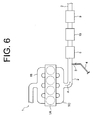
- the exhaust gas purification device of the second embodiment differs from that of the first embodiment in that the upstream and downstream catalytic layers are composed of an oxidizing catalyst and a fuel reforming catalyst, respectively.
- the upstream and downstream catalytic layers are composed of an oxidizing catalyst and a fuel reforming catalyst, respectively.
- Like or same parts or elements will be referred to by the same reference numerals as those in Figs. 1 though 5, and the description thereof will be omitted.
- Fig. 6 shows the structure of the exhaust gas purification device of the second preferred embodiment.
- the honeycomb support 5 is connected at the downstream side of the injector 3 in the direction indicated by an arrow A of Fig. 6 .
- an NSR catalyst 19 and a SCR catalyst 9 are connected serially in this order.
- the NSR catalyst 19 is similar to that of the downstream catalytic layer 8 in the first embodiment.
- upstream catalytic layers 17 composed of an oxidizing catalyst are formed on the upstream surfaces 5D of the porous walls 5C in the honeycomb support 5.
- downstream catalytic layers 18 composed of a fuel reforming catalyst are formed on the downstream surfaces 5E.
- the oxidizing catalyst of the upstream catalytic layers 17 includes a precious metal such as platinum (Pt), palladium (Pd), and the like, and serves to oxidize and burn particulate matter (hereinafter referred to as PM) contained in exhaust gas.
- the honeycomb support 5 is of a wall flow type in which exhaust gas flows through the porous walls 5C. As shown in Fig.
- the fuel reforming catalyst of the downstream catalytic layers 18 is similar to that of the upstream catalytic layers 7 in the first embodiment.
- carbon monoxide, hydrogen, hydrocarbon are generated as reducing agents for the NSR catalyst 19.
- Other structures are similar to those of the first embodiment.
- exhaust gas flowing into the honeycomb support 5 flows through the inlet cell 5A, the upstream catalytic layer 17, the porous wall 5C, and the downstream catalytic layer 18, serially in this order, into the outlet cell 5B.
- PM contained in exhaust gas is collected on the oxidizing catalyst of the upstream catalytic layer 17, as shown in Fig. 8 , and is burned to be removed by the function of the oxidizing catalyst.
- the heat generated when PM is burned is transferred to the downstream catalytic layer 18 through the porous wall 5C so as to heat the fuel reforming catalyst of the downstream catalytic layer 18.
- the exhaust gas from which PM is removed by the upstream catalytic layer 17 passes through the porous wall 5C and reaches the downstream catalytic layer 18. Since the injector 3 does not inject diesel fuel, the reaction over the fuel reforming catalyst of the downstream catalytic layer 18 does not occur.
- the exhaust gas passing through the downstream catalytic layer 18 is discharged to the outside of the honeycomb support 5, and passes through the NSR catalyst 19 connected downstream of the honeycomb support 5. Since the air-fuel ratio of the exhaust gas passing through the NSR catalyst 19 is in a lean state, the NSR catalyst 19 absorbs NO x temporarily, similar to that of the downstream catalytic layer 8 in the first embodiment. In case the air-fuel ratio of the exhaust gas is in a lean state, the NSR catalyst 19 does not generate ammonia, and the reaction over the SCR catalyst 9 does not occur.
- the injector 3 injects diesel fuel into the exhaust passage 2
- the mixed gas of exhaust gas and diesel fuel passes through the porous walls 5C of the honeycomb support 5.
- Part of diesel fuel in the mixed gas passes through the upstream catalytic layers 17 while not being burned, and reaches the downstream catalytic layers 18.
- the unburned diesel fuel reacts with oxygen and water vapor contained in the exhaust gas over the fuel reforming catalyst of the downstream catalytic layers 18 to generate carbon monoxide, hydrogen, and hydrocarbon as reducing agents for the NSR catalyst 19.
- the reaction is similar to that in the upstream catalytic layers 7 of the first embodiment.
- the unburned diesel fuel which reaches the downstream catalytic layers 18 is distributed uniformly in the whole exhaust gas. Therefore, the unburned diesel fuel is supplied uniformly to the entire fuel reforming catalyst of the downstream catalytic layers 18, thereby improving the reaction efficiency of the fuel reforming catalyst. Since the fuel reforming catalyst is heated by the heat generated when the oxidizing catalyst of the upstream catalytic layers 17 burns PM, the reaction efficiency of the fuel reforming catalyst is further improved.
- the exhaust gas in a rich state is discharged to the outside of the honeycomb support 5, and reaches the NSR catalyst 19. In this state, the exhaust gas includes diesel fuel which does not react over the fuel reforming catalyst of the downstream catalytic layers 18.
- the NSR catalyst 19 when the exhaust gas is in a rich state reacts similar to the NSR catalyst of the downstream catalytic layers 8 in the first embodiment.
- the upstream catalytic layers 17 are composed of the oxidizing catalyst and the downstream catalytic layers 18 are composed of the fuel reforming catalyst. Therefore, the single honeycomb support 5 has two different catalytic functions, thereby downsizing the exhaust gas purification device, similar to the first embodiment. Further, the unburned diesel fuel which passes through the upstream catalytic layers 17 is in an uniformly-distributed state in the exhaust gas when passing through the porous walls 5C. The diesel fuel is supplied uniformly to the entire downstream catalytic layers 18, thereby improving the reaction efficiency in the fuel reforming catalyst of the downstream catalytic layers 18.
- the upstream catalytic layers 17 are composed of the oxidizing catalyst which burns PM. Therefore, the heat generated when PM is burned is transferred to the downstream catalytic layers 18 through the porous walls 5C so as to heat the fuel reforming catalyst of the downstream catalytic layers 18. Therefore, the reaction efficiency of the fuel reforming catalyst is further improved.
- An exhaust gas purification device has an injector and a wall-flow type honeycomb support.
- the injector supplies fuel to the honeycomb support.
- the honeycomb support has a plurality of porous walls separating a plurality of inlet cells and a plurality of outlet cells.
- the exhaust gas flowing into the inlet cells flows through the porous walls into the outlet cells.
- Each porous wall has an upstream surface facing the inlet cell and a downstream surface facing the outlet cell.
- An upstream catalytic layer is formed on the upstream surface and a downstream catalytic layer is formed on the downstream surface.
- One of the upstream catalytic layer and the downstream catalytic layer is composed of a fuel reforming catalyst whose function is to reform the fuel to generate a reducing agent, and the other of the upstream catalytic layer and the downstream catalytic layer has a catalytic function which is different from the function of the fuel reforming catalyst.
Landscapes
- Engineering & Computer Science (AREA)
- Chemical & Material Sciences (AREA)
- Chemical Kinetics & Catalysis (AREA)
- Combustion & Propulsion (AREA)
- Health & Medical Sciences (AREA)
- Mechanical Engineering (AREA)
- General Engineering & Computer Science (AREA)
- Environmental & Geological Engineering (AREA)
- Toxicology (AREA)
- Analytical Chemistry (AREA)
- Biomedical Technology (AREA)
- General Chemical & Material Sciences (AREA)
- Oil, Petroleum & Natural Gas (AREA)
- Materials Engineering (AREA)
- Ceramic Engineering (AREA)
- Exhaust Gas After Treatment (AREA)
- Exhaust Gas Treatment By Means Of Catalyst (AREA)
- Processes For Solid Components From Exhaust (AREA)
Applications Claiming Priority (1)
| Application Number | Priority Date | Filing Date | Title |
|---|---|---|---|
| JP2007322241A JP4631902B2 (ja) | 2007-12-13 | 2007-12-13 | 排ガス浄化装置 |
Publications (1)
| Publication Number | Publication Date |
|---|---|
| EP2070580A2 true EP2070580A2 (fr) | 2009-06-17 |
Family
ID=40276190
Family Applications (1)
| Application Number | Title | Priority Date | Filing Date |
|---|---|---|---|
| EP08171176A Withdrawn EP2070580A2 (fr) | 2007-12-13 | 2008-12-10 | Dispositif de purification de gaz d'échappement |
Country Status (3)
| Country | Link |
|---|---|
| US (1) | US20090151340A1 (fr) |
| EP (1) | EP2070580A2 (fr) |
| JP (1) | JP4631902B2 (fr) |
Families Citing this family (4)
| Publication number | Priority date | Publication date | Assignee | Title |
|---|---|---|---|---|
| JP2010138783A (ja) * | 2008-12-11 | 2010-06-24 | Shin Ace:Kk | 内燃機関の後処理装置及び排気ガス浄化装置及びそれを用いた排気ガス浄化方法 |
| JP5553582B2 (ja) * | 2009-11-25 | 2014-07-16 | 日野自動車株式会社 | エンジンの排ガス浄化装置 |
| EP2707118B1 (fr) * | 2011-05-13 | 2019-12-04 | Basf Se | Filtre à suie catalysée à conception en couches |
| US11187127B2 (en) | 2019-06-28 | 2021-11-30 | Deere & Company | Exhaust gas treatment system and method with four-way catalyzed filter element |
Citations (1)
| Publication number | Priority date | Publication date | Assignee | Title |
|---|---|---|---|---|
| JP2006291847A (ja) | 2005-04-11 | 2006-10-26 | Toyota Motor Corp | ディーゼル排ガス浄化装置及びディーゼル排ガス浄化用触媒 |
Family Cites Families (10)
| Publication number | Priority date | Publication date | Assignee | Title |
|---|---|---|---|---|
| GB9919013D0 (en) * | 1999-08-13 | 1999-10-13 | Johnson Matthey Plc | Reactor |
| JP4742405B2 (ja) * | 2000-06-28 | 2011-08-10 | トヨタ自動車株式会社 | 燃料改質装置 |
| JP2002188435A (ja) * | 2000-10-12 | 2002-07-05 | Toyota Motor Corp | 排ガス浄化フィルタ |
| JP3872384B2 (ja) * | 2002-06-13 | 2007-01-24 | トヨタ自動車株式会社 | 排ガス浄化フィルタ触媒 |
| US7119044B2 (en) * | 2003-06-11 | 2006-10-10 | Delphi Technologies, Inc. | Multiple washcoats on filter substrate |
| JP2005146975A (ja) * | 2003-11-14 | 2005-06-09 | Toyota Motor Corp | パティキュレートフィルタ |
| JP4218559B2 (ja) * | 2004-03-19 | 2009-02-04 | トヨタ自動車株式会社 | ディーゼル排ガス浄化装置 |
| JP3885813B2 (ja) * | 2005-01-31 | 2007-02-28 | いすゞ自動車株式会社 | 排気ガス浄化装置の昇温方法及び排気ガス浄化システム |
| US20080072575A1 (en) * | 2006-09-21 | 2008-03-27 | Eaton Corporation | Catalyst to improve low temperature deNOx activity in a reformer-LNT exhaust aftertreatment system |
| KR100836367B1 (ko) * | 2006-11-21 | 2008-06-09 | 현대자동차주식회사 | 디젤엔진의 입자상물질과 질소산화물 저감을 위한 정화장치 |
-
2007
- 2007-12-13 JP JP2007322241A patent/JP4631902B2/ja not_active Expired - Fee Related
-
2008
- 2008-12-09 US US12/331,089 patent/US20090151340A1/en not_active Abandoned
- 2008-12-10 EP EP08171176A patent/EP2070580A2/fr not_active Withdrawn
Patent Citations (1)
| Publication number | Priority date | Publication date | Assignee | Title |
|---|---|---|---|---|
| JP2006291847A (ja) | 2005-04-11 | 2006-10-26 | Toyota Motor Corp | ディーゼル排ガス浄化装置及びディーゼル排ガス浄化用触媒 |
Also Published As
| Publication number | Publication date |
|---|---|
| US20090151340A1 (en) | 2009-06-18 |
| JP4631902B2 (ja) | 2011-02-16 |
| JP2009144587A (ja) | 2009-07-02 |
Similar Documents
| Publication | Publication Date | Title |
|---|---|---|
| US6832473B2 (en) | Method and system for regenerating NOx adsorbers and/or particulate filters | |
| US9689290B2 (en) | Reductant mixing system for an exhaust gas after-treatment device | |
| CN102057139B (zh) | 排放气体净化装置及排放气体净化系统 | |
| JP5141900B2 (ja) | 排気浄化装置 | |
| KR101986388B1 (ko) | Egr 회로에서 암모니아 슬립 촉매를 가지는 배기 시스템 | |
| US8128880B2 (en) | NOx reduction catalyst and exhaust system using the same | |
| US20110047994A1 (en) | Exhaust gas purification apparatus | |
| WO2004097197A2 (fr) | Systeme et procede de post-traitement au n0x pour moteurs a combustion interne | |
| EP2058480A1 (fr) | Système de purification de gaz d'échappement | |
| JP2010019239A (ja) | 排気浄化装置 | |
| JP2020045860A (ja) | 排ガス浄化装置 | |
| US7293409B2 (en) | Process and system for improving combustion and exhaust aftertreatment of motor vehicle engines | |
| EP2070580A2 (fr) | Dispositif de purification de gaz d'échappement | |
| JP5605578B2 (ja) | 排気浄化装置 | |
| US10329990B2 (en) | Asymmetric catalyst cone for swirl induction of exhaust gas flow | |
| JP4784761B2 (ja) | 排気浄化装置 | |
| JP2011033017A (ja) | 排気システム | |
| JP2008128046A (ja) | 排気浄化装置 | |
| US10041391B2 (en) | Apparatus for purifying exhaust gas | |
| JP5019069B2 (ja) | 排気浄化装置 | |
| JP2020045862A (ja) | 排ガス浄化装置 | |
| EP1959109B1 (fr) | Purificateur de gaz d'echappement pour moteur a combustion interne | |
| CN104704213B (zh) | 废气净化系统以及废气净化方法 | |
| JP4844766B2 (ja) | 排気浄化装置 | |
| JP2001140630A (ja) | 内燃機関の排ガス浄化装置 |
Legal Events
| Date | Code | Title | Description |
|---|---|---|---|
| PUAI | Public reference made under article 153(3) epc to a published international application that has entered the european phase |
Free format text: ORIGINAL CODE: 0009012 |
|
| 17P | Request for examination filed |
Effective date: 20081210 |
|
| AK | Designated contracting states |
Kind code of ref document: A2 Designated state(s): AT BE BG CH CY CZ DE DK EE ES FI FR GB GR HR HU IE IS IT LI LT LU LV MC MT NL NO PL PT RO SE SI SK TR |
|
| AX | Request for extension of the european patent |
Extension state: AL BA MK RS |
|
| RIC1 | Information provided on ipc code assigned before grant |
Ipc: B01D 53/94 20060101AFI20111207BHEP |
|
| STAA | Information on the status of an ep patent application or granted ep patent |
Free format text: STATUS: THE APPLICATION HAS BEEN WITHDRAWN |
|
| 18W | Application withdrawn |
Effective date: 20120201 |