EP2070641A2 - Système et procédé d'usinage adaptatif - Google Patents
Système et procédé d'usinage adaptatif Download PDFInfo
- Publication number
- EP2070641A2 EP2070641A2 EP08170601A EP08170601A EP2070641A2 EP 2070641 A2 EP2070641 A2 EP 2070641A2 EP 08170601 A EP08170601 A EP 08170601A EP 08170601 A EP08170601 A EP 08170601A EP 2070641 A2 EP2070641 A2 EP 2070641A2
- Authority
- EP
- European Patent Office
- Prior art keywords
- points
- component
- computer
- computer model
- deformed
- Prior art date
- Legal status (The legal status is an assumption and is not a legal conclusion. Google has not performed a legal analysis and makes no representation as to the accuracy of the status listed.)
- Withdrawn
Links
Images


Classifications
-
- F—MECHANICAL ENGINEERING; LIGHTING; HEATING; WEAPONS; BLASTING
- F01—MACHINES OR ENGINES IN GENERAL; ENGINE PLANTS IN GENERAL; STEAM ENGINES
- F01D—NON-POSITIVE DISPLACEMENT MACHINES OR ENGINES, e.g. STEAM TURBINES
- F01D5/00—Blades; Blade-carrying members; Heating, heat-insulating, cooling or antivibration means on the blades or the members
- F01D5/005—Repairing methods or devices
-
- B—PERFORMING OPERATIONS; TRANSPORTING
- B23—MACHINE TOOLS; METAL-WORKING NOT OTHERWISE PROVIDED FOR
- B23P—METAL-WORKING NOT OTHERWISE PROVIDED FOR; COMBINED OPERATIONS; UNIVERSAL MACHINE TOOLS
- B23P6/00—Restoring or reconditioning objects
- B23P6/002—Repairing turbine components, e.g. moving or stationary blades, rotors
- B23P6/007—Repairing turbine components, e.g. moving or stationary blades, rotors using only additive methods, e.g. build-up welding
-
- G—PHYSICS
- G05—CONTROLLING; REGULATING
- G05B—CONTROL OR REGULATING SYSTEMS IN GENERAL; FUNCTIONAL ELEMENTS OF SUCH SYSTEMS; MONITORING OR TESTING ARRANGEMENTS FOR SUCH SYSTEMS OR ELEMENTS
- G05B19/00—Program-control systems
- G05B19/02—Program-control systems electric
- G05B19/18—Numerical control [NC], i.e. automatically operating machines, in particular machine tools, e.g. in a manufacturing environment, so as to execute positioning, movement or co-ordinated operations by means of program data in numerical form
- G05B19/408—Numerical control [NC], i.e. automatically operating machines, in particular machine tools, e.g. in a manufacturing environment, so as to execute positioning, movement or co-ordinated operations by means of program data in numerical form characterised by data handling or data format, e.g. reading, buffering or conversion of data
- G05B19/4083—Adapting program, configuration
-
- G—PHYSICS
- G05—CONTROLLING; REGULATING
- G05B—CONTROL OR REGULATING SYSTEMS IN GENERAL; FUNCTIONAL ELEMENTS OF SUCH SYSTEMS; MONITORING OR TESTING ARRANGEMENTS FOR SUCH SYSTEMS OR ELEMENTS
- G05B19/00—Program-control systems
- G05B19/02—Program-control systems electric
- G05B19/18—Numerical control [NC], i.e. automatically operating machines, in particular machine tools, e.g. in a manufacturing environment, so as to execute positioning, movement or co-ordinated operations by means of program data in numerical form
- G05B19/4097—Numerical control [NC], i.e. automatically operating machines, in particular machine tools, e.g. in a manufacturing environment, so as to execute positioning, movement or co-ordinated operations by means of program data in numerical form characterised by using design data to control NC machines, e.g. CAD/CAM
-
- G—PHYSICS
- G05—CONTROLLING; REGULATING
- G05B—CONTROL OR REGULATING SYSTEMS IN GENERAL; FUNCTIONAL ELEMENTS OF SUCH SYSTEMS; MONITORING OR TESTING ARRANGEMENTS FOR SUCH SYSTEMS OR ELEMENTS
- G05B2219/00—Program-control systems
- G05B2219/30—Nc systems
- G05B2219/35—Nc in input of data, input till input file format
- G05B2219/35031—Redesign, use former design
-
- G—PHYSICS
- G05—CONTROLLING; REGULATING
- G05B—CONTROL OR REGULATING SYSTEMS IN GENERAL; FUNCTIONAL ELEMENTS OF SUCH SYSTEMS; MONITORING OR TESTING ARRANGEMENTS FOR SUCH SYSTEMS OR ELEMENTS
- G05B2219/00—Program-control systems
- G05B2219/30—Nc systems
- G05B2219/35—Nc in input of data, input till input file format
- G05B2219/35097—Generation of cutter path, offset curve
-
- G—PHYSICS
- G05—CONTROLLING; REGULATING
- G05B—CONTROL OR REGULATING SYSTEMS IN GENERAL; FUNCTIONAL ELEMENTS OF SUCH SYSTEMS; MONITORING OR TESTING ARRANGEMENTS FOR SUCH SYSTEMS OR ELEMENTS
- G05B2219/00—Program-control systems
- G05B2219/30—Nc systems
- G05B2219/45—Nc applications
- G05B2219/45147—Machining blade, airfoil
-
- G—PHYSICS
- G05—CONTROLLING; REGULATING
- G05B—CONTROL OR REGULATING SYSTEMS IN GENERAL; FUNCTIONAL ELEMENTS OF SUCH SYSTEMS; MONITORING OR TESTING ARRANGEMENTS FOR SUCH SYSTEMS OR ELEMENTS
- G05B2219/00—Program-control systems
- G05B2219/30—Nc systems
- G05B2219/49—Nc machine tool, till multiple
- G05B2219/49066—Geometric adaptive control
-
- G—PHYSICS
- G05—CONTROLLING; REGULATING
- G05B—CONTROL OR REGULATING SYSTEMS IN GENERAL; FUNCTIONAL ELEMENTS OF SUCH SYSTEMS; MONITORING OR TESTING ARRANGEMENTS FOR SUCH SYSTEMS OR ELEMENTS
- G05B2219/00—Program-control systems
- G05B2219/30—Nc systems
- G05B2219/50—Machine tool, machine tool null till machine tool work handling
- G05B2219/50214—Refurbish, refinish, reprofile, recondition, restore, rebuild profile
-
- Y—GENERAL TAGGING OF NEW TECHNOLOGICAL DEVELOPMENTS; GENERAL TAGGING OF CROSS-SECTIONAL TECHNOLOGIES SPANNING OVER SEVERAL SECTIONS OF THE IPC; TECHNICAL SUBJECTS COVERED BY FORMER USPC CROSS-REFERENCE ART COLLECTIONS [XRACs] AND DIGESTS
- Y02—TECHNOLOGIES OR APPLICATIONS FOR MITIGATION OR ADAPTATION AGAINST CLIMATE CHANGE
- Y02T—CLIMATE CHANGE MITIGATION TECHNOLOGIES RELATED TO TRANSPORTATION
- Y02T50/00—Aeronautics or air transport
- Y02T50/60—Efficient propulsion technologies, e.g. for aircraft
-
- Y—GENERAL TAGGING OF NEW TECHNOLOGICAL DEVELOPMENTS; GENERAL TAGGING OF CROSS-SECTIONAL TECHNOLOGIES SPANNING OVER SEVERAL SECTIONS OF THE IPC; TECHNICAL SUBJECTS COVERED BY FORMER USPC CROSS-REFERENCE ART COLLECTIONS [XRACs] AND DIGESTS
- Y10—TECHNICAL SUBJECTS COVERED BY FORMER USPC
- Y10T—TECHNICAL SUBJECTS COVERED BY FORMER US CLASSIFICATION
- Y10T29/00—Metal working
- Y10T29/49—Method of mechanical manufacture
- Y10T29/49316—Impeller making
- Y10T29/49318—Repairing or disassembling
-
- Y—GENERAL TAGGING OF NEW TECHNOLOGICAL DEVELOPMENTS; GENERAL TAGGING OF CROSS-SECTIONAL TECHNOLOGIES SPANNING OVER SEVERAL SECTIONS OF THE IPC; TECHNICAL SUBJECTS COVERED BY FORMER USPC CROSS-REFERENCE ART COLLECTIONS [XRACs] AND DIGESTS
- Y10—TECHNICAL SUBJECTS COVERED BY FORMER USPC
- Y10T—TECHNICAL SUBJECTS COVERED BY FORMER US CLASSIFICATION
- Y10T29/00—Metal working
- Y10T29/49—Method of mechanical manufacture
- Y10T29/49718—Repairing
- Y10T29/49732—Repairing by attaching repair preform, e.g., remaking, restoring, or patching
Definitions
- the invention relates generally to machining, and more particularly to a system and method for adaptive machining of components such as airfoils.
- the repair has been accomplished by machining away the damaged portion of the airfoils. Welding material was then manually deposited over the areas that had been machined away. The component was then machined by referencing a nominal model geometry in an attempt to reproduce the originally designed dimensions. Then, the component was hand finished, manually machined, in order to put the component in a serviceable condition.
- the method requires leaving a significant amount of material remaining (i.e., stock on) after the machining, which must be removed by a hand finishing process. This is due to the fact that no component, or blade within a component, is exactly at a nominal condition. The manual nature of the hand finishing process increases the cost and processing time of the repair. Finally, the method results in significant scrap.
- a method of repair includes removing a deformed portion of a component to define a native component portion and adding a replacement portion to the native component portion.
- the replacement portion is adaptively machined based on one or more parameters of the native component portion and based on one or more original design parameters of the component.
- a computer-implemented method includes receiving actual measurements of a component having an undesirable portion.
- the undesirable portion includes a deformation, a damaged portion, an undesirable shape, or a combination thereof.
- a computer model of the component is transformed based on the actual measurements and an original design intent, a new optimized design, or a combination thereof.
- a method of operating an adaptive machining system used for machining a component having a native component portion includes measuring a first set of points on the native component portion.
- An initial position of a computer model of the component is determined by rigid body transformation using the first set of points measured on the native component portion to form a transformed computer model.
- a second set of points is created on the transformed computer model.
- the second set of points on the transformed computer model corresponds with the first set of points on the native component portion.
- the transformed computer model is morphed by matching the first set of points with the second set of points.
- a method of operating an adaptive machining system used for machining a component having a native component portion includes creating a set of points in a built-up region of a transformed computer model representative of the native component portion.
- the method also includes applying a rigid body transformation and morphing to a plurality nominal cutter contact points of a nominal tool path so as to match the nominal cutter contact points with the set of points to form a plurality of deformed cutter contact points; wherein the plurality of deformed cutter contact points form a deformed tool path.
- a computer program to enable a controller operating an adaptive machining system for machining a component having a native component portion includes programming instructions stored in a tangible medium that enable the controller to receive actual measurements of a component having an undesirable portion.
- the undesirable portion includes a deformation, a damaged portion, an undesirable shape, or a combination thereof.
- the computer program also includes programming instructions stored in a tangible medium that enable the controller to transforming a computer model of the component based on the actual measurements and an original design intent, a new optimized design, or a combination thereof.
- FIG. 1 is a diagrammatical representation of a system for machining a component, for example an airfoil in accordance with an exemplary embodiment of the present technique
- FIG. 2 is a diagrammatical representation of a component surface having a warp patch and rigid patch in accordance with an exemplary embodiment of the present technique
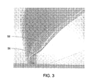
- FIG. 3 is a diagrammatical representation of nominal cutter contact points and morphed cutter contact points generated by an adaptive machining system in accordance with an exemplary embodiment of the present technique
- FIG. 4 is a diagrammatical representation of a flow chart illustrating exemplary steps involved in adaptive machining in accordance with an exemplary embodiment of the present technique.
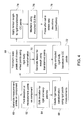
- FIG. 5 is a diagrammatical representation of a flow chart illustrating exemplary steps involved in adaptive machining using computer software (e.g., code stored on a tangible medium such as memory) in accordance with an exemplary embodiment of the present technique.
- computer software e.g., code stored on a tangible medium such as memory
- embodiments of the present technique provide a method for repairing a component, for example, an airfoil.
- the method includes removing a deformed portion of a component to define a native component portion.
- a replacement portion is added to the native component portion.
- the replacement portion is adaptively machined based on one or more parameters of the native component portion and also one or more original design parameters of the component.
- Other embodiments include a computer-implemented method, a tangible medium including computer-readable or machine-readable code, and a method of operating an adaptive machining system configured to repair a component based on at least in part on an original design intent, an optimum design, or a combination thereof, as well as present measurements (e.g., dimensions) of the component undergoing repair.
- the exemplary technique is applicable to a manufactured component having an undesirable shape, e.g. an airfoil with a blunted leading edge.
- the exemplary embodiments provide a technique for defining and machining the final shape of a repaired part.
- the exemplary technique employs a geometric model of the component.
- This model may be a CAD model or geometry constructed from a library of measurement data.
- the model may be a mesh model.
- the exemplary technique extrapolates information from measured points on the component and computer model to obtain a smooth "as-is" shape of the component.
- An initial position for the computer model is determined using a rigid body transformation computed using points measured on a surface of the native component portion. This provides an initial preferred location and orientation for shaping the newly added replacement portion.
- the transformed model geometry is then deformed using a function or process to smoothly blend the native component portion with the replacement portion.
- an exemplary adaptive machining system 10 used for machining a component 12 such as, for example, an airfoil of an aircraft engine, is illustrated in accordance with certain embodiments of the present technique.
- the system 10 includes a measurement system 14 configured to provide a first set of measurement points 16 on the component 12 having an undesirable portion.
- the undesirable portion includes a deformation, a damaged portion, an undesirable shape, or a combination thereof.
- the measurement points 16 are in the "x, y, z" coordinate system and is referred to as the "measured coordinate system".
- the measurement system 14 may include but not limited to a 5-axis milling machine, coordinate measuring machine (CMM), an x-ray scanning machine, an optical scanning machine, or an ultrasound scanning machine.
- CCMM coordinate measuring machine
- the system 10 also includes a computer model 18 (e.g., CAD model) of the component.
- the computer model 18 of the component is representative of the component geometry, shape, appearance, or a combination thereof, after undergoing a particular machining operation.
- the computer model 18 includes a second set of points in the "X, Y, Z" coordinate system and is referred to as the "computer model coordinate system".
- a computer 20 receives the first set of measurement points 16 and the computer model 18.
- the computer 20 is configured to determine the deviation between the first set of measurement points 16 on the component 12 and the second set of points of the computer model 18.
- the computer 20 classifies the first set of measurement points 16 on the component as "rigid patch” and "warp patch". Warp patch may be referred to as a region proximate to a repair zone of the component and rigid patch may be referred to as region away from the repair zone of the component. Rigid patch and warp patch are explained in greater detail with reference to subsequent figures below.
- the computer 20 generates a transformation model that approximates the deformation of the measured component 12 relative to the rigid patch.
- the computer 20 may be a general purpose computer such as a work station, a personal computer, or a machine controller.
- the computer 20 includes a processor 22 and a memory 24 including a random access memory (RAM), read only memory (ROM) and/or other components.
- the computer also includes a monitor 26, a keyboard 28, and a mouse device 30.
- the computer 20 operates under control of an operating system stored in the memory 24 to present data such as the set of measurement points 16 and the computer model 18 to an operator via the display screen of the monitor 26 and to accept and process commands from the operator via the keyboard 28 and the mouse device 30.
- the computer 20 generates the transformation model using one or more computer programs or applications (e.g., code or instructions) through a graphical user interface.
- a computer-readable medium e.g., one or more removable data storage devices 32 or a fixed data storage device 34, store the operating system, software applications, and other code configured to carry out the embodiments discussed in detail below.
- the storage devices 32 and 34 may include removable media drives and/or removable storage media, such as floppy discs, compact discs, digital video discs, flash memory, USB pen drives, and so forth.
- the storage devices 32 and 34 also may include hard disk drives.
- the system 10 also includes nominal tool paths 36 for operating a particular tool for machining the component 12.
- the computer 20 modifies the nominal tool paths 36 to the measured coordinate system of the component 12 according to the transformation model. Set forth below is also a more detailed discussion of how the computer 20 modifies the nominal tool paths 36.
- the modification of the nominal tool paths 28 results in deformed tool paths 38.
- a milling controller 40 uses the deformed tool paths 38 to process the component 12 by single pass machining or multi-pass machining.
- this figure is a diagrammatical representation of a component surface 42 of the component 12 having a native portion 44 and a built-up portion 46 in accordance with an exemplary embodiment of the present technique.
- the component 12 is an airfoil.
- the airfoil is used only for illustration of the disclosed embodiments, which are not limited to any particular type of component or application.
- the exemplary technique is equally applicable for repair applications of other suitable components.
- Repairing service parts often includes removing damaged sections of the part to produce a "native" part, and then replacing the damaged sections with either weld build-up or some other metallic substitute that may be machined away to produce a repaired part by smoothly blending the native part with the built-up part.
- Smooth blending of the repaired part includes accounting for rigid body errors in the original native part's shape or position, change in part geometry due to service, and any local warping induced by heating the native material during build up processes.
- the exemplary embodiments enable users to maintain or approach design intent, or to optimize their design based upon the shape of native (remaining) portion of the part before repair.
- the measurement system 14 is used to measure a first set of points 16 on the outer surface of the native portion 44 of the component 12.
- the computer model 18 is registered to the measured first set of points 16 on the native portion 44 of the component 12. It should be noted herein that image registration may be referred to as a process of transforming different sets of data into one coordinate system. Registration is required in order to be able to compare or integrate the data obtained from different measurements.
- the computer model 18 is subjected to rigid body transformation and morphing according to the measured first set of points 16.
- rigid body transformation may be referred to as a rigid body motion wherein an object may be moved from one position to another without altering the shape and size. Typical rigid body transformations involve translation, rotation, and reflection.
- Morphing may be referred to as a technique that changes (or morphs) one image into another through a seamless transition.
- the registering, rigid body transforming, and morphing are explained in greater detail with reference to subsequent flow charts.
- the computer 20 initially determines the deviation between the first set of measurement points 16 on the native component portion 44 and the second set of points of the computer model 18.
- a rigid patch 48 and a warp patch 50 are identified based on the deviation between the first set of points 16 on the native component portion 44 and the second set of points of the computer model 18.
- Points 52 in the region away from the built-up or heated zone 46 (points taken in thicker areas of the part) are referred to as the rigid patch 48.
- Points 54 proximate to the built-up region 46 are referred to as the warp patch 50.
- the rigid patch 48 provides an estimate of the shape change as well as errors in positioning and orientation of the component 12.
- the warp patch 50 may change shape significantly due to heat and service. Defining relevant patches on the native component portion 44 and manipulating the patches in a sequence, enables the present technique to obtain a smooth shape and properly defined features.
- this figure is a diagrammatical representation of nominal cutter contact points 56 and morphed cutter contact points 58 generated by the machining system in accordance with an exemplary embodiment of the present technique.
- the computer system 20 creates a set of virtual points in a built-up region 46 of the transformed computer model.
- the built-up region 46 of the transformed model corresponds with the built-up or replacement portion of the component 12.
- These virtual points may be manipulated for purposes of matching original design intent or creating new optimized shapes at the point of repair or manufacture.
- the nominal tool path 36 is registered to the set of virtual points on the transformed computer model.
- the nominal tool path 36 is then subjected to rigid body transformation and morphing according to the set of virtual points so as to match the nominal cutter contact points 56 of the nominal tool path 36 with the set of virtual points of the transformed computer model to form the plurality of morphed or deformed cutter contact points 58.
- the plurality of deformed cutter contact points 58 form a deformed tool path.
- the registering, rigid body, transforming, and morphing are explained in greater detail with reference to subsequent flow charts.
- the nominal cutter contact points 56 may be offset from the set of virtual points of the transformed computer model to form the deformed cutter points 58 of the deformed tool path so as to matching design intent or creating new optimized shapes at the point of repair or manufacture.
- the original design including geometry and/or dimensions of the component 12 may be adjusted based on actual measurements of the native component portion.
- the measurement system 14 generates a first set of measurement points 16 on the native component portion as represented by the step 60.
- the computer 20 receives the first set of measurement points 16 from the measurement system 14 and the computer model 18 of the component.
- the computer 20 determines the deviation between the first set of measurement points 16 on the native portion and the second set of points of the computer model 18 as represented by the step 62.
- the computer 20 classifies the first set of measurement points 16 on the component 12 into rigid patch 48 and warp patch 50 as represented by the step 64.
- the rigid patch 48 and warp patch 50 are identified based on the deviation between the first set of points 16 on the native portion and the second set of points of the computer model 18.
- the computer model 18 is then registered to the first set of measurement points 16.
- the computer model 18 is subjected to rigid body transformation and morphing according to the rigid patch 48 as represented by the step 66.
- the method further includes creating a set of corresponding points to drive morphing.
- each of the measured points 16 on the native portion 44 (in both rigid and warp patches 48 and 50) is matched with the closest point on the registered (transformed) computer model 18 as represented by step 70.
- Transforming the computer model 18 in the warp patch 48 includes creating a set of virtual points in the transformed model that are adjustable to achieve original design intent, new optimized design, or a combination thereof. The registering and rigid body transformation details are described in the subsequent paragraph.
- the computer 20 obtains a series of n (x, y, z) points measured on the native component portion 44.
- the computer 20 then generates a series of n pairings between the computer model 18 (X, Y, Z) points and the n series of measured (x, y, z) points 16 on the native component portion 44.
- Each of the n pairings between the computer model 18 and the measured series of n points 16 substantially correspond to each other.
- the computer 20 determines a plurality of mapping functions for mapping point locations from the computer model 18 to approximate measured locations of points on the native component portion 44.
- mapping functions such as polynomial functions, trigonometric functions or logical functions may be used as the mapping functions.
- the computer 20 optimizes the mapping functions to minimize the distance between the point locations of the computer model 18 to the measured locations of points 16 on the native component portion 44. Suitable mathematical functions may be used as the optimization function.
- the computer 20 transforms the point locations from the computer model 18 to the measured locations of points 16 on the native component portion 44.
- the optimized functions act as basis functions to transform the computer model coordinates and vectors to reflect the deformations measured in the native component portion 44. The transformation enables the original set of computer model 18 points to reside on or substantially near the actual measured points 16.
- the computer 20 generates a tensor for morph using the transformed computer model points as represented by the step 70.
- a tensor may be referred to as a generalized linear 'quantity' or 'geometrical entity' that can be expressed as a multidimensional array relative to a choice of basis of a particular space on which it is defined.
- Rigid body transformation is applied to cutter contact (CC) points of the nominal tool path 36 as represented by the step 72.
- the computer 20 modifies the nominal tool paths 36 to the measured coordinate system of the native component portion 44 according to the transformed computer model.
- the nominal tool paths 36 include a plurality of points and vectors in the nominal model coordinate system.
- the computer 20 then obtains the optimized mapping functions.
- the computer 20 applies the optimized mapping functions to the nominal tool paths 36.
- the nominal tool path 36 is registered to the set of virtual points created on the transformed computer model. In particular, for each point and vector that includes the nominal tool paths 36, the mapping functions move the tool path into an appropriate orientation and position with respect to the transformed model.
- the computer 20 After applying the optimized mapping functions to the nominal tool paths 36, the computer 20 generates the deformed tool paths.
- the tensor for morph is generated according to the deformed cutter contact points 58 of the deformed tool path 38 as represented by the step 74.
- the nominal cutter contact points 56 may be offset from the set of virtual points of the transformed computer model to form the deformed cutter points 58 of the deformed tool path 38 for the purpose of matching original design intent or creating new optimized shapes at the point of repair or manufacture.
- the modification of the nominal tool paths 36 results in the deformed tool paths 38, that the controller 40 uses to control a particular machining/manufacturing process.
- the controller 40 then uses the deformed tool paths 38 to machine the component 12 according to the original deign intent, new optimized design, or a combination thereof. After machining, the measurement points 16 on the machined component 12 may again be matched with the points on the computer model 18 to check for any deviations for verification purpose as represented by step 78.
- the exemplary technique disclosed herein may be used in a variety of numerical control processes such as drilling, milling, turning, inspecting, forging, non-contact measurement systems, surface finishing systems, or the like.
- this figure is a flow chart illustrating one exemplary embodiment of steps involved in adaptive machining using computer software (e.g., code stored on a tangible medium such as memory).
- a first set of measurement points 16 on a native component portion 44 is measured using a measurement tool.
- a computer 20 receives the first set of measurement points 16 from the measurement tool via a communication port as represented by the step 80.
- the computer 20 also receives a computer model 18 of the component 12 via the communication port.
- the computer 20 is then used to parse the points data to obtain a points file as represented by the step 82.
- the computer 20 determines the deviation between the first set of measurement points 16 on the native portion 44 and the second set of points of the computer model 18.
- the computer 20 classifies the first set of measurement points 16 on the component 12 into rigid patch 48 and warp patch 50.
- the computer 20 then runs a registration software program as represented by the step 84.
- the computer model 18 is registered to the first set of measurement points 16.
- the computer model 18 is subjected to rigid body transformation according to the rigid patch 48.
- the method further includes creating a set of corresponding points to drive morphing. In other words, each of the measured points on the native portion 44 (in both rigid and warp patches 48 and 50) is matched with the closest point on the registered (transformed) computer model 18.
- the computer 20 then runs a tensor program as represented by the step 86.
- the computer 20 generates a tensor for morph using the transformed computer model points.
- the computer 20 After transforming the computer model 18 according to the native component portion 44, the computer 20 then runs a tool path transformation program as represented by the step 88.
- the computer 20 modifies the nominal tool paths 36 to the measured coordinate system of the native component portion 44 according to the transformed computer model 18.
- the computer 20 After applying the optimized appropriate mapping functions to the nominal tool paths 36, the computer 20 generates the deformed tool paths 38.
- the tensor for morph is generated according to the deformed cutter contact points 58 of the deformed tool path 38.
- the deformed tool path 38 is then communicated to a machine tool via a communication port for machining the component 12 as represented by the step 90.
Landscapes
- Engineering & Computer Science (AREA)
- Mechanical Engineering (AREA)
- Human Computer Interaction (AREA)
- Manufacturing & Machinery (AREA)
- Physics & Mathematics (AREA)
- General Physics & Mathematics (AREA)
- Automation & Control Theory (AREA)
- General Engineering & Computer Science (AREA)
- Numerical Control (AREA)
- Electrical Discharge Machining, Electrochemical Machining, And Combined Machining (AREA)
- Perforating, Stamping-Out Or Severing By Means Other Than Cutting (AREA)
Applications Claiming Priority (1)
| Application Number | Priority Date | Filing Date | Title |
|---|---|---|---|
| US11/954,178 US8578579B2 (en) | 2007-12-11 | 2007-12-11 | System and method for adaptive machining |
Publications (1)
| Publication Number | Publication Date |
|---|---|
| EP2070641A2 true EP2070641A2 (fr) | 2009-06-17 |
Family
ID=40197247
Family Applications (1)
| Application Number | Title | Priority Date | Filing Date |
|---|---|---|---|
| EP08170601A Withdrawn EP2070641A2 (fr) | 2007-12-11 | 2008-12-03 | Système et procédé d'usinage adaptatif |
Country Status (5)
| Country | Link |
|---|---|
| US (2) | US8578579B2 (fr) |
| EP (1) | EP2070641A2 (fr) |
| JP (1) | JP5451049B2 (fr) |
| CN (1) | CN101456112B (fr) |
| SG (2) | SG172695A1 (fr) |
Cited By (15)
| Publication number | Priority date | Publication date | Assignee | Title |
|---|---|---|---|---|
| EP2317076A3 (fr) * | 2009-10-30 | 2011-08-24 | Alstom Technology Ltd | Procédé pour la réparation d'un composant de turbine à gaz |
| EP2317075A3 (fr) * | 2009-10-30 | 2011-08-24 | Alstom Technology Ltd | Procédé pour réparer un composant de turbine à gaz |
| EP2484481A1 (fr) * | 2011-02-03 | 2012-08-08 | Alstom Technology Ltd | Procédé de réparation ou de reconditionnement d'un élément Sévèrement endommagé, en particulier d'un élément de la région à gaz chaud d'une turbine à gaz |
| WO2014138219A1 (fr) * | 2013-03-05 | 2014-09-12 | Rolls-Royce Corporation | Usinage adaptatif de surfaces de composant et perçage de trou |
| WO2014138231A1 (fr) * | 2013-03-08 | 2014-09-12 | Rolls-Royce Corporation | Usinage adaptatif de composants |
| EP2781978A1 (fr) * | 2013-03-19 | 2014-09-24 | AV&R Vision | Procédé de détermination automatique d'une recette de finition d'un composant fabriqué |
| WO2014170919A1 (fr) * | 2013-04-15 | 2014-10-23 | Vea S.R.L. | Procédé de commande d'un système de forge, et système correspondant |
| GB2518682A (en) * | 2013-09-30 | 2015-04-01 | Bae Systems Plc | Information processing |
| CN104756027A (zh) * | 2012-09-25 | 2015-07-01 | 三菱重工业株式会社 | 加工装置的控制装置、加工装置和加工数据的校正方法 |
| US10030524B2 (en) | 2013-12-20 | 2018-07-24 | Rolls-Royce Corporation | Machined film holes |
| US10162331B2 (en) | 2015-03-02 | 2018-12-25 | Rolls-Royce Corporation | Removal of material from a surface of a dual walled component |
| WO2019002104A1 (fr) * | 2017-06-26 | 2019-01-03 | Capsix | Dispositif de gestion des deplacements d'un robot et robot de soin associe |
| EP3480426A1 (fr) * | 2017-11-02 | 2019-05-08 | Siemens Aktiengesellschaft | Usinage adaptatif d'une pièce à usiner ayant une section en forme de surface portante |
| EP3907572A1 (fr) * | 2020-05-07 | 2021-11-10 | Rolls-Royce plc | Procédé d'usinage d'un composant |
| FR3116456A1 (fr) * | 2020-11-23 | 2022-05-27 | Safran Aircraft Engines | Procede de reparation d’une piece de turbomachine et installation correspondante |
Families Citing this family (27)
| Publication number | Priority date | Publication date | Assignee | Title |
|---|---|---|---|---|
| US20100241264A1 (en) * | 2009-03-20 | 2010-09-23 | General Electric Company | System and method for manufacturing an in-process part |
| US8538574B2 (en) * | 2009-04-02 | 2013-09-17 | Dmg Electronics Gmbh | Method and apparatus for generating control data for controlling a tool on a machine tool |
| FR2947197B1 (fr) * | 2009-06-26 | 2011-07-15 | Snecma | Procede de fabrication d'une piece forgee avec polissage adaptatif |
| EP2537642A1 (fr) * | 2011-06-23 | 2012-12-26 | Raytheon BBN Technologies Corp. | Appareil de traitement dýinformations, programme et procédé de traitement dýinformations |
| US8788083B2 (en) * | 2011-07-22 | 2014-07-22 | Pratt & Whitney Canada Corp. | Compensation for process variables in a numerically-controlled machining operation |
| US8844132B2 (en) * | 2011-07-22 | 2014-09-30 | Pratt & Whitney Canada Corp. | Method of machining using an automatic tool path generator adapted to individual blade surfaces on an integrally bladed rotor |
| CN103603695B (zh) * | 2011-12-31 | 2016-06-22 | 无锡透平叶片有限公司 | 一种叶片合金槽及其加工方法 |
| US9003670B2 (en) * | 2012-03-08 | 2015-04-14 | United Technologies Corporation | System and method for measuring a workpiece relative to a common measurement coordinate system |
| FR2989608B1 (fr) * | 2012-04-24 | 2015-01-30 | Snecma | Procede d'usinage du bord de fuite d'une aube de turbomachine |
| US9031357B2 (en) * | 2012-05-04 | 2015-05-12 | Microsoft Technology Licensing, Llc | Recovering dis-occluded areas using temporal information integration |
| US9810069B2 (en) * | 2012-07-02 | 2017-11-07 | Ansaldo Energia Switzerland AG | Repair of a shrouded blade |
| US11047398B2 (en) | 2014-08-05 | 2021-06-29 | Energy Recovery, Inc. | Systems and methods for repairing fluid handling equipment |
| US10025289B2 (en) * | 2015-05-26 | 2018-07-17 | Pratt & Whitney Canada Corp. | System and method for automated part inspection |
| EP3098677B1 (fr) | 2015-05-27 | 2019-05-08 | Ansaldo Energia IP UK Limited | Procede d'usinage d'une piece sur une machine-outil a plusieurs axes entraines par un controleur nc et appareil pour la mise en uvre dudit procede |
| GB201607462D0 (en) * | 2016-04-29 | 2016-06-15 | Rolls Royce Plc | Adaptive repair method for aerofoil blades |
| US20170370220A1 (en) * | 2016-06-24 | 2017-12-28 | United Technologies Corporation | Customized blend limit for gas turbine engine airfoils |
| US10324426B2 (en) * | 2016-10-26 | 2019-06-18 | Embraer S.A. | Automated system and method to manufacture aeronautic junction parts |
| EP3321189B1 (fr) * | 2016-11-11 | 2021-03-03 | Airbus Operations GmbH | Procédé de reconditionnement d'une partie endommagée d'un composant et élément inséré |
| US20180216464A1 (en) * | 2017-01-31 | 2018-08-02 | General Electric Company | Method of repairing a blisk |
| EP3431211B1 (fr) * | 2017-07-20 | 2022-03-16 | General Electric Company | Procédés de fabrication d'un article hybride |
| CN108227627B (zh) * | 2017-12-18 | 2020-11-06 | 江苏科技大学 | 一种用于船用柴油机关键件的数控程序编制方法 |
| US10671047B2 (en) * | 2018-03-15 | 2020-06-02 | The Boeing Company | Composite structure repair system and method |
| TWI697425B (zh) * | 2019-02-26 | 2020-07-01 | 國立臺灣科技大學 | 車體修復系統及其方法 |
| US11828190B2 (en) | 2021-11-18 | 2023-11-28 | General Electric Company | Airfoil joining apparatus and methods |
| JP7424589B2 (ja) | 2021-11-19 | 2024-01-30 | 三菱重工業株式会社 | 加工方法 |
| CN115793572B (zh) * | 2022-11-09 | 2024-04-26 | 中国航发沈阳黎明航空发动机有限责任公司 | 一种航空机匣零件焊接凸台自适应加工方法 |
| WO2025120342A1 (fr) * | 2023-12-07 | 2025-06-12 | Liburdi Engineering Limited | Système et procédé de génération de trajet de soudage |
Family Cites Families (23)
| Publication number | Priority date | Publication date | Assignee | Title |
|---|---|---|---|---|
| US4883216A (en) | 1988-03-28 | 1989-11-28 | General Electric Company | Method for bonding an article projection |
| IL92428A (en) | 1989-02-08 | 1992-12-01 | Gen Electric | Fabrication of components by layered deposition |
| US5038014A (en) | 1989-02-08 | 1991-08-06 | General Electric Company | Fabrication of components by layered deposition |
| GB9408156D0 (en) | 1994-04-25 | 1994-06-15 | Turbine Blading Ltd | Turbine blade repair |
| DE19642980C1 (de) | 1996-10-18 | 1998-08-13 | Mtu Muenchen Gmbh | Verfahren zur Instandsetzung verschlissener Schaufelspitzen von Verdichter- und Turbinenschaufel |
| US6748112B1 (en) * | 1998-07-28 | 2004-06-08 | General Electric Company | Method and apparatus for finding shape deformations in objects having smooth surfaces |
| US6256546B1 (en) | 1998-09-28 | 2001-07-03 | General Electric Company | System and method for numerical control processing of an in-processing part |
| US6238187B1 (en) * | 1999-10-14 | 2001-05-29 | Lsp Technologies, Inc. | Method using laser shock peening to process airfoil weld repairs pertaining to blade cut and weld techniques |
| DE19963714A1 (de) | 1999-12-29 | 2001-07-05 | Abb Alstom Power Ch Ag | Verfahren zum Reparieren oder Aufbauen von rotierenden Komponenten einer Strömungsmaschine |
| US7082387B1 (en) * | 2000-02-08 | 2006-07-25 | International Business Machines Corporation | System and method for simultaneous construction of physical and CAD models |
| US6661930B1 (en) | 2000-04-25 | 2003-12-09 | General Electric Company | Method for nesting a computer model of a part with a computer model of a fixture |
| US20020094134A1 (en) * | 2001-01-12 | 2002-07-18 | Nafis Christopher Allen | Method and system for placing three-dimensional models |
| JP2004001633A (ja) | 2002-05-31 | 2004-01-08 | Takeo Kamigaki | 車輌修理の支援方法、車輌修理の支援プログラム、車輌修理の支援システム |
| US6912446B2 (en) | 2002-10-23 | 2005-06-28 | General Electric Company | Systems and methods for automated sensing and machining for repairing airfoils of blades |
| GB2401213A (en) | 2003-05-02 | 2004-11-03 | Delcam Plc | Altering a CAD model |
| US20050102835A1 (en) * | 2003-11-14 | 2005-05-19 | Trewiler Gary E. | Method for repairing gas turbine rotor blades |
| US20050217110A1 (en) | 2004-04-06 | 2005-10-06 | Topal Valeriy I | Deposition repair of hollow items |
| US6969826B2 (en) | 2004-04-08 | 2005-11-29 | General Electric Company | Welding process |
| US7472478B2 (en) | 2004-10-29 | 2009-01-06 | Honeywell International Inc. | Adaptive machining and weld repair process |
| GB0513899D0 (en) * | 2005-07-06 | 2005-08-10 | Airbus Uk Ltd | Program-controlled process |
| FR2889091B1 (fr) | 2005-07-29 | 2007-10-19 | Snecma | Procede de reparation d'une aube d'un disque aubage monobloc de turbomachine et eprouvette pour la mise en oeuvre du procede |
| GB0518435D0 (en) * | 2005-09-09 | 2005-10-19 | Airbus Uk Ltd | Improvements in computer-aided design of a component |
| WO2007033326A2 (fr) * | 2005-09-14 | 2007-03-22 | Welch Allyn, Inc. | Appareil medical comprenant une lentille adaptative |
-
2007
- 2007-12-11 US US11/954,178 patent/US8578579B2/en not_active Expired - Fee Related
-
2008
- 2008-11-24 SG SG2011042413A patent/SG172695A1/en unknown
- 2008-11-24 SG SG200808687-8A patent/SG153738A1/en unknown
- 2008-12-03 EP EP08170601A patent/EP2070641A2/fr not_active Withdrawn
- 2008-12-08 JP JP2008311757A patent/JP5451049B2/ja not_active Expired - Fee Related
- 2008-12-11 CN CN200810187170.XA patent/CN101456112B/zh not_active Expired - Fee Related
-
2013
- 2013-10-08 US US14/048,174 patent/US20140041183A1/en not_active Abandoned
Cited By (24)
| Publication number | Priority date | Publication date | Assignee | Title |
|---|---|---|---|---|
| EP2317075A3 (fr) * | 2009-10-30 | 2011-08-24 | Alstom Technology Ltd | Procédé pour réparer un composant de turbine à gaz |
| EP2317076A3 (fr) * | 2009-10-30 | 2011-08-24 | Alstom Technology Ltd | Procédé pour la réparation d'un composant de turbine à gaz |
| EP2484481A1 (fr) * | 2011-02-03 | 2012-08-08 | Alstom Technology Ltd | Procédé de réparation ou de reconditionnement d'un élément Sévèrement endommagé, en particulier d'un élément de la région à gaz chaud d'une turbine à gaz |
| CH704448A1 (de) * | 2011-02-03 | 2012-08-15 | Alstom Technology Ltd | Verfahren zum Reparieren bzw. Rekonditionieren eines stark beschädigten Bauteils, insbesondere aus dem Heissgasbereich einer Gasturbine. |
| US8910361B2 (en) | 2011-02-03 | 2014-12-16 | Alstom Technology Ltd. | Method for repairing or reconditioning a badly damaged component, in particular from the hot gas region of a gas turbine |
| US9897993B2 (en) | 2012-09-25 | 2018-02-20 | Mitsubishi Heavy Industries, Ltd. | Control device for machining apparatus, machining apparatus, and correction method of machining data |
| CN104756027A (zh) * | 2012-09-25 | 2015-07-01 | 三菱重工业株式会社 | 加工装置的控制装置、加工装置和加工数据的校正方法 |
| EP2884360A4 (fr) * | 2012-09-25 | 2015-12-23 | Mitsubishi Heavy Ind Ltd | Dispositif de commande pour dispositif d'usinage, dispositif d'usinage, et procédé de correction pour données d'usinage |
| WO2014138219A1 (fr) * | 2013-03-05 | 2014-09-12 | Rolls-Royce Corporation | Usinage adaptatif de surfaces de composant et perçage de trou |
| US9817389B2 (en) | 2013-03-05 | 2017-11-14 | Rolls-Royce Corporation | Adaptively machining component surfaces and hole drilling |
| US9817393B2 (en) | 2013-03-08 | 2017-11-14 | Rolls-Royce Corporation | Adaptive machining of components |
| WO2014138231A1 (fr) * | 2013-03-08 | 2014-09-12 | Rolls-Royce Corporation | Usinage adaptatif de composants |
| EP2781978A1 (fr) * | 2013-03-19 | 2014-09-24 | AV&R Vision | Procédé de détermination automatique d'une recette de finition d'un composant fabriqué |
| US10482186B2 (en) | 2013-03-19 | 2019-11-19 | Av&R Vision And Robotics Inc. | Method for automatically determining a finishing recipe of a manufactured component |
| WO2014170919A1 (fr) * | 2013-04-15 | 2014-10-23 | Vea S.R.L. | Procédé de commande d'un système de forge, et système correspondant |
| GB2518682A (en) * | 2013-09-30 | 2015-04-01 | Bae Systems Plc | Information processing |
| US10030524B2 (en) | 2013-12-20 | 2018-07-24 | Rolls-Royce Corporation | Machined film holes |
| US10162331B2 (en) | 2015-03-02 | 2018-12-25 | Rolls-Royce Corporation | Removal of material from a surface of a dual walled component |
| WO2019002104A1 (fr) * | 2017-06-26 | 2019-01-03 | Capsix | Dispositif de gestion des deplacements d'un robot et robot de soin associe |
| US11338443B2 (en) | 2017-06-26 | 2022-05-24 | Capsix | Device for managing the movements of a robot, and associated treatment robot |
| EP3480426A1 (fr) * | 2017-11-02 | 2019-05-08 | Siemens Aktiengesellschaft | Usinage adaptatif d'une pièce à usiner ayant une section en forme de surface portante |
| EP3907572A1 (fr) * | 2020-05-07 | 2021-11-10 | Rolls-Royce plc | Procédé d'usinage d'un composant |
| US11883927B2 (en) | 2020-05-07 | 2024-01-30 | Rolls-Royce Plc | Method of machining a component |
| FR3116456A1 (fr) * | 2020-11-23 | 2022-05-27 | Safran Aircraft Engines | Procede de reparation d’une piece de turbomachine et installation correspondante |
Also Published As
| Publication number | Publication date |
|---|---|
| CN101456112A (zh) | 2009-06-17 |
| US8578579B2 (en) | 2013-11-12 |
| SG172695A1 (en) | 2011-07-28 |
| JP5451049B2 (ja) | 2014-03-26 |
| CN101456112B (zh) | 2014-03-26 |
| US20140041183A1 (en) | 2014-02-13 |
| US20090144980A1 (en) | 2009-06-11 |
| JP2009151770A (ja) | 2009-07-09 |
| SG153738A1 (en) | 2009-07-29 |
Similar Documents
| Publication | Publication Date | Title |
|---|---|---|
| US8578579B2 (en) | System and method for adaptive machining | |
| Li et al. | An integrated approach of reverse engineering aided remanufacturing process for worn components | |
| JP7067721B2 (ja) | 加工物上に付加的に印刷するための付加製造システム及び較正方法 | |
| EP3689506B1 (fr) | Systèmes de fabrication additive et procédés d'impression additive sur pièces | |
| JP7208346B2 (ja) | 付加製造システム、及びワークピース上に付加印刷するためのcadモデルを生成する方法 | |
| Zhou et al. | Adaptive direct slicing with non-uniform cusp heights for rapid prototyping | |
| CN105739440A (zh) | 一种宽弦空心风扇叶片的自适应加工方法 | |
| CN112046005B (zh) | 在工件上进行预处理和增材打印的增材制造系统和方法 | |
| CN109343468B (zh) | 一种基于投影偏置的叶片多轴轨迹生成方法 | |
| Zhao et al. | Measurement-based geometric reconstruction for milling turbine blade using free-form deformation | |
| CN115146405B (zh) | 一种基于非刚性配准变形的薄壁零件模型重构方法 | |
| Chowdary et al. | 3D CAD model reconstruction and fast prototyping of rotational parts: a reverse engineering approach | |
| Young et al. | An integrated machining approach for a centrifugal impeller | |
| Zhu et al. | Geometric conditions for tangent continuity of swept tool envelopes with application to multi-pass flank milling | |
| Wang et al. | A supplementary processing method of residual material in impeller plunge milling | |
| Feng et al. | Prediction and reconstruction of edge shape in adaptive machining of precision forged blade | |
| CN116859822A (zh) | 刀路规划方法、装置、电子设备及可读存储介质 | |
| US7097540B1 (en) | Methods and apparatus for machining formed parts to obtain a desired profile | |
| CN118204977A (zh) | 一种大型结构件焊缝打磨机器人自主编程方法及设备 | |
| US12596345B2 (en) | Forming stylus tool design and toolpath generation module for 3 axis computer numerical control manufacturing processes | |
| Mane et al. | Adaptive tool path planning strategy for 5-axis CNC machining of free form surfaces | |
| KR102641382B1 (ko) | 기상 측정을 활용한 형상 오차 보정 장치 및 그 방법 | |
| Liu et al. | Five-axis numerical control helical tool path generation for bullnose milling cutters finishing machining blades | |
| Shan et al. | A novel spiral machining approach for blades modeled with four patches | |
| Gray | g for 3%%-Axis 5-Axis Surface Machining |
Legal Events
| Date | Code | Title | Description |
|---|---|---|---|
| PUAI | Public reference made under article 153(3) epc to a published international application that has entered the european phase |
Free format text: ORIGINAL CODE: 0009012 |
|
| AK | Designated contracting states |
Kind code of ref document: A2 Designated state(s): AT BE BG CH CY CZ DE DK EE ES FI FR GB GR HR HU IE IS IT LI LT LU LV MC MT NL NO PL PT RO SE SI SK TR |
|
| AX | Request for extension of the european patent |
Extension state: AL BA MK RS |
|
| STAA | Information on the status of an ep patent application or granted ep patent |
Free format text: STATUS: THE APPLICATION IS DEEMED TO BE WITHDRAWN |
|
| 18D | Application deemed to be withdrawn |
Effective date: 20170701 |