EP2070660A2 - Appareil de presse hydraulique - Google Patents
Appareil de presse hydraulique Download PDFInfo
- Publication number
- EP2070660A2 EP2070660A2 EP08171021A EP08171021A EP2070660A2 EP 2070660 A2 EP2070660 A2 EP 2070660A2 EP 08171021 A EP08171021 A EP 08171021A EP 08171021 A EP08171021 A EP 08171021A EP 2070660 A2 EP2070660 A2 EP 2070660A2
- Authority
- EP
- European Patent Office
- Prior art keywords
- hydraulic
- pressing device
- pot
- piston
- pressure
- Prior art date
- Legal status (The legal status is an assumption and is not a legal conclusion. Google has not performed a legal analysis and makes no representation as to the accuracy of the status listed.)
- Granted
Links
Images





Classifications
-
- B—PERFORMING OPERATIONS; TRANSPORTING
- B25—HAND TOOLS; PORTABLE POWER-DRIVEN TOOLS; MANIPULATORS
- B25B—TOOLS OR BENCH DEVICES NOT OTHERWISE PROVIDED FOR, FOR FASTENING, CONNECTING, DISENGAGING, OR HOLDING
- B25B27/00—Hand tools, specially adapted for fitting together or separating parts or objects whether or not involving some deformation, not otherwise provided for
- B25B27/02—Hand tools, specially adapted for fitting together or separating parts or objects whether or not involving some deformation, not otherwise provided for for connecting objects by press fit or detaching same
- B25B27/10—Hand tools, specially adapted for fitting together or separating parts or objects whether or not involving some deformation, not otherwise provided for for connecting objects by press fit or detaching same inserting fittings into hoses
-
- B—PERFORMING OPERATIONS; TRANSPORTING
- B25—HAND TOOLS; PORTABLE POWER-DRIVEN TOOLS; MANIPULATORS
- B25B—TOOLS OR BENCH DEVICES NOT OTHERWISE PROVIDED FOR, FOR FASTENING, CONNECTING, DISENGAGING, OR HOLDING
- B25B27/00—Hand tools, specially adapted for fitting together or separating parts or objects whether or not involving some deformation, not otherwise provided for
- B25B27/14—Hand tools, specially adapted for fitting together or separating parts or objects whether or not involving some deformation, not otherwise provided for for assembling objects other than by press fit or detaching same
- B25B27/146—Clip clamping hand tools
Definitions
- the invention relates to a hydraulic pressing device with a fixed part and a moving part, wherein the moving part is moved by a hydraulic piston relative to the fixed part and by means of a return spring in an initial position réellebewegbar, wherein the return movement in response to a predetermined, adjustable pressing pressure by opening a return valve he follows.
- the invention has the object, the known hydraulic pressing device to design and further develop that pressing operations that require different compression pressures can be performed reliably.
- the adjustable pressing pressure is gradually adjustable. According to the invention it has been recognized that a desired adjustability of the pressing pressure by a stepwise adjustability of the requirement quite particularly is to carry out reliable pressings or a duty cycle of the device at different pressing pressures.
- a particularly elongated pressing device that for adjusting the predetermined pressing pressure in addition to otherwise formed on the device
- Pressure / tilting and / or sliding switches designed as a rotary switch adjusting part is provided, which is arranged circumferentially offset to the pressure / tilt and / or slide switches and has a molding for actuation by means of an aid.
- this rotary switch is also preferably circumferentially offset from said other switches (which may already be circumferentially offset from one another).
- While the first-mentioned switches preferably lie on a common longitudinal plane (it can also be a longitudinal plane area), although possibly offset by 180 ° from one another, rotated about a longitudinal axis of the device, the newly provided rotary switch is as it were in between. For example, in a range of a rotation of 70 to 110 °, preferably about 90 °, corresponding to the longitudinal axis, starting from one of the other switches. Seen in the direction of the working head, the rotary switch, starting from the upper switches, preferably offset by a left-hand rotation. As a result, a high degree of security is achieved that no accidental or casual adjustment of the pressure is made.
- the rotary switch is provided at its actuating end with a bore into which an aid can be introduced.
- the aid can be an actuating ring.
- the aid in particular the said actuating ring, readily held captive in the molding.
- the actuating ring is pivotable and preferably also rotatable (in its circumferential direction, ie in the sense of a penetration through the operating end) supported on the actuating end. He interspersed for this purpose designed as a hole mounting hole in the operating end. With the help of the force transmission achieved by the actuating ring, the rotary switch can be suitably operated. Since such an actuating ring but down in the unused state in a not directly suitable for handling position, the desired security is also given.
- this embodiment may be provided combined with the stepwise adjustability.
- the pressing pressure can be adjusted without tools, ie without a means which is to be carried separately in the sense of a hand tool, such as a screwdriver or a pair of pliers. This does not mean that it can be adjusted by means of an everyday aid, as mentioned, such as a coin.
- the adjustment of the pressing pressure takes place by means of an adjustment part designed as a rotatable step portion.
- the step part already has the gradation, which corresponds to the desired stepwise adjustment of the pressing pressure.
- the adjustment of the pressing pressure can be done additionally or alternatively by a self-locking screw; this has, for example, in his Beaufschlagungsspitze a Schneckenradförmige design.
- the adjusting part has a slot guide in its outside projecting area.
- the adjustment can also be provided only acting on the step part or the screw or other adjustment.
- the adjustment of the pressing pressure by adjusting the trigger pressure of the return valve takes place.
- the actuating part acts on an overflow pot of the spring of the check valve.
- the Studentsfangtopf may in principle, if he is not hindered by the adjustment movement, move freely in the outward direction. There may be an absolute limit, such as by a separately trained stop provided. This can have about assembly or disassembly technical advantages.
- valve pot of the return valve against which a valve tip exhibiting valve stem is spring-supported, is received freely movable in a receiving cylinder.
- the valve pot can accordingly move freely in the direction of the cylinder axis of the receiving cylinder. In both directions. However, it is provided that only the movement of the valve plug is prevented against the closing direction of the valve. And by the adjustment already described. The movement hindrance can be changed accordingly with regard to the position of the valve pot in the axial direction of the cylinder.
- said return valve to which the adjustment, bpw. the rotary switch, acts, is arranged with a direction of movement corresponding to the alignment of the longitudinal axis of the device, this adjusting part relative to a central longitudinal axis of the pressing device in the region of the return valve skew, to arrange in a skewed hole.
- the bore runs skewed to the longitudinal axis of the pressing device. In a projection thus intersect the adjustment and the central longitudinal axis, while they pass in a cross section perpendicular to the central longitudinal axis of the device to each other.
- the invention further relates to a hydraulic pressing device with a pump for conveying hydraulic means, a housing, a fixed and a moving part, wherein the moving part is moved by a hydraulic piston relative to the fixed part and by means of a return spring in an initial position NASAbewegbar.
- the tension piston is designed as a hollow piston. It is further preferred that the return spring is supported on the one hand on the pot bottom of the cup part (on the inside) and on the other hand in the tension piston.
- the pulling piston is assigned according to the pot bottom preferably open, in which case the compression spring in the pulling piston - possibly over a substantial part of its length - may be introduced. This also provides a secure hold and secure reception of the resetting of the piston serving compression spring.
- the cup part is prevented from moving by a counter-holder screwed to the housing.
- the cup part is subjected to a considerable force during the operation of the pressing device, it performs no or no substantial axial movement. The forces are rather absorbed in the housing of the device.
- the surface acted on by the hydraulic means on the pot part is larger than the area acted upon by the hydraulic fluid on the pulling piston. A correspondingly small proportion of the force is actually then converted into traction. Obviously, this also gives constructive freedom to vary this ratio relatively easily.
- the hydraulic fluid preferably flows around the pot part.
- the hydraulic fluid can flow through a gap between a cylinder portion of the housing in which the pot part is arranged, and an inner wall of the cylinder part.
- the cup part is arranged without a seal except for the cup part itself formed sealing projections or sealing ribs.
- the cup part does not require a separate seal, for example in the sense of an O-ring, to the receiving cylinder and also not with respect to the pulling piston arranged therein.
- the seal to the outside can be given in the area of the counter-holder.
- the hydraulic medium-acting surface of the tension piston is further preferably formed annular.
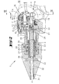
- a hydraulic pressing device 1 with -. Fig. 2 a fixed part 2 and a moving part 3.
- the Movement part 3 is moved relative to the fixed part 2 by a trained as a tension piston hydraulic piston 4.
- the movement part 3 is by means of the return spring 5, which acts in the embodiment directly on the tension piston 4, moved back into its initial position.
- the return movement of the moving part 3 or of the tensioning piston 4 takes place upon reaching a predetermined pressing pressure.
- the return valve opens 6.
- the opening of the return valve 6 is achieved by reaching a threshold pressure, as in detail in the already mentioned above EP 0 944 937 is described.
- the return movement could also be triggered according to an embodiment, such as in the DE 195 35 691 C1 is described.
- the pressing pressure at which the triggering occurs, is gradually adjustable by means of a step portion 7.
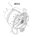
- the step part is rotatably arranged. It is elongated in itself, with a step-loading tip 8 and an outwardly projecting freely projecting actuating end 9. In its outwardly projecting region, it may have a slot guide. Due to such a slot guide, it can be rotated ver example, by inserting a coin or other disc-shaped part or flat part. On the other hand, twisting is only relatively difficult with the fingers. This supports the goal that only conscious and easy pressure adjustment should be performed.
- the actuating end 9 is provided with an actuating ring 10, which passes 29enkbar and preferably rotatable formed in the operating end 9 mounting hole.
- the step part 7 can be twisted handling favorable.
- a slide switch 11 a (emergency switch), which can also be designed as a rocker switch, or a pressure switch 12 (this may alternatively be designed as a rocker switch), which for actuating or for emergency service.
- a locking button 13 to remove the battery unit.
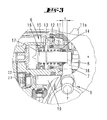
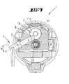
- the operation is in detail when comparing the Fig. 4 . 5 and 7 , 8 and 3, 6, respectively.
- the position of the step part is in the Fig. 4 and 5 , as well as 7 and 8 respectively.
- the step portion 7 has an eccentric to its central axis YY - in a basic training as a rotationally symmetric part - arranged operating tip 8, which is formed as a rectangular flat part, with three narrow sides and two broad sides.
- the step part acts with a narrow side of the operating tip on the valve pot 11 of the return valve 6.
- the broad side after the step part has been swiveled by 90 °.
- the valve pot 11 by means of its outer bottom 18, constantly at the operating tip of the step part. Depending on the rotational position of the step portion of the valve pot 11 is moved out relative to the cylinder 12 more or less outward.
- a In the Fig. 2 . 3 and 6 is the example possible travel path indicated by a.
- the closed state of the return valve 6 results depending on the position of the step portion, a larger or smaller distance between the given here through the passage body 14, the first abutment of the compression spring, and given by the stop member second abutment of the compression spring. Both abutments are movable.
- the first abutment is operationally movable automatically.
- the other abutment is deliberately flexible.
- valve stem 11 is axially movable relative to the annular bodies 14.
- a pump piston 19 is arranged axially parallel to the valve stem 16, which is essentially parallel to a central longitudinal axis of the pressing device.
- the pump is preferably a multi-stage pump, as for example in the WO 99/04165 is described.
- the disclosure of this document is hereby also incorporated in full content in the disclosure of the present application, also for the purpose to include features of this prior art document, in particular with regard to the formation of the pump in the claims of the present application.
- a pot part 20 is arranged within the fixed part or of the housing.
- the pot bottom 21 of the cup portion 20 is arranged associated with the pump. Obviously, a gap-like space 22 has remained in which the hydraulic fluid is first pumped.
- the cup part is formed on its cylindrical pot wall with two axially spaced flat ribs 23, 24, which flat ribs are formed interrupted over its circumference. These interruptions are related to the illustration in FIG Fig. 2 can be recognized by the fact that opposite to the projections, to which the reference lines of the reference numerals 22, 23 rich, no projections are shown.
- the counter holder 26 has, in addition to its holding function sealing function.
- the sealing rings 27, 28 are provided for a seal inwardly with respect to the pulling piston 4 and out to the housing wall.
- the counter-holder 26 is further covered by a screw cap 29, which ultimately provides the tensile connection to the housing 2.
- the space 25 is reached by a recess made in the wall of the counter-holder or of the cup part.
- a recess made in the wall of the counter-holder or of the cup part.
- Hydraulic fluid flows via the space 25 onto the annular surface 30 of the pulling piston so that it is moved downward or in the direction of the pump when pressure is applied. This against the action of the compression spring. 5
- a pipe part 31 is rigidly connected in the embodiment.
- the component 31 is tightened accordingly, ie moved together with the pulling piston 4 in the direction of the pump or in the direction inwards.
- a rod part 32 is further arranged centrally to the tube part 31, which is schraubhalteert in a transverse pin 33.
- these two parts can be moved relative to each other, wherein the rod member 32 is actually stationary.
- the embodiment of the tube-like design and with the pulling piston 4, for example, welded movement part 3 has for this purpose, to enable a relative movement to the standing part 32 and the cross pin 33, a slot 34. The same can be used for setting a rivet or the like.
Landscapes
- Engineering & Computer Science (AREA)
- Mechanical Engineering (AREA)
- Reciprocating Pumps (AREA)
- Press Drives And Press Lines (AREA)
- Details Of Reciprocating Pumps (AREA)
Applications Claiming Priority (2)
| Application Number | Priority Date | Filing Date | Title |
|---|---|---|---|
| DE102007060933 | 2007-12-14 | ||
| DE102008023719A DE102008023719A1 (de) | 2007-12-14 | 2008-05-15 | Hydraulisches Pressgerät |
Publications (3)
| Publication Number | Publication Date |
|---|---|
| EP2070660A2 true EP2070660A2 (fr) | 2009-06-17 |
| EP2070660A3 EP2070660A3 (fr) | 2010-11-03 |
| EP2070660B1 EP2070660B1 (fr) | 2012-09-26 |
Family
ID=40448418
Family Applications (1)
| Application Number | Title | Priority Date | Filing Date |
|---|---|---|---|
| EP20080171021 Not-in-force EP2070660B1 (fr) | 2007-12-14 | 2008-12-09 | Appareil de presse hydraulique |
Country Status (1)
| Country | Link |
|---|---|
| EP (1) | EP2070660B1 (fr) |
Families Citing this family (1)
| Publication number | Priority date | Publication date | Assignee | Title |
|---|---|---|---|---|
| DE202024105873U1 (de) | 2024-10-11 | 2026-01-13 | Novopress Gmbh Pressen Und Presswerkzeuge & Co. Kommanditgesellschaft | Pressgerät |
Citations (6)
| Publication number | Priority date | Publication date | Assignee | Title |
|---|---|---|---|---|
| DE19535691C1 (de) | 1995-09-26 | 1997-01-23 | Rothenberger Werkzeuge Masch | Hydraulisch angetriebenes Handwerkzeug |
| WO1999004165A1 (fr) | 1997-07-19 | 1999-01-28 | Gustav Klauke Gmbh | Pompe a pistons |
| EP0944937A1 (fr) | 1997-10-15 | 1999-09-29 | Gustav Klauke GmbH | Dispositif de pressage hydraulique et son procede de fonctionnement |
| DE19834003A1 (de) | 1998-07-29 | 2000-02-03 | Adam Gerich | Montagehilfe für eine Befestigungsvorrichtung, insbesondere für Schlauch- oder Rohranschlüsse |
| WO2003084719A2 (fr) | 2002-04-10 | 2003-10-16 | Gustav Klauke Gmbh | Appareil de pressage electrohydraulique et procede pour faire fonctionner un tel appareil |
| DE102006026552A1 (de) | 2006-06-08 | 2007-12-13 | Gustav Klauke Gmbh | Verfahren zum Betreiben eines hydraulischen Verpressgerätes sowie hydraulisches Verpressgerät mit einer Hydraulikpumpe |
Family Cites Families (1)
| Publication number | Priority date | Publication date | Assignee | Title |
|---|---|---|---|---|
| DE202004000215U1 (de) * | 2004-01-08 | 2004-04-01 | Novopress Gmbh Pressen Und Presswerkzeuge & Co Kg | Handgeführtes Preßgerät |
-
2008
- 2008-12-09 EP EP20080171021 patent/EP2070660B1/fr not_active Not-in-force
Patent Citations (7)
| Publication number | Priority date | Publication date | Assignee | Title |
|---|---|---|---|---|
| DE19535691C1 (de) | 1995-09-26 | 1997-01-23 | Rothenberger Werkzeuge Masch | Hydraulisch angetriebenes Handwerkzeug |
| WO1999004165A1 (fr) | 1997-07-19 | 1999-01-28 | Gustav Klauke Gmbh | Pompe a pistons |
| EP0944937A1 (fr) | 1997-10-15 | 1999-09-29 | Gustav Klauke GmbH | Dispositif de pressage hydraulique et son procede de fonctionnement |
| EP0944937B1 (fr) | 1997-10-15 | 2002-03-27 | Gustav Klauke GmbH | Dispositif de pressage hydraulique |
| DE19834003A1 (de) | 1998-07-29 | 2000-02-03 | Adam Gerich | Montagehilfe für eine Befestigungsvorrichtung, insbesondere für Schlauch- oder Rohranschlüsse |
| WO2003084719A2 (fr) | 2002-04-10 | 2003-10-16 | Gustav Klauke Gmbh | Appareil de pressage electrohydraulique et procede pour faire fonctionner un tel appareil |
| DE102006026552A1 (de) | 2006-06-08 | 2007-12-13 | Gustav Klauke Gmbh | Verfahren zum Betreiben eines hydraulischen Verpressgerätes sowie hydraulisches Verpressgerät mit einer Hydraulikpumpe |
Also Published As
| Publication number | Publication date |
|---|---|
| EP2070660B1 (fr) | 2012-09-26 |
| EP2070660A3 (fr) | 2010-11-03 |
Similar Documents
| Publication | Publication Date | Title |
|---|---|---|
| DE3306827C2 (de) | Pneumatisch-hydraulisches Setzgerät für Blindnietmuttern | |
| DE102011116627B3 (de) | Betätigungsvorrichtung für einen drehbaren Verschlussteil eines Ventils | |
| DE102006003044B4 (de) | Hydraulisch angetriebenes Verpressgerät sowie Verfahren zum Verpressen eines Fittings | |
| WO2019025568A1 (fr) | Amortisseur à fluide pour corps réglables l'un par rapport à l'autre comprenant un piston guidé de manière réglable dans un cylindre | |
| WO2011003397A1 (fr) | Mandrin de serrage pour un outil | |
| DE102005003615B3 (de) | Presszange zum Einpressen mehrerer Kerben auf dem Umfang eines Kontaktelementes | |
| DE2750472C2 (fr) | ||
| DE102005003617B3 (de) | Presszange zm Einpressen mehrerer Kerben auf dem Umfang eines Kontaktelementes | |
| DE60219967T2 (de) | Nietwerkzeug | |
| EP1018407B1 (fr) | Outil de rivetage avec dispositif d'inversion de rotation | |
| DE19519543C2 (de) | Druckmittelzange | |
| DE102006055516A1 (de) | Zusatzhandgriff für eine Handwerkzeugmaschine mit Schnellverstellung durch zwei Gewinde | |
| WO2017125272A1 (fr) | Cisaille à actionnement motorisé | |
| EP2070660B1 (fr) | Appareil de presse hydraulique | |
| DE2537794A1 (de) | Blindnietgeraet | |
| EP2949425B1 (fr) | Outil présentant un système de réglage de largeur de poignée | |
| EP0292752B1 (fr) | Clé à impulsion hydraulique | |
| DE102008023719A1 (de) | Hydraulisches Pressgerät | |
| DE102005044578B3 (de) | Gasfeder | |
| EP1920889B1 (fr) | Outil à chocs avec mécanisme pneumatique d'entraînement | |
| DE29914202U1 (de) | Nietsetzwerkzeug mit Hubeinstellung | |
| EP1703144B1 (fr) | Actionneur linéaire fluidique | |
| EP3537017A1 (fr) | Soupape | |
| WO2015170305A1 (fr) | Outil de tournage-brochage de pièces | |
| EP2226541B1 (fr) | Agencement d'actionnement pour armatures sanitaires |
Legal Events
| Date | Code | Title | Description |
|---|---|---|---|
| PUAI | Public reference made under article 153(3) epc to a published international application that has entered the european phase |
Free format text: ORIGINAL CODE: 0009012 |
|
| AK | Designated contracting states |
Kind code of ref document: A2 Designated state(s): AT BE BG CH CY CZ DE DK EE ES FI FR GB GR HR HU IE IS IT LI LT LU LV MC MT NL NO PL PT RO SE SI SK TR |
|
| AX | Request for extension of the european patent |
Extension state: AL BA MK RS |
|
| PUAL | Search report despatched |
Free format text: ORIGINAL CODE: 0009013 |
|
| AK | Designated contracting states |
Kind code of ref document: A3 Designated state(s): AT BE BG CH CY CZ DE DK EE ES FI FR GB GR HR HU IE IS IT LI LT LU LV MC MT NL NO PL PT RO SE SI SK TR |
|
| AX | Request for extension of the european patent |
Extension state: AL BA MK RS |
|
| 17P | Request for examination filed |
Effective date: 20110407 |
|
| AKX | Designation fees paid |
Designated state(s): AT BE BG CH CY CZ DE DK EE ES FI FR GB GR HR HU IE IS IT LI LT LU LV MC MT NL NO PL PT RO SE SI SK TR |
|
| GRAP | Despatch of communication of intention to grant a patent |
Free format text: ORIGINAL CODE: EPIDOSNIGR1 |
|
| GRAS | Grant fee paid |
Free format text: ORIGINAL CODE: EPIDOSNIGR3 |
|
| GRAA | (expected) grant |
Free format text: ORIGINAL CODE: 0009210 |
|
| AK | Designated contracting states |
Kind code of ref document: B1 Designated state(s): AT BE BG CH CY CZ DE DK EE ES FI FR GB GR HR HU IE IS IT LI LT LU LV MC MT NL NO PL PT RO SE SI SK TR |
|
| REG | Reference to a national code |
Ref country code: GB Ref legal event code: FG4D Free format text: NOT ENGLISH |
|
| REG | Reference to a national code |
Ref country code: CH Ref legal event code: EP |
|
| REG | Reference to a national code |
Ref country code: AT Ref legal event code: REF Ref document number: 576799 Country of ref document: AT Kind code of ref document: T Effective date: 20121015 |
|
| REG | Reference to a national code |
Ref country code: IE Ref legal event code: FG4D Free format text: LANGUAGE OF EP DOCUMENT: GERMAN |
|
| REG | Reference to a national code |
Ref country code: DE Ref legal event code: R096 Ref document number: 502008008255 Country of ref document: DE Effective date: 20121115 |
|
| PG25 | Lapsed in a contracting state [announced via postgrant information from national office to epo] |
Ref country code: NO Free format text: LAPSE BECAUSE OF FAILURE TO SUBMIT A TRANSLATION OF THE DESCRIPTION OR TO PAY THE FEE WITHIN THE PRESCRIBED TIME-LIMIT Effective date: 20121226 Ref country code: LT Free format text: LAPSE BECAUSE OF FAILURE TO SUBMIT A TRANSLATION OF THE DESCRIPTION OR TO PAY THE FEE WITHIN THE PRESCRIBED TIME-LIMIT Effective date: 20120926 Ref country code: FI Free format text: LAPSE BECAUSE OF FAILURE TO SUBMIT A TRANSLATION OF THE DESCRIPTION OR TO PAY THE FEE WITHIN THE PRESCRIBED TIME-LIMIT Effective date: 20120926 Ref country code: HR Free format text: LAPSE BECAUSE OF FAILURE TO SUBMIT A TRANSLATION OF THE DESCRIPTION OR TO PAY THE FEE WITHIN THE PRESCRIBED TIME-LIMIT Effective date: 20120926 |
|
| REG | Reference to a national code |
Ref country code: LT Ref legal event code: MG4D Effective date: 20120926 |
|
| REG | Reference to a national code |
Ref country code: NL Ref legal event code: VDEP Effective date: 20120926 |
|
| PG25 | Lapsed in a contracting state [announced via postgrant information from national office to epo] |
Ref country code: SE Free format text: LAPSE BECAUSE OF FAILURE TO SUBMIT A TRANSLATION OF THE DESCRIPTION OR TO PAY THE FEE WITHIN THE PRESCRIBED TIME-LIMIT Effective date: 20120926 Ref country code: LV Free format text: LAPSE BECAUSE OF FAILURE TO SUBMIT A TRANSLATION OF THE DESCRIPTION OR TO PAY THE FEE WITHIN THE PRESCRIBED TIME-LIMIT Effective date: 20120926 Ref country code: SI Free format text: LAPSE BECAUSE OF FAILURE TO SUBMIT A TRANSLATION OF THE DESCRIPTION OR TO PAY THE FEE WITHIN THE PRESCRIBED TIME-LIMIT Effective date: 20120926 Ref country code: GR Free format text: LAPSE BECAUSE OF FAILURE TO SUBMIT A TRANSLATION OF THE DESCRIPTION OR TO PAY THE FEE WITHIN THE PRESCRIBED TIME-LIMIT Effective date: 20121227 |
|
| PG25 | Lapsed in a contracting state [announced via postgrant information from national office to epo] |
Ref country code: CZ Free format text: LAPSE BECAUSE OF FAILURE TO SUBMIT A TRANSLATION OF THE DESCRIPTION OR TO PAY THE FEE WITHIN THE PRESCRIBED TIME-LIMIT Effective date: 20120926 Ref country code: NL Free format text: LAPSE BECAUSE OF FAILURE TO SUBMIT A TRANSLATION OF THE DESCRIPTION OR TO PAY THE FEE WITHIN THE PRESCRIBED TIME-LIMIT Effective date: 20120926 Ref country code: EE Free format text: LAPSE BECAUSE OF FAILURE TO SUBMIT A TRANSLATION OF THE DESCRIPTION OR TO PAY THE FEE WITHIN THE PRESCRIBED TIME-LIMIT Effective date: 20120926 Ref country code: ES Free format text: LAPSE BECAUSE OF FAILURE TO SUBMIT A TRANSLATION OF THE DESCRIPTION OR TO PAY THE FEE WITHIN THE PRESCRIBED TIME-LIMIT Effective date: 20130106 Ref country code: IS Free format text: LAPSE BECAUSE OF FAILURE TO SUBMIT A TRANSLATION OF THE DESCRIPTION OR TO PAY THE FEE WITHIN THE PRESCRIBED TIME-LIMIT Effective date: 20130126 Ref country code: RO Free format text: LAPSE BECAUSE OF FAILURE TO SUBMIT A TRANSLATION OF THE DESCRIPTION OR TO PAY THE FEE WITHIN THE PRESCRIBED TIME-LIMIT Effective date: 20120926 |
|
| PG25 | Lapsed in a contracting state [announced via postgrant information from national office to epo] |
Ref country code: PT Free format text: LAPSE BECAUSE OF FAILURE TO SUBMIT A TRANSLATION OF THE DESCRIPTION OR TO PAY THE FEE WITHIN THE PRESCRIBED TIME-LIMIT Effective date: 20130128 Ref country code: PL Free format text: LAPSE BECAUSE OF FAILURE TO SUBMIT A TRANSLATION OF THE DESCRIPTION OR TO PAY THE FEE WITHIN THE PRESCRIBED TIME-LIMIT Effective date: 20120926 Ref country code: SK Free format text: LAPSE BECAUSE OF FAILURE TO SUBMIT A TRANSLATION OF THE DESCRIPTION OR TO PAY THE FEE WITHIN THE PRESCRIBED TIME-LIMIT Effective date: 20120926 Ref country code: CY Free format text: LAPSE BECAUSE OF FAILURE TO SUBMIT A TRANSLATION OF THE DESCRIPTION OR TO PAY THE FEE WITHIN THE PRESCRIBED TIME-LIMIT Effective date: 20120926 |
|
| BERE | Be: lapsed |
Owner name: GUSTAV KLAUKE G.M.B.H. Effective date: 20121231 |
|
| PG25 | Lapsed in a contracting state [announced via postgrant information from national office to epo] |
Ref country code: DK Free format text: LAPSE BECAUSE OF FAILURE TO SUBMIT A TRANSLATION OF THE DESCRIPTION OR TO PAY THE FEE WITHIN THE PRESCRIBED TIME-LIMIT Effective date: 20120926 Ref country code: BG Free format text: LAPSE BECAUSE OF FAILURE TO SUBMIT A TRANSLATION OF THE DESCRIPTION OR TO PAY THE FEE WITHIN THE PRESCRIBED TIME-LIMIT Effective date: 20121226 Ref country code: MC Free format text: LAPSE BECAUSE OF NON-PAYMENT OF DUE FEES Effective date: 20121231 |
|
| REG | Reference to a national code |
Ref country code: CH Ref legal event code: PL |
|
| PLBE | No opposition filed within time limit |
Free format text: ORIGINAL CODE: 0009261 |
|
| STAA | Information on the status of an ep patent application or granted ep patent |
Free format text: STATUS: NO OPPOSITION FILED WITHIN TIME LIMIT |
|
| GBPC | Gb: european patent ceased through non-payment of renewal fee |
Effective date: 20121226 |
|
| PG25 | Lapsed in a contracting state [announced via postgrant information from national office to epo] |
Ref country code: IT Free format text: LAPSE BECAUSE OF FAILURE TO SUBMIT A TRANSLATION OF THE DESCRIPTION OR TO PAY THE FEE WITHIN THE PRESCRIBED TIME-LIMIT Effective date: 20120926 |
|
| 26N | No opposition filed |
Effective date: 20130627 |
|
| REG | Reference to a national code |
Ref country code: IE Ref legal event code: MM4A |
|
| PG25 | Lapsed in a contracting state [announced via postgrant information from national office to epo] |
Ref country code: BE Free format text: LAPSE BECAUSE OF NON-PAYMENT OF DUE FEES Effective date: 20121231 |
|
| REG | Reference to a national code |
Ref country code: DE Ref legal event code: R097 Ref document number: 502008008255 Country of ref document: DE Effective date: 20130627 |
|
| PG25 | Lapsed in a contracting state [announced via postgrant information from national office to epo] |
Ref country code: LI Free format text: LAPSE BECAUSE OF NON-PAYMENT OF DUE FEES Effective date: 20121231 Ref country code: CH Free format text: LAPSE BECAUSE OF NON-PAYMENT OF DUE FEES Effective date: 20121231 Ref country code: IE Free format text: LAPSE BECAUSE OF NON-PAYMENT OF DUE FEES Effective date: 20121209 |
|
| PG25 | Lapsed in a contracting state [announced via postgrant information from national office to epo] |
Ref country code: MT Free format text: LAPSE BECAUSE OF FAILURE TO SUBMIT A TRANSLATION OF THE DESCRIPTION OR TO PAY THE FEE WITHIN THE PRESCRIBED TIME-LIMIT Effective date: 20120926 Ref country code: GB Free format text: LAPSE BECAUSE OF NON-PAYMENT OF DUE FEES Effective date: 20121226 |
|
| PG25 | Lapsed in a contracting state [announced via postgrant information from national office to epo] |
Ref country code: TR Free format text: LAPSE BECAUSE OF FAILURE TO SUBMIT A TRANSLATION OF THE DESCRIPTION OR TO PAY THE FEE WITHIN THE PRESCRIBED TIME-LIMIT Effective date: 20120926 |
|
| PG25 | Lapsed in a contracting state [announced via postgrant information from national office to epo] |
Ref country code: LU Free format text: LAPSE BECAUSE OF NON-PAYMENT OF DUE FEES Effective date: 20121209 |
|
| PG25 | Lapsed in a contracting state [announced via postgrant information from national office to epo] |
Ref country code: HU Free format text: LAPSE BECAUSE OF FAILURE TO SUBMIT A TRANSLATION OF THE DESCRIPTION OR TO PAY THE FEE WITHIN THE PRESCRIBED TIME-LIMIT Effective date: 20081209 |
|
| REG | Reference to a national code |
Ref country code: AT Ref legal event code: MM01 Ref document number: 576799 Country of ref document: AT Kind code of ref document: T Effective date: 20131209 |
|
| PG25 | Lapsed in a contracting state [announced via postgrant information from national office to epo] |
Ref country code: AT Free format text: LAPSE BECAUSE OF NON-PAYMENT OF DUE FEES Effective date: 20131209 |
|
| REG | Reference to a national code |
Ref country code: FR Ref legal event code: PLFP Year of fee payment: 8 |
|
| REG | Reference to a national code |
Ref country code: FR Ref legal event code: PLFP Year of fee payment: 9 |
|
| REG | Reference to a national code |
Ref country code: FR Ref legal event code: PLFP Year of fee payment: 10 |
|
| PGFP | Annual fee paid to national office [announced via postgrant information from national office to epo] |
Ref country code: FR Payment date: 20171211 Year of fee payment: 10 |
|
| PGFP | Annual fee paid to national office [announced via postgrant information from national office to epo] |
Ref country code: DE Payment date: 20181207 Year of fee payment: 11 |
|
| PG25 | Lapsed in a contracting state [announced via postgrant information from national office to epo] |
Ref country code: FR Free format text: LAPSE BECAUSE OF NON-PAYMENT OF DUE FEES Effective date: 20181231 |
|
| REG | Reference to a national code |
Ref country code: DE Ref legal event code: R119 Ref document number: 502008008255 Country of ref document: DE |
|
| PG25 | Lapsed in a contracting state [announced via postgrant information from national office to epo] |
Ref country code: DE Free format text: LAPSE BECAUSE OF NON-PAYMENT OF DUE FEES Effective date: 20200701 |