EP2070689A2 - Procédés de fabrication de boîtiers de confinement composite - Google Patents
Procédés de fabrication de boîtiers de confinement composite Download PDFInfo
- Publication number
- EP2070689A2 EP2070689A2 EP08170608A EP08170608A EP2070689A2 EP 2070689 A2 EP2070689 A2 EP 2070689A2 EP 08170608 A EP08170608 A EP 08170608A EP 08170608 A EP08170608 A EP 08170608A EP 2070689 A2 EP2070689 A2 EP 2070689A2
- Authority
- EP
- European Patent Office
- Prior art keywords
- sandwich structure
- casing
- fan
- abradable
- containment
- Prior art date
- Legal status (The legal status is an assumption and is not a legal conclusion. Google has not performed a legal analysis and makes no representation as to the accuracy of the status listed.)
- Withdrawn
Links
- 238000000034 method Methods 0.000 title claims abstract description 47
- 239000002131 composite material Substances 0.000 title claims abstract description 24
- 239000000463 material Substances 0.000 claims abstract description 19
- 239000011347 resin Substances 0.000 claims abstract description 18
- 229920005989 resin Polymers 0.000 claims abstract description 18
- 239000010410 layer Substances 0.000 claims description 21
- 239000012792 core layer Substances 0.000 claims description 17
- 239000000835 fiber Substances 0.000 claims description 13
- 239000004593 Epoxy Substances 0.000 claims description 6
- OKTJSMMVPCPJKN-UHFFFAOYSA-N Carbon Chemical compound [C] OKTJSMMVPCPJKN-UHFFFAOYSA-N 0.000 claims description 5
- 229920000049 Carbon (fiber) Polymers 0.000 claims description 5
- 239000004760 aramid Substances 0.000 claims description 5
- 229920003235 aromatic polyamide Polymers 0.000 claims description 5
- 239000004917 carbon fiber Substances 0.000 claims description 5
- 239000000919 ceramic Substances 0.000 claims description 5
- 239000003365 glass fiber Substances 0.000 claims description 5
- 229910002804 graphite Inorganic materials 0.000 claims description 5
- 239000010439 graphite Substances 0.000 claims description 5
- 229920005594 polymer fiber Polymers 0.000 claims description 5
- 238000004519 manufacturing process Methods 0.000 description 9
- 238000001723 curing Methods 0.000 description 8
- 239000007789 gas Substances 0.000 description 8
- 230000008901 benefit Effects 0.000 description 4
- 238000007796 conventional method Methods 0.000 description 4
- 230000008439 repair process Effects 0.000 description 4
- 238000010276 construction Methods 0.000 description 3
- 238000013461 design Methods 0.000 description 3
- 230000006870 function Effects 0.000 description 3
- 230000008569 process Effects 0.000 description 3
- 238000010521 absorption reaction Methods 0.000 description 2
- 238000005516 engineering process Methods 0.000 description 2
- 239000004744 fabric Substances 0.000 description 2
- 239000000945 filler Substances 0.000 description 2
- 238000003754 machining Methods 0.000 description 2
- 239000011159 matrix material Substances 0.000 description 2
- ADZSGNDOZREKJK-UHFFFAOYSA-N 4-amino-6-tert-butyl-3-ethylsulfanyl-1,2,4-triazin-5-one Chemical compound CCSC1=NN=C(C(C)(C)C)C(=O)N1N ADZSGNDOZREKJK-UHFFFAOYSA-N 0.000 description 1
- 229920000784 Nomex Polymers 0.000 description 1
- 239000000853 adhesive Substances 0.000 description 1
- 230000001070 adhesive effect Effects 0.000 description 1
- 230000004075 alteration Effects 0.000 description 1
- 239000000567 combustion gas Substances 0.000 description 1
- 230000003247 decreasing effect Effects 0.000 description 1
- 230000032798 delamination Effects 0.000 description 1
- 239000000446 fuel Substances 0.000 description 1
- 239000011521 glass Substances 0.000 description 1
- 230000006872 improvement Effects 0.000 description 1
- 238000001802 infusion Methods 0.000 description 1
- 230000007246 mechanism Effects 0.000 description 1
- 239000000203 mixture Substances 0.000 description 1
- 238000012986 modification Methods 0.000 description 1
- 230000004048 modification Effects 0.000 description 1
- 239000004763 nomex Substances 0.000 description 1
- 239000004576 sand Substances 0.000 description 1
- 239000000758 substrate Substances 0.000 description 1
- 238000007514 turning Methods 0.000 description 1
Images



Classifications
-
- B—PERFORMING OPERATIONS; TRANSPORTING
- B29—WORKING OF PLASTICS; WORKING OF SUBSTANCES IN A PLASTIC STATE IN GENERAL
- B29C—SHAPING OR JOINING OF PLASTICS; SHAPING OF MATERIAL IN A PLASTIC STATE, NOT OTHERWISE PROVIDED FOR; AFTER-TREATMENT OF THE SHAPED PRODUCTS, e.g. REPAIRING
- B29C70/00—Shaping composites, i.e. plastics material comprising reinforcements, fillers or preformed parts, e.g. inserts
- B29C70/04—Shaping composites, i.e. plastics material comprising reinforcements, fillers or preformed parts, e.g. inserts comprising reinforcements only, e.g. self-reinforcing plastics
- B29C70/28—Shaping operations therefor
- B29C70/40—Shaping or impregnating by compression not applied
- B29C70/42—Shaping or impregnating by compression not applied for producing articles of definite length, i.e. discrete articles
- B29C70/46—Shaping or impregnating by compression not applied for producing articles of definite length, i.e. discrete articles using matched moulds, e.g. for deforming sheet moulding compounds [SMC] or prepregs
- B29C70/48—Shaping or impregnating by compression not applied for producing articles of definite length, i.e. discrete articles using matched moulds, e.g. for deforming sheet moulding compounds [SMC] or prepregs and impregnating the reinforcements in the closed mould, e.g. resin transfer moulding [RTM], e.g. by vacuum
-
- B—PERFORMING OPERATIONS; TRANSPORTING
- B29—WORKING OF PLASTICS; WORKING OF SUBSTANCES IN A PLASTIC STATE IN GENERAL
- B29C—SHAPING OR JOINING OF PLASTICS; SHAPING OF MATERIAL IN A PLASTIC STATE, NOT OTHERWISE PROVIDED FOR; AFTER-TREATMENT OF THE SHAPED PRODUCTS, e.g. REPAIRING
- B29C70/00—Shaping composites, i.e. plastics material comprising reinforcements, fillers or preformed parts, e.g. inserts
- B29C70/04—Shaping composites, i.e. plastics material comprising reinforcements, fillers or preformed parts, e.g. inserts comprising reinforcements only, e.g. self-reinforcing plastics
- B29C70/06—Fibrous reinforcements only
- B29C70/08—Fibrous reinforcements only comprising combinations of different forms of fibrous reinforcements incorporated in matrix material, forming one or more layers, and with or without non-reinforced layers
- B29C70/086—Fibrous reinforcements only comprising combinations of different forms of fibrous reinforcements incorporated in matrix material, forming one or more layers, and with or without non-reinforced layers and with one or more layers of pure plastics material, e.g. foam layers
-
- B—PERFORMING OPERATIONS; TRANSPORTING
- B29—WORKING OF PLASTICS; WORKING OF SUBSTANCES IN A PLASTIC STATE IN GENERAL
- B29C—SHAPING OR JOINING OF PLASTICS; SHAPING OF MATERIAL IN A PLASTIC STATE, NOT OTHERWISE PROVIDED FOR; AFTER-TREATMENT OF THE SHAPED PRODUCTS, e.g. REPAIRING
- B29C70/00—Shaping composites, i.e. plastics material comprising reinforcements, fillers or preformed parts, e.g. inserts
- B29C70/04—Shaping composites, i.e. plastics material comprising reinforcements, fillers or preformed parts, e.g. inserts comprising reinforcements only, e.g. self-reinforcing plastics
- B29C70/28—Shaping operations therefor
- B29C70/40—Shaping or impregnating by compression not applied
- B29C70/42—Shaping or impregnating by compression not applied for producing articles of definite length, i.e. discrete articles
- B29C70/44—Shaping or impregnating by compression not applied for producing articles of definite length, i.e. discrete articles using isostatic pressure, e.g. pressure difference-moulding, vacuum bag-moulding, autoclave-moulding or expanding rubber-moulding
- B29C70/446—Moulding structures having an axis of symmetry or at least one channel, e.g. tubular structures, frames
-
- B—PERFORMING OPERATIONS; TRANSPORTING
- B29—WORKING OF PLASTICS; WORKING OF SUBSTANCES IN A PLASTIC STATE IN GENERAL
- B29C—SHAPING OR JOINING OF PLASTICS; SHAPING OF MATERIAL IN A PLASTIC STATE, NOT OTHERWISE PROVIDED FOR; AFTER-TREATMENT OF THE SHAPED PRODUCTS, e.g. REPAIRING
- B29C70/00—Shaping composites, i.e. plastics material comprising reinforcements, fillers or preformed parts, e.g. inserts
- B29C70/68—Shaping composites, i.e. plastics material comprising reinforcements, fillers or preformed parts, e.g. inserts by incorporating or moulding on preformed parts, e.g. inserts or layers, e.g. foam blocks
- B29C70/86—Incorporated in coherent impregnated reinforcing layers, e.g. by winding
- B29C70/865—Incorporated in coherent impregnated reinforcing layers, e.g. by winding completely encapsulated
-
- F—MECHANICAL ENGINEERING; LIGHTING; HEATING; WEAPONS; BLASTING
- F01—MACHINES OR ENGINES IN GENERAL; ENGINE PLANTS IN GENERAL; STEAM ENGINES
- F01D—NON-POSITIVE DISPLACEMENT MACHINES OR ENGINES, e.g. STEAM TURBINES
- F01D11/00—Preventing or minimising internal leakage of working-fluid, e.g. between stages
- F01D11/08—Preventing or minimising internal leakage of working-fluid, e.g. between stages for sealing space between rotor blade tips and stator
- F01D11/12—Preventing or minimising internal leakage of working-fluid, e.g. between stages for sealing space between rotor blade tips and stator using a rubstrip, e.g. erodible. deformable or resiliently-biased part
- F01D11/122—Preventing or minimising internal leakage of working-fluid, e.g. between stages for sealing space between rotor blade tips and stator using a rubstrip, e.g. erodible. deformable or resiliently-biased part with erodable or abradable material
-
- F—MECHANICAL ENGINEERING; LIGHTING; HEATING; WEAPONS; BLASTING
- F01—MACHINES OR ENGINES IN GENERAL; ENGINE PLANTS IN GENERAL; STEAM ENGINES
- F01D—NON-POSITIVE DISPLACEMENT MACHINES OR ENGINES, e.g. STEAM TURBINES
- F01D21/00—Shutting-down of machines or engines, e.g. in emergency; Regulating, controlling, or safety means not otherwise provided for
- F01D21/04—Shutting-down of machines or engines, e.g. in emergency; Regulating, controlling, or safety means not otherwise provided for responsive to undesired position of rotor relative to stator or to breaking-off of a part of the rotor, e.g. indicating such position
- F01D21/045—Shutting-down of machines or engines, e.g. in emergency; Regulating, controlling, or safety means not otherwise provided for responsive to undesired position of rotor relative to stator or to breaking-off of a part of the rotor, e.g. indicating such position special arrangements in stators or in rotors dealing with breaking-off of part of rotor
-
- F—MECHANICAL ENGINEERING; LIGHTING; HEATING; WEAPONS; BLASTING
- F02—COMBUSTION ENGINES; HOT-GAS OR COMBUSTION-PRODUCT ENGINE PLANTS
- F02K—JET-PROPULSION PLANTS
- F02K3/00—Plants including a gas turbine driving a compressor or a ducted fan
- F02K3/02—Plants including a gas turbine driving a compressor or a ducted fan in which part of the working fluid by-passes the turbine and combustion chamber
- F02K3/04—Plants including a gas turbine driving a compressor or a ducted fan in which part of the working fluid by-passes the turbine and combustion chamber the plant including ducted fans, i.e. fans with high volume, low pressure outputs, for augmenting the jet thrust, e.g. of double-flow type
- F02K3/06—Plants including a gas turbine driving a compressor or a ducted fan in which part of the working fluid by-passes the turbine and combustion chamber the plant including ducted fans, i.e. fans with high volume, low pressure outputs, for augmenting the jet thrust, e.g. of double-flow type with front fan
-
- B—PERFORMING OPERATIONS; TRANSPORTING
- B29—WORKING OF PLASTICS; WORKING OF SUBSTANCES IN A PLASTIC STATE IN GENERAL
- B29L—INDEXING SCHEME ASSOCIATED WITH SUBCLASS B29C, RELATING TO PARTICULAR ARTICLES
- B29L2031/00—Other particular articles
- B29L2031/748—Machines or parts thereof not otherwise provided for
- B29L2031/7504—Turbines
-
- F—MECHANICAL ENGINEERING; LIGHTING; HEATING; WEAPONS; BLASTING
- F05—INDEXING SCHEMES RELATING TO ENGINES OR PUMPS IN VARIOUS SUBCLASSES OF CLASSES F01-F04
- F05D—INDEXING SCHEME FOR ASPECTS RELATING TO NON-POSITIVE-DISPLACEMENT MACHINES OR ENGINES, GAS-TURBINES OR JET-PROPULSION PLANTS
- F05D2300/00—Materials; Properties thereof
- F05D2300/60—Properties or characteristics given to material by treatment or manufacturing
- F05D2300/603—Composites; e.g. fibre-reinforced
-
- Y—GENERAL TAGGING OF NEW TECHNOLOGICAL DEVELOPMENTS; GENERAL TAGGING OF CROSS-SECTIONAL TECHNOLOGIES SPANNING OVER SEVERAL SECTIONS OF THE IPC; TECHNICAL SUBJECTS COVERED BY FORMER USPC CROSS-REFERENCE ART COLLECTIONS [XRACs] AND DIGESTS
- Y02—TECHNOLOGIES OR APPLICATIONS FOR MITIGATION OR ADAPTATION AGAINST CLIMATE CHANGE
- Y02T—CLIMATE CHANGE MITIGATION TECHNOLOGIES RELATED TO TRANSPORTATION
- Y02T50/00—Aeronautics or air transport
- Y02T50/60—Efficient propulsion technologies, e.g. for aircraft
-
- Y—GENERAL TAGGING OF NEW TECHNOLOGICAL DEVELOPMENTS; GENERAL TAGGING OF CROSS-SECTIONAL TECHNOLOGIES SPANNING OVER SEVERAL SECTIONS OF THE IPC; TECHNICAL SUBJECTS COVERED BY FORMER USPC CROSS-REFERENCE ART COLLECTIONS [XRACs] AND DIGESTS
- Y10—TECHNICAL SUBJECTS COVERED BY FORMER USPC
- Y10T—TECHNICAL SUBJECTS COVERED BY FORMER US CLASSIFICATION
- Y10T29/00—Metal working
- Y10T29/49—Method of mechanical manufacture
- Y10T29/49316—Impeller making
- Y10T29/49336—Blade making
Definitions
- Embodiments described herein generally relate to methods for making composite containment casings. More specifically, embodiments herein generally describe methods for making composite fan casings having integrated abradable systems.
- gas turbine engines such as aircraft engines
- air is drawn into the front of the engine, compressed by a shaft-mounted compressor, and mixed with fuel in a combustor.
- the mixture is then burned and the hot exhaust gases are passed through a turbine mounted on the same shaft.
- the flow of combustion gas expands through the turbine which in turn spins the shaft and provides power to the compressor.
- the hot exhaust gases are further expanded through nozzles at the back of the engine, generating powerful thrust, which drives the aircraft forward.
- foreign objects may undesirably enter the engine. More specifically, foreign objects, such as large birds, hailstones, ice, sand and rain may be entrained in the inlet of the engine where they may impact the engine or a fan blade therein. Sometimes these impacts can result in a portion of the contacted blade being torn loose from the rotor, which is commonly known as fan blade out. The loose fan blade may then impact the interior of the fan casing. Similarly, in cold weather and at high altitudes, ice can form and accumulate on the fan blades. When engine speed is rapidly accelerated, or altitude is decreased, the ice can shed, also resulting in an impact with the interior of the fan casing.
- composite materials have become increasingly popular for use in a variety of aerospace applications because of their durability and relative lightweight. Although composite materials can provide superior strength and weight properties, and can lessen the extent of damage to the fan casing during impacts such as ice shedding and fan blade outs, there remains room for improvement.
- current hardwall designs generally consist of an abradable system having an abradable layer attached to a substrate structure that includes a glass/epoxy composite face sheet bonded to a Nomex® honeycomb core, which can be very lightweight.
- a Nomex® honeycomb core which can be very lightweight.
- honeycomb cores are typically not designed to provide significant energy absorption during a fan blade out event. More specifically, the design of the honeycomb core results in an abradable system having radial weakness. Thus, released fan blades will have a tendency to simply cut through the honeycomb core upon impact, leaving roughly 99% of the impact energy to be absorbed by the fan casing body.
- the abradable systems require numerous layup, bonding, cure, and machining cycles, the fabrication of such systems can be labor intensive, costly, and can result in a heavier than desired fan casing because of the multiple layers of construction. Additionally, because the abradable system is fabricated separately from, and then attached to, the fan casing, the two parts function independently, rather than as a unitary system.
- Embodiments described herein generally relate to methods for making a composite containment casing having an integrated abradable system comprising providing a mandrel having a pocket, positioning a sandwich structure into the pocket, applying at least one ply of a material about the mandrel having the pocket containing the sandwich structure therein to produce a containment casing preform, infusing a resin into the containment casing preform, curing the containment casing preform to produce a containment casing, and applying at least one abradable layer to the sandwich structure of the containment casing to produce the containment casing having the integrated abradable system.
- Embodiments herein also generally relate to methods for making a composite containment casing having an integrated abradable system comprising providing a containment casing having an interior, providing a sandwich structure, infusing a resin into the sandwich structure, curing the sandwich structure, bonding the sandwich structure radially about the interior of the containment casing, applying at least one abradable layer to the sandwich structure of the containment casing to produce the containment casing having the integrated abradable system.
- Embodiments herein also generally relate to methods for making a composite fan casing having an integrated abradable system comprising providing a mandrel having a pocket, positioning a sandwich structure into the pocket, applying at least one ply of a material about the mandrel having the pocket containing the sandwich structure therein to produce a fan casing preform, infusing a resin into the fan casing preform, curing the fan casing preform to produce a fan casing, and applying at least one abradable layer to the sandwich structure of the fan casing to produce the fan casing having the integrated abradable system.
- Embodiments described herein generally relate to methods for making composite containment casings having integrated abradable systems. Those skilled in the art will understand that the following description is applicable to all types of gas turbine engines, including but not limited to Low Bypass Fan Engines, High Bypass Fan Engines and Ultra-High Bypass Fan Engines.
- FIG. 1 is a schematic representation of one embodiment of a conventional gas turbine engine 10 that generally includes a fan assembly 12 and a core engine 14.
- Fan assembly 12 may include a composite fan casing 16 having a body 17, and an array of fan blades 18 extending radially outwardly from a rotor disc 20.
- Core engine 14 may include a high-pressure compressor 22, a combustor 24, a high-pressure turbine 26 and a low-pressure turbine 28.
- Engine 10 has an intake end 30 and an exhaust end 32.
- embodiments herein may comprise a fan casing having an integrated abradable system 35 adjoined thereto that can lessen the damage resulting from a fan blade out or other like event.
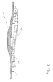
- the abradable system 34 may take a variety of configurations, it may generally comprise a sandwich structure 36 and at least one abradable layer 38, as shown in FIG. 2 .
- sandwich structure refers to a multi-layered structure generally comprising a first facesheet 33, and a second facesheet 33 positioned about at least one core layer 37, as shown in FIG. 2 .
- First and second facesheet 33, as well as core layer 37, may comprise any woven, braided, or non-crimp fabric capable of being infused with a resin and cured to produce a composite material, such as carbon fibers, graphite fibers, glass fibers, ceramic fibers, and aramid polymer fiber.
- the material used in core layer 37 can have non-isotropic properties, and may include cell, columnar, and truss configurations.
- a plurality of core layers 37 may be desirable to permit tailoring of the orthotropic properties of sandwich structure 36 as a function of the fan casing radius or thickness.
- sandwich structure 36 can include, but should not be limited to, TYCOR® (WebCore Technologies, Inc., Miamisburg, Ohio, see U.S. Patent Application 2005/0074593 ) shown in FIG. 2 , or 3-D woven truss configurations ( Bally Ribbon Mills, Bally, PA, see U.S. Patents 6,742,547 and 6,892,766 ) shown in FIGS 4 and 5 .
- TYCOR® WebCore Technologies, Inc., Miamisburg, Ohio, see U.S. Patent Application 2005/0074593
- 3-D woven truss configurations Bally Ribbon Mills, Bally, PA, see U.S. Patents 6,742,547 and 6,892,766 ) shown in FIGS 4 and 5 .
- sandwich structure 36 can be designed to be strong radially and weak circumferentially. Radial strength will allow for the absorption and dissipation of impact energy generated by a released fan blade, as well as the alteration of the released blade's flight trajectory. Circumferential weakness will allow for sandwich structure 36 to become crushed and deformed when impacted by a fan blade due to unbalanced rotor orbiting. Taken together, this radial strength and circumferential weakness can allow the sandwich structure 36 to help absorb energy generated by a released fan blade, thereby reducing the energy that will need to be absorbed by the fan casing. This can lead to the fabrication of a thinner, lighter fan casing. Additionally, sandwich structure 36 can maintain its mechanical integrity, thereby reducing the likelihood the released fan blade will contact and/or significantly damage the fan casing.
- Abradable layer 38 refers to the radially innermost layer of integrated abradable system 34 and provides a region against which the fan blades may occasionally rub throughout engine operation.
- Abradable layer 38 may generally comprise any low-density, syntactic film epoxy suitable for use in a clearance control application that can be resistant to damage from ice impact and can be easily repaired/replaced throughout the service life time of the fan casing, as explained herein below.
- a suitable material for use as abradable layer 38 is Hysol® EA 9890, though the embodiments herein should not be limited to such.
- abradable layer 38 can be bonded to the fan casing so as to cover sandwich structure 36. Any conventional bonding materials and techniques known to those skilled in the art may are acceptable for use herein.
- a fan casing having an integrated abradable system 35 can be made using conventional composite manufacturing processes. However, some modifications to the tooling used in the process are required.
- a mandrel 40 may be provided for fabricating embodiments of the fan casing described herein. Mandrel 40 may be similar to conventional tools used in fan casing fabrication, see for example, U.S. Patent Application No. 2006/0134251 to Blanton et al ., with the exception that mandrel 40 can have a pocket 42 disposed circumferentially thereabout for receiving truss core layer 36 of abradable system 34. Mandrel 40 can be "substantially cylindrical,” and may be generally shaped like a cylinder, either with or without a contour.
- pocket 42 may have any dimension that corresponds to the desired dimensions of sandwich structure 36 of abradable system 34.
- pocket 42 (and therefore sandwich structure 36) can have a width W of from about one to about three times the axial chord length L of fan blade 18 as indicated in FIG. 1 , and a depth D of from about one to about five times the radial thickness T of fan casing. "radial thickness" is measured at the thickest cross-section of the fan casing, as shown in FIG. 5 .
- pocket 42 may have a width W of from about 12 inches (about 30.4 cm) to about 36 inches (about 91.4 cm) and a depth D of from about 1 inch (about 2.54 cm) to about 5 inches (about 12.7 cm).
- abradable system 34 functions to absorb impact from a released fan blade, pocket 42 can be positioned along mandrel 40 such that sandwich structure 36, and therefore abradable system 34, will be adjacent to fan blades 18 when the fan assembly of the engine is assembled, as shown in FIG. 5 .
- sandwich structure 36 having the desired number of core layers 37 may first be positioned within pocket 42 of mandrel 40, as shown in FIG. 4 .
- at least one ply of a material 44 may be continuously applied about mandrel 40 having pocket 42 containing sandwich structure 36 until the desired thickness is obtained.
- material 44 may comprise any woven, braided, or non-crimp fabric capable of being infused with a resin and cured to produce a composite material.
- the material may comprise carbon fibers, graphite fibers, glass fibers, ceramic fibers, and aramid polymer fibers. Additionally, each fiber tow may comprise from about 3000 to about 24,000 individual fiber filaments.
- the resulting fan casing preform 46 having an integrated sandwich structure 36 may be treated with any suitable resin, such as epoxy, using conventional techniques for infusing the resin throughout the fan casing preform 46 and the integrated sandwich structure 36. Once the resin has been infused, fan casing preform 46 may then be cured using traditional curing methods known to those skilled in the art.
- any suitable resin such as epoxy
- fan casing preform 46 can be layed up about a conventional mandrel using conventional techniques, followed by resin infusion and curing.
- the resulting fan casing may then have sandwich structure 36, which has been previously resin-infused and cured, bonded to interior 19 thereof.
- sandwich structure 36 can be positioned adjacent to fan blades 18 when the fan assembly of the engine is assembled, as shown in FIG. 5 .
- At least one abradable layer 38 may be applied over sandwich structure 36, as shown in FIG. 5 , using any suitable method, including, but not limited to, adhesively bonding or mechanically attaching. Further finishing steps conventional to all fan casing fabrication processes, such as the application of one or more acoustic panels 48, may then be carried out.
- the integrated abradable systems of the fan casing embodiment described herein can provide several benefits in addition to those previously discussed.
- the fan casing embodiments herein can require significantly fewer layup, bonding, cure, and machining cycles than conventional fan casings due to the integrated nature and construction of the abradable system.
- the sandwich structure core layer(s) can be made from any non-metallic, composite materials, the abradable systems herein can better absorb impact energy, yet still be lightweight.
- the embodiments of abradable system described herein can absorb up to about 25% of the impact energy generated by a released fan blade, leaving only about 75% of the impact energy to be absorbed by the body of the fan casing.
- impact energy it is meant the kinetic energy of the released fan blade. This allows the thickness and, therefore, the weight, of fan casing 35 to be reduced.
- repair Another benefit provided by the presently described embodiments is ease of repair.
- the entire abradable system need not be removed and reapplied if the damage is limited to only a portion thereof. Rather, should a portion of the abradable system become damaged by ice shedding, a fan blade out, or other like occurrence, that portion only can be replaced. Similar to fabrication, repair may be carried out in a couple of ways. In one embodiment, the damaged portion of the abradable system can be machined, or cut, out of the fan casing using conventional methods leaving a hole in the abradable system.
- a sandwich structure segment which can comprise any number of core layers and facesheets as needed, may then be shaped to the proper dimensions need to fill the hole and to create a shaped sandwich structure.
- the shaped sandwich structure may then be positioned within the hole in the abradable system and resin may be infused therein.
- the fan casing having the shaped sandwich structure may then be cured to produce a fan casing having a repaired integrated abradable system.
- the damaged portion of the abradable system can again be machined out using conventional methods to create a hole in the abradable system.
- a sandwich structure segment may be shaped to the proper dimensions need to fill the hole in the abradable system and to create a shaped sandwich structure.
- the shaped sandwich structure may first be infused with resin and cured before being placed into hole and bonded to the abradable system to produce a fan casing having a repaired integrated abradable system.
- any acceptable adhesive or other like material may be used to bond the shaped sandwich structure in the hole on the abradable system.
- a new abradable layer may be applied to the filler sandwich structure in the manner described previously.
- the repaired fan casing having the integrated abradable system can provide all of the benefits described previously.
- the ability to repair only the damaged portion of the fan casing can reduce the time and expense that would otherwise be involved in replacing the entire abradable system.
Landscapes
- Engineering & Computer Science (AREA)
- Mechanical Engineering (AREA)
- Chemical & Material Sciences (AREA)
- Composite Materials (AREA)
- General Engineering & Computer Science (AREA)
- Combustion & Propulsion (AREA)
- Structures Of Non-Positive Displacement Pumps (AREA)
- Casting Or Compression Moulding Of Plastics Or The Like (AREA)
Applications Claiming Priority (1)
| Application Number | Priority Date | Filing Date | Title |
|---|---|---|---|
| US11/954,844 US8046915B2 (en) | 2007-12-12 | 2007-12-12 | Methods for making composite containment casings |
Publications (2)
| Publication Number | Publication Date |
|---|---|
| EP2070689A2 true EP2070689A2 (fr) | 2009-06-17 |
| EP2070689A3 EP2070689A3 (fr) | 2017-07-26 |
Family
ID=40509991
Family Applications (1)
| Application Number | Title | Priority Date | Filing Date |
|---|---|---|---|
| EP08170608.7A Withdrawn EP2070689A3 (fr) | 2007-12-12 | 2008-12-03 | Procédés de fabrication de boîtiers de confinement composite |
Country Status (4)
| Country | Link |
|---|---|
| US (1) | US8046915B2 (fr) |
| EP (1) | EP2070689A3 (fr) |
| JP (1) | JP5253987B2 (fr) |
| CA (1) | CA2645377C (fr) |
Cited By (9)
| Publication number | Priority date | Publication date | Assignee | Title |
|---|---|---|---|---|
| WO2012018919A1 (fr) * | 2010-08-04 | 2012-02-09 | General Electric Company | Système de confinement de carter de ventilateur et procédé de fabrication |
| WO2012112366A1 (fr) * | 2011-02-15 | 2012-08-23 | Siemens Energy, Inc. | Mesure de la distance pour des extrémités de pales de turbine |
| WO2013122635A3 (fr) * | 2011-12-15 | 2013-11-14 | General Electric Company | Enceinte de confinement et procédé de fabrication |
| WO2014046827A1 (fr) * | 2012-09-21 | 2014-03-27 | General Electric Company | Procédé et système de fabrication de carcasses de confinement composites |
| EP2940251A1 (fr) * | 2014-04-28 | 2015-11-04 | Rolls-Royce Corporation | Carter de confinement de soufflante |
| FR3037854A1 (fr) * | 2015-06-29 | 2016-12-30 | Snecma | Procede de fabrication d'un carter de soufflante en materiau composite a panneau abradable integre pour moteur a turbine a gaz et carter ainsi obtenu |
| FR3074088A1 (fr) * | 2017-11-30 | 2019-05-31 | Safran Aircraft Engines | Carter en materiau composite renforce et son procede de fabrication |
| WO2020011618A1 (fr) * | 2018-07-13 | 2020-01-16 | Rolls-Royce Plc | Revêtement de piste de ventilateur |
| US12359572B2 (en) | 2023-02-20 | 2025-07-15 | General Electric Company | Turbine engine with composite airfoils |
Families Citing this family (22)
| Publication number | Priority date | Publication date | Assignee | Title |
|---|---|---|---|---|
| US8586179B1 (en) * | 2010-04-09 | 2013-11-19 | The Boeing Company | Mechanical attachment for micro-truss actively cooled structural insulation layer |
| US9644493B2 (en) * | 2012-09-07 | 2017-05-09 | United Technologies Corporation | Fan case ballistic liner and method of manufacturing same |
| FR3007064B1 (fr) * | 2013-06-13 | 2018-06-29 | Composite Industrie | Secteur de joint annulaire abradable pour turbomachine et procede de fabrication d'une telle piece |
| FR3007063B1 (fr) | 2013-06-13 | 2015-07-03 | Composite Ind | Piece de materiau abradable pour la fabrication d'un secteur de joint annulaire abradable pour turbomachine et procede de fabrication d'une telle piece |
| US10378554B2 (en) * | 2014-09-23 | 2019-08-13 | Pratt & Whitney Canada Corp. | Gas turbine engine with partial inlet vane |
| US10145301B2 (en) | 2014-09-23 | 2018-12-04 | Pratt & Whitney Canada Corp. | Gas turbine engine inlet |
| US9957807B2 (en) | 2015-04-23 | 2018-05-01 | Pratt & Whitney Canada Corp. | Rotor assembly with scoop |
| US9938848B2 (en) | 2015-04-23 | 2018-04-10 | Pratt & Whitney Canada Corp. | Rotor assembly with wear member |
| US10125788B2 (en) | 2016-01-08 | 2018-11-13 | General Electric Company | Ceramic tile fan blade containment |
| US10907651B2 (en) | 2016-01-12 | 2021-02-02 | Rolls-Royce Corporation | Fan track liner subassembly angled upturn joint |
| US10519965B2 (en) | 2016-01-15 | 2019-12-31 | General Electric Company | Method and system for fiber reinforced composite panels |
| US10677264B2 (en) | 2016-10-14 | 2020-06-09 | General Electric Company | Supersonic single-stage turbofan engine |
| US10724540B2 (en) | 2016-12-06 | 2020-07-28 | Pratt & Whitney Canada Corp. | Stator for a gas turbine engine fan |
| US10690146B2 (en) | 2017-01-05 | 2020-06-23 | Pratt & Whitney Canada Corp. | Turbofan nacelle assembly with flow disruptor |
| US10487684B2 (en) | 2017-03-31 | 2019-11-26 | The Boeing Company | Gas turbine engine fan blade containment systems |
| US10550718B2 (en) | 2017-03-31 | 2020-02-04 | The Boeing Company | Gas turbine engine fan blade containment systems |
| US10711635B2 (en) * | 2017-11-07 | 2020-07-14 | General Electric Company | Fan casing with annular shell |
| CN111542435B (zh) * | 2017-12-06 | 2022-06-17 | 赛峰航空器发动机 | 用于在涡轮发动机壳体上原位增材制造涂层的方法 |
| WO2019110939A1 (fr) * | 2017-12-06 | 2019-06-13 | Safran Aircraft Engines | Procédé de fabrication d'un réseau ordonne de canaux acoustiques en matériau abradable |
| US10808565B2 (en) * | 2018-05-22 | 2020-10-20 | Rolls-Royce Plc | Tapered abradable coatings |
| CN114055805B (zh) * | 2020-08-10 | 2023-09-08 | 中国航发商用航空发动机有限责任公司 | 航空发动机风扇易磨环的制造方法 |
| US20230193827A1 (en) * | 2021-12-21 | 2023-06-22 | Rolls-Royce Deutschland Ltd & Co Kg | Fan case assembly for a gas turbine engine |
Citations (4)
| Publication number | Priority date | Publication date | Assignee | Title |
|---|---|---|---|---|
| US5344280A (en) | 1993-05-05 | 1994-09-06 | General Electric Company | Impact resistant fan case liner |
| US6742547B2 (en) | 2000-09-20 | 2004-06-01 | Bally Ribbon Mills | Three-dimensional woven forms with integral bias fibers and bias weaving loom |
| US20050074593A1 (en) | 2000-12-27 | 2005-04-07 | Webcore Technologies, Inc. | Fiber reinforced composite cores and panels |
| US20060134251A1 (en) | 2004-12-22 | 2006-06-22 | General Electric Company | Apparatus for fabricating reinforced composite materials |
Family Cites Families (26)
| Publication number | Priority date | Publication date | Assignee | Title |
|---|---|---|---|---|
| FR2347858A5 (fr) * | 1973-07-06 | 1977-11-04 | Snecma | Tambour pour rotor de compresseur et son procede de fabrication |
| US4149824A (en) * | 1976-12-23 | 1979-04-17 | General Electric Company | Blade containment device |
| FR2467978A1 (fr) * | 1979-10-23 | 1981-04-30 | Snecma | Dispositif de retention pour carter de compresseur d'une turbomachine |
| DE3830232A1 (de) * | 1988-09-06 | 1990-03-15 | Mtu Muenchen Gmbh | Berstschutzring aus faserwerkstoff |
| US5160248A (en) * | 1991-02-25 | 1992-11-03 | General Electric Company | Fan case liner for a gas turbine engine with improved foreign body impact resistance |
| AU7470394A (en) * | 1993-05-04 | 1995-02-20 | Foster-Miller Inc. | Truss reinforced foam core sandwich structure |
| US5451448A (en) * | 1993-07-01 | 1995-09-19 | The United States Of America As Represented By The United States National Aeronautics And Space Administration | Flexible ceramic thermal protection system resistant to high aeroacoustic noise comprising a three-dimensional woven-fiber structure having a multilayer top fabric layer, a bottom fabric layer and an intermediate rib fabric layer |
| US5486086A (en) * | 1994-01-04 | 1996-01-23 | General Electric Company | Blade containment system |
| US5516257A (en) * | 1994-04-28 | 1996-05-14 | United Technologies Corporation | Aircraft fan containment structure restraint |
| US5431532A (en) * | 1994-05-20 | 1995-07-11 | General Electric Company | Blade containment system |
| AU1822997A (en) * | 1996-01-11 | 1997-08-01 | Boeing Company, The | Composite honeycomb sandwich structure |
| US6059524A (en) * | 1998-04-20 | 2000-05-09 | United Technologies Corporation | Penetration resistant fan casing for a turbine engine |
| CA2347717A1 (fr) * | 1998-09-30 | 2000-04-06 | Toray Industries, Inc. | Structure creuse en resine renforcee par des fibres et son procede de fabrication |
| US6510961B1 (en) * | 1999-04-14 | 2003-01-28 | A&P Technology | Integrally-reinforced braided tubular structure and method of producing the same |
| US6290455B1 (en) * | 1999-12-03 | 2001-09-18 | General Electric Company | Contoured hardwall containment |
| ES2573671T3 (es) * | 1999-12-28 | 2016-06-09 | Milliken & Company | Núcleos de material compuesto reforzados con fibras |
| US6814541B2 (en) * | 2002-10-07 | 2004-11-09 | General Electric Company | Jet aircraft fan case containment design |
| US20050003172A1 (en) * | 2002-12-17 | 2005-01-06 | General Electric Company | 7FAstage 1 abradable coatings and method for making same |
| GB0300999D0 (en) * | 2003-01-16 | 2003-02-19 | Rolls Royce Plc | A gas turbine engine blade containment assembly |
| FR2854198B1 (fr) * | 2003-04-22 | 2005-06-24 | Snecma Services | Procede pour remplacer un abradable sur le carter de soufflante d'un turboreacteur |
| GB0408825D0 (en) * | 2004-04-20 | 2004-05-26 | Rolls Royce Plc | A rotor blade containment assembly for a gas turbine engine |
| GB2416192B (en) * | 2004-07-14 | 2006-09-27 | Rolls Royce Plc | Ducted fan with containment structure |
| JP4180554B2 (ja) * | 2004-10-06 | 2008-11-12 | 天龍工業株式会社 | 中空材を構成する中空材本体の製造方法 |
| US7246990B2 (en) * | 2004-12-23 | 2007-07-24 | General Electric Company | Composite fan containment case for turbine engines |
| GB2426287B (en) * | 2005-05-18 | 2007-05-30 | Rolls Royce Plc | Blade containment structure |
| US20080081109A1 (en) * | 2006-09-29 | 2008-04-03 | General Electric Company | Porous abradable coating and method for applying the same |
-
2007
- 2007-12-12 US US11/954,844 patent/US8046915B2/en active Active
-
2008
- 2008-11-27 CA CA2645377A patent/CA2645377C/fr not_active Expired - Fee Related
- 2008-12-03 EP EP08170608.7A patent/EP2070689A3/fr not_active Withdrawn
- 2008-12-10 JP JP2008313982A patent/JP5253987B2/ja not_active Expired - Fee Related
Patent Citations (5)
| Publication number | Priority date | Publication date | Assignee | Title |
|---|---|---|---|---|
| US5344280A (en) | 1993-05-05 | 1994-09-06 | General Electric Company | Impact resistant fan case liner |
| US6742547B2 (en) | 2000-09-20 | 2004-06-01 | Bally Ribbon Mills | Three-dimensional woven forms with integral bias fibers and bias weaving loom |
| US6892766B2 (en) | 2000-09-20 | 2005-05-17 | Bally Ribbon Mills | Loom and method of weaving three-dimensional woven forms with integral bias fibers |
| US20050074593A1 (en) | 2000-12-27 | 2005-04-07 | Webcore Technologies, Inc. | Fiber reinforced composite cores and panels |
| US20060134251A1 (en) | 2004-12-22 | 2006-06-22 | General Electric Company | Apparatus for fabricating reinforced composite materials |
Cited By (18)
| Publication number | Priority date | Publication date | Assignee | Title |
|---|---|---|---|---|
| US8986797B2 (en) | 2010-08-04 | 2015-03-24 | General Electric Company | Fan case containment system and method of fabrication |
| WO2012018919A1 (fr) * | 2010-08-04 | 2012-02-09 | General Electric Company | Système de confinement de carter de ventilateur et procédé de fabrication |
| WO2012112366A1 (fr) * | 2011-02-15 | 2012-08-23 | Siemens Energy, Inc. | Mesure de la distance pour des extrémités de pales de turbine |
| US8684669B2 (en) | 2011-02-15 | 2014-04-01 | Siemens Energy, Inc. | Turbine tip clearance measurement |
| WO2013122635A3 (fr) * | 2011-12-15 | 2013-11-14 | General Electric Company | Enceinte de confinement et procédé de fabrication |
| US9248612B2 (en) | 2011-12-15 | 2016-02-02 | General Electric Company | Containment case and method of manufacture |
| WO2014046827A1 (fr) * | 2012-09-21 | 2014-03-27 | General Electric Company | Procédé et système de fabrication de carcasses de confinement composites |
| US9828876B2 (en) | 2014-04-28 | 2017-11-28 | Rolls-Royce Corporation | Fan containment case |
| EP2940251A1 (fr) * | 2014-04-28 | 2015-11-04 | Rolls-Royce Corporation | Carter de confinement de soufflante |
| FR3037854A1 (fr) * | 2015-06-29 | 2016-12-30 | Snecma | Procede de fabrication d'un carter de soufflante en materiau composite a panneau abradable integre pour moteur a turbine a gaz et carter ainsi obtenu |
| FR3074088A1 (fr) * | 2017-11-30 | 2019-05-31 | Safran Aircraft Engines | Carter en materiau composite renforce et son procede de fabrication |
| US11491743B2 (en) | 2017-11-30 | 2022-11-08 | Safran Aircraft Engines | Casing of reinforced composite material, and a method of fabricating it |
| WO2020011618A1 (fr) * | 2018-07-13 | 2020-01-16 | Rolls-Royce Plc | Revêtement de piste de ventilateur |
| CN112424450A (zh) * | 2018-07-13 | 2021-02-26 | 劳斯莱斯股份有限公司 | 风扇轨道衬里 |
| US11448090B2 (en) | 2018-07-13 | 2022-09-20 | Rolls-Royce Plc | Fan track liner |
| EP4105452A1 (fr) * | 2018-07-13 | 2022-12-21 | Rolls-Royce plc | Chemisage pour voie de soufflante |
| US11746673B2 (en) | 2018-07-13 | 2023-09-05 | Rolls-Royce Plc | Manufacture of a fan track liner |
| US12359572B2 (en) | 2023-02-20 | 2025-07-15 | General Electric Company | Turbine engine with composite airfoils |
Also Published As
| Publication number | Publication date |
|---|---|
| JP2009143230A (ja) | 2009-07-02 |
| EP2070689A3 (fr) | 2017-07-26 |
| JP5253987B2 (ja) | 2013-07-31 |
| US20090152764A1 (en) | 2009-06-18 |
| US8046915B2 (en) | 2011-11-01 |
| CA2645377A1 (fr) | 2009-06-12 |
| CA2645377C (fr) | 2016-07-05 |
Similar Documents
| Publication | Publication Date | Title |
|---|---|---|
| US8046915B2 (en) | Methods for making composite containment casings | |
| US8061966B2 (en) | Composite containment casings | |
| US8403624B2 (en) | Composite containment casings having an integral fragment catcher | |
| US8371009B2 (en) | Methods for repairing composite containment casings | |
| EP2815084B1 (fr) | Boîtier de turbine à gaz avec chemisage balistique | |
| US11448090B2 (en) | Fan track liner | |
| WO2008130738A1 (fr) | Procédés permettant de fabriquer des articles présentant des régions durcies et non durcies | |
| US12123324B2 (en) | Engine airfoil metal edge | |
| US11149584B2 (en) | Containment case having ceramic coated fibers | |
| US20090151162A1 (en) | Methods for making composite containment casings having an integral fragment catcher | |
| EP3249163B1 (fr) | Système et procédé de réparation de délaminage de bord de cône de nez | |
| CN115217627A (zh) | 燃气涡轮发动机的翼型件 | |
| US11506083B2 (en) | Composite liners for turbofan engines | |
| US11549391B2 (en) | Component formed from hybrid material |
Legal Events
| Date | Code | Title | Description |
|---|---|---|---|
| PUAI | Public reference made under article 153(3) epc to a published international application that has entered the european phase |
Free format text: ORIGINAL CODE: 0009012 |
|
| AK | Designated contracting states |
Kind code of ref document: A2 Designated state(s): AT BE BG CH CY CZ DE DK EE ES FI FR GB GR HR HU IE IS IT LI LT LU LV MC MT NL NO PL PT RO SE SI SK TR |
|
| AX | Request for extension of the european patent |
Extension state: AL BA MK RS |
|
| PUAL | Search report despatched |
Free format text: ORIGINAL CODE: 0009013 |
|
| AK | Designated contracting states |
Kind code of ref document: A3 Designated state(s): AT BE BG CH CY CZ DE DK EE ES FI FR GB GR HR HU IE IS IT LI LT LU LV MC MT NL NO PL PT RO SE SI SK TR |
|
| AX | Request for extension of the european patent |
Extension state: AL BA MK RS |
|
| RIC1 | Information provided on ipc code assigned before grant |
Ipc: B29C 70/44 20060101ALI20170616BHEP Ipc: B29C 70/08 20060101ALI20170616BHEP Ipc: F01D 11/12 20060101ALI20170616BHEP Ipc: B29C 70/48 20060101AFI20170616BHEP |
|
| REG | Reference to a national code |
Ref country code: DE Ref legal event code: R108 |
|
| AKY | No designation fees paid | ||
| AXX | Extension fees paid |
Extension state: RS Extension state: MK Extension state: AL Extension state: BA |
|
| STAA | Information on the status of an ep patent application or granted ep patent |
Free format text: STATUS: THE APPLICATION IS DEEMED TO BE WITHDRAWN |
|
| 18D | Application deemed to be withdrawn |
Effective date: 20180127 |