EP2070764A2 - Structure de rétention de ressort de coussin - Google Patents
Structure de rétention de ressort de coussin Download PDFInfo
- Publication number
- EP2070764A2 EP2070764A2 EP08253721A EP08253721A EP2070764A2 EP 2070764 A2 EP2070764 A2 EP 2070764A2 EP 08253721 A EP08253721 A EP 08253721A EP 08253721 A EP08253721 A EP 08253721A EP 2070764 A2 EP2070764 A2 EP 2070764A2
- Authority
- EP
- European Patent Office
- Prior art keywords
- claw
- frame
- cushion
- pair
- supporting members
- Prior art date
- Legal status (The legal status is an assumption and is not a legal conclusion. Google has not performed a legal analysis and makes no representation as to the accuracy of the status listed.)
- Granted
Links
Images


Classifications
-
- B—PERFORMING OPERATIONS; TRANSPORTING
- B60—VEHICLES IN GENERAL
- B60N—SEATS SPECIALLY ADAPTED FOR VEHICLES; VEHICLE PASSENGER ACCOMMODATION NOT OTHERWISE PROVIDED FOR
- B60N2/00—Seats specially adapted for vehicles; Arrangement or mounting of seats in vehicles
- B60N2/70—Upholstery springs ; Upholstery
- B60N2/72—Attachment or adjustment thereof
-
- B—PERFORMING OPERATIONS; TRANSPORTING
- B60—VEHICLES IN GENERAL
- B60N—SEATS SPECIALLY ADAPTED FOR VEHICLES; VEHICLE PASSENGER ACCOMMODATION NOT OTHERWISE PROVIDED FOR
- B60N2/00—Seats specially adapted for vehicles; Arrangement or mounting of seats in vehicles
- B60N2/70—Upholstery springs ; Upholstery
- B60N2/7094—Upholstery springs
Definitions
- the present invention relates to a retaining structure for a cushion spring in a frame of a vehicle seat.
- a kind of cushion spring retaining structure wherein a cushion spring is stretched over a frame of a seat cushion is described in JP-A-2001-120383 .
- This retaining structure includes a hook formed by bending one end of the cushion spring (in a bridging form in a seat width direction), and a claw formed protruding from an upper surface of the frame at a front side.
- the claw is a plate member (of an approximate L shape when viewed side on) including an upright segment, standing perpendicular to the upper surface of the frame, and an extended segment at an upper portion thereof extending toward a seat front side.
- the claw inevitably protrudes on a padding member side from the cushion spring in the stretched condition.
- the padding member comes into contact with the protruding claw (the extended segment), and is capable of being damaged (a so-called padding cutting occurs).
- the installation is more difficult because the supporting stand need be installed on the frame before a cushion spring retaining operation.
- the present invention can include a seat frame including a claw member, a spring member having a first end and a second end both connected to the frame, wherein the first end is retainable in the claw member, also the first end includes a first and second support member positioned on either side of the claw member, the first and second support member having a height that is equal to or greater than a height of the claw member.
- a reference letter F will be given to a front side of a vehicle seat, and a reference letter B to a back side of the vehicle seat.
- a vehicle seat 2 of a first embodiment includes a seat cushion 4 and a seat back 6.
- the seat cushion 4 is configured by stretching cushion springs 30 (a first cushion spring 30A to a fourth cushion spring 30D, to be described hereafter) over a frame 10, which forms a seat skeleton.
- the seat cushion 4 is configured by disposing a padding member 4P on the four cushion springs. Then, the embodiment, taking the frame 10 of the seat cushion 4 as an example, will describe a retaining structure of the cushion springs 30 (30A to 30D).
- the frame 10 of the seat cushion 4, referring to Fig. 1 has an anterior frame 12, which configures an anterior skeleton, and a pair of lateral frames 14 and 14, which configure a lateral skeleton. Then, a pipe frame 16 is disposed in a bridging form on the pair of lateral frames 14 and 14, on a seat back side B thereof. Further, the anterior frame 12 of the embodiment can have a rectangular member horizontally long (when viewed from above), the seat back side B can be inclined in a downward direction (refer to Fig. 2 ).
- the anterior frame 12 includes claws 20, capable of retaining the cushion springs 30A to 30D, and are formed protruding on an upper surface (an inclining surface).
- the claw 20 of the embodiment forms an approximate L shape when viewed from the side.
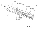
- the claw 20 includes an upright portion 22 and extended portion 24. This can be formed by cutting and raising one portion, of a width dimension of W1, of the upper surface of the anterior frame 12, and the extended portion 24 formed by bending an upper side of the upright portion 22 towards a seat front side F. Then, in the embodiment, referring to Fig. 4 , a projection height dimension of the claw 20 with respect to the upper surface of the anterior frame 12 (a dimension of a height from the upper surface of the anterior frame 12 to the extended portion 24) is set at T1. Also, in this embodiment (corresponding to the number of cushion springs) claws 20 are formed at predetermined intervals in a seat width direction on the anterior frame 12.
- each cushion spring 30A to 30D configured approximately the same.
- a first cushion spring 30A (disposed at a right extremity as seen in Fig. 1 ) is a wire rod of a zigzag configuration that includes section similar to an approximate reverse S shape that are joined together.
- One end of the first cushion spring 30A (a seat front side F extremity) is bent in the seat width direction, and is made a hook 32 which can be retained in the claw 20 (in a bridging form in the seat width direction - a left to right direction as seen in Fig. 1 ).
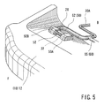
- a retaining structure of the embodiment includes the pair of supporting members (50A and 50B), which support the padding member 4P, and a linking attachment 60, which links and integrates the cushion springs 30A to 30D.
- Each of the pair of supporting members (a first supporting member 50A and a second supporting member 50B), referring to Fig. 2 , can be a resin member (typically made of a resin such as a polyethylene resin or a polypropylene resin) of an approximately semi-circular form when viewed from the side.
- a length dimension of the first supporting member 50A is set to be slightly larger (longer) than the second supporting member 50B.
- a height (thickness) dimension T2 from a bottom surface to a semi-circular side apex thereof is set to be higher than the heretofore described claw 20 protrusion height dimension T1.
- each of the pair of supporting members 50A and 50B is installed on the hook 32 in a positional disposition in which its bottom surface side faces the anterior frame 12. That is, the pairs of supporting members 50A and 50B are installed, at predetermined intervals in the seat width direction, on the hook 32 of each of the cushion springs 30A to 30D.
- the pairs of supporting members 50A and 50B make contact with the padding member 4P with their semi-circular shaped sides (here, a comerless shape).
- the hook 32 takes on an approximate reverse J shape when viewed head on, and it is possible to securely retain each cushion spring 30A to 30D in the claws 20.
- a separation dimension W2 of the pair of supporting members 50A and 50B is set to be almost identical to the claw 20 width dimension W1 (a zero gap setting). Then, at a time, to be described hereafter, of retaining the cushion springs 30A to 30D, the hook 32 exposed between the pair of supporting members 50A and 50B is caused to curve, widening a gap between the pair of supporting members 50A and 50B. Then, while widening the gap between the pair of supporting members 50A and 50B, the hook 32 is fitted into the claw 20 and retained. Then, after the retaining, the hook 32 (between the pair of supporting members 50A and 50B) takes on its original straight form, and the claw 20 is gripped by the pair of supporting members 50A and 50B disposed one on either side of the claw 20.
- the linking attachment 60 can be a resin member which links the cushion springs 30A to 30D, maintaining a predetermined disposition condition.
- the first cushion spring 30A and the second cushion spring 30B are made into one pair, and disposed on a right side.
- the third cushion spring 30C and the fourth cushion spring 30D are made into another pair, and disposed on a left side.
- the one pair and the other pair are disposed in the frame 10 in such a way as to be bilaterally symmetrical when viewed from above.
- the hook 32 of the first cushion spring 30A and the hook 32 of the second cushion spring 30B are positioned into a mutually facing form, and their second straight portions 38 are disposed in close proximity to each other.
- a configuration is such that the hook 32 of the third cushion spring 30C and the hook 32 of the fourth cushion spring 30D are positioned into a mutually facing form, and their second straight portions 38 are disposed in close proximity to each other.
- the hooks 32 of the second cushion spring 30B and the third cushion spring 30C are positioned adjacent to each other, their hooks 32 face in directions opposite to each other.
- a configuration is such that the first straight portion 34 of the second cushion spring 30B and the first straight portion 34 of the third cushion spring 30C are disposed in close proximity to each other.
- the linking attachment 60 includes a cover 62, which covers the first bent portion 36 of the cushion springs 30A to 30D, and linking portions (a first linking portion 64, a second linking portion 65, and a third linking portion 66), which link the cushion springs 30A to 30D.
- the linking attachment 60 of the embodiment is configured as an integrated molded article in which the cover 62 and the linking portions (64, 65 and 66) are joined together.
- the first linking portion 64 is a segment which links the first straight portion 34 of the second cushion spring 30B and the first straight portion 34 of the third cushion spring 30C (segments of both springs which are in close proximity) in a bridging form.
- the second linking portion 65 is a segment which links the second straight portion 38 of the first cushion spring 30A and the second straight portion 38 of the second cushion spring 30B (segments of both springs which are in close proximity) in a bridging form.
- the third linking portion 66 is a segment which links the second straight portion 38 of the third cushion spring 30C and the second straight portion 38 of the fourth cushion spring 30D (segments of both springs which are in close proximity) in a bridging form.
- the cushion springs 30A to 30D are integrally linked by the linking portions (64, 65 and 66), maintaining the disposition condition. By so doing, it is possible to simultaneously carry out retaining operations, to be described hereafter, for the cushion springs 30A to 30D.
- one portion thereof (primarily the hook 32, the first straight portion 34, and the first bent portion 36, on the one extremity side) are disposed in such a way as to ride up on the anterior frame 12.
- a strange noise for example, a metallic noise
- a configuration is such that the one portion of each of the cushion springs 30A to 30D is supported by a resin member.
- the hook 32 is supported by the supporting members (50A and 50B).
- the first bent portion 36 joined to the first straight portion 34 is supported by covering it with the linking attachment 60 (the cover 62).
- the cushion springs 30A to 30D linked by the linking attachment 60 are latched onto the pipe frame 16, from a seat up-down direction, using the latching attachment 40 provided at the other end of each of them. Then, retaining the hook 32 of each of the cushion springs 30A to 30D in the claws 20 (in a bridging form in the seat width direction - the left to right direction), the cushion springs 30A to 30D are stretched over the frame 10. Then, referring to Fig. 4 , the padding member 4P of the seat front side F (one side of the vehicle seat) is supported by the pair of supporting members 50A and 50B disposed one on either side of the claw 20.
- the padding member 4P is supported by the pair of supporting members 50A and 50B of the dimension T2, which is higher than the protrusion dimension T1 of the claw 20.
- the hook 32 exposed between the pair of supporting members 50A and 50B is of a configuration wherein it is covered with a resin covering member 52. Then, the covering member 52 is provided in a bridging form on the pair of supporting members 50A and 50B.
- the covering member 52 and the pair of supporting members 50A and 50B are typically configured as an integrated molded article. According to this embodiment, a whole of the hook 32 exposed between the pair of supporting members 50A and 50B is covered by the covering member 52.
- the cushion spring retaining structure of the embodiment is not limited to the previously described embodiments, and therefore it is possible to adopt various other embodiments.
- the claw 20 is described as having an approximate L shape when viewed side on, it is also acceptable that the claw 20 can be of any kind of shape, as long as it can retain the hook 32.
- the claw can adopt various kinds of shape such as, for example, a horizontal U shape, a Z shape, a C shape, or an E shape, when viewed side on.
- the claw is of a simple configuration wherein a rod member or a plate member is erected on the frame 10.
- the claw 20 is also described as being configured by cutting and raising one portion of the upper surface of the anterior frame 12 (an example reducing a number of parts). Differing from this, it is also acceptable to use a claw which is a member separate from the anterior frame 12.
- the supporting members (50A and 50B) can have an approximately semi-circular shape when viewed from the side. It is also acceptable that the supporting members (50A and 50B) are of any kind of shape, as long as they can support the padding member 4P without, as far as possible, reducing or eliminating damage it.
- the shape of the supporting members (50A and 50B) is a comerless shape, like a semi-circular shape, a semi-elliptical shape, an elliptical shape or a circular shape, when viewed side on, or a multiangular shape in which corners are rounded, such as a radiused triangle or a radiused quadrilateral.
- the height (thickness) dimension T2 of the pair of supporting members 50A and 50B is set to be higher than the claw 20 protrusion height dimension T1. Differing from this, it is also acceptable to set the height (thickness) dimension T2 of the pair of supporting members 50A and 50B and the claw 20 protrusion height dimension T1 to be identical. With this configuration too, by means of the pair of supporting members 50A and 50B supporting the padding member 4P along with the claw 20, it is possible to avoid, as far as possible, the protrusion of the claw 20 on the padding member 4P side.
- the four cushion springs 30A to 30D are stretched on. It is also acceptable to have one or a plurality of cushion springs, and this can be changed appropriately in accordance with a cushioning performance of the frame 10. As previously described, a separate body has been used for each of the cushion springs 30A to 30D. Differing from this, it is also acceptable that the cushion spring is configured by, after bending a single wire rod into, for example, an approximate U shape, making each free end into a zigzag shape. Also, in the embodiment, a description has been given of the example wherein one portion of the cushion spring is made the hook 32, but it is also acceptable to use a hook of a separate member differing from the cushion spring.
- the present invention can be suitably employed in a frame in which it is necessary to retain a cushion spring.
- a cushion spring for example, when attaching a cushion spring to a frame of the seat back 6 too, it is possible to employ the retaining structure of the embodiment.
Landscapes
- Engineering & Computer Science (AREA)
- Aviation & Aerospace Engineering (AREA)
- Transportation (AREA)
- Mechanical Engineering (AREA)
- Seats For Vehicles (AREA)
Applications Claiming Priority (1)
| Application Number | Priority Date | Filing Date | Title |
|---|---|---|---|
| JP2007323288A JP5088123B2 (ja) | 2007-12-14 | 2007-12-14 | クッションバネの掛止め構造 |
Publications (3)
| Publication Number | Publication Date |
|---|---|
| EP2070764A2 true EP2070764A2 (fr) | 2009-06-17 |
| EP2070764A3 EP2070764A3 (fr) | 2015-11-25 |
| EP2070764B1 EP2070764B1 (fr) | 2018-10-24 |
Family
ID=40451298
Family Applications (1)
| Application Number | Title | Priority Date | Filing Date |
|---|---|---|---|
| EP08253721.8A Active EP2070764B1 (fr) | 2007-12-14 | 2008-11-13 | Structure de rétention de ressort de coussin |
Country Status (4)
| Country | Link |
|---|---|
| US (1) | US7794021B2 (fr) |
| EP (1) | EP2070764B1 (fr) |
| JP (1) | JP5088123B2 (fr) |
| CN (1) | CN101456366B (fr) |
Cited By (1)
| Publication number | Priority date | Publication date | Assignee | Title |
|---|---|---|---|---|
| EP2612794A4 (fr) * | 2011-10-25 | 2015-03-25 | Toyota Motor Co Ltd | Siège de véhicule et ressort de dossier de siège en résine |
Families Citing this family (26)
| Publication number | Priority date | Publication date | Assignee | Title |
|---|---|---|---|---|
| JP4183716B2 (ja) | 2006-03-29 | 2008-11-19 | 住友大阪セメント株式会社 | 光導波路素子 |
| JP5251018B2 (ja) | 2007-07-04 | 2013-07-31 | トヨタ紡織株式会社 | 通気性クッション及びその製造方法 |
| JP5349906B2 (ja) * | 2008-10-29 | 2013-11-20 | トヨタ紡織株式会社 | 車両用シートのクッション構造体 |
| JP5387174B2 (ja) * | 2009-06-30 | 2014-01-15 | トヨタ紡織株式会社 | 車両用シート |
| US8746792B2 (en) * | 2010-11-24 | 2014-06-10 | Ford Global Technologies, Llc | Energy management load limiting vehicle seat member |
| JP5561129B2 (ja) * | 2010-11-30 | 2014-07-30 | トヨタ紡織株式会社 | 車両用シート |
| US9050919B2 (en) * | 2010-12-24 | 2015-06-09 | Honda Motor Co., Ltd. | Vehicle seat cushion |
| DE102011117038A1 (de) * | 2011-10-27 | 2013-05-02 | GM Global Technology Operations LLC | Fahrzeugsitz für ein Kraftfahrzeug |
| US9376043B2 (en) * | 2011-11-14 | 2016-06-28 | Ford Global Technologies, Llc | Cushion pan for a vehicle seat assembly |
| LU91997B1 (en) * | 2012-05-10 | 2013-11-11 | Iee Sarl | Seat suspension mat, especially for vehicle seat |
| DE102012108506B4 (de) * | 2012-09-12 | 2024-03-28 | Adient Us Llc | Kraftfahrzeugschalensitz |
| JP6165670B2 (ja) * | 2014-04-25 | 2017-07-19 | トヨタ紡織株式会社 | 乗物用シートフレームのバネ部材取付け構造 |
| JP5951682B2 (ja) * | 2014-06-02 | 2016-07-13 | 株式会社シンダイ | 乗物シート用緩衝体 |
| DE102014111486B4 (de) * | 2014-08-12 | 2017-05-04 | Faurecia Autositze Gmbh | Sitzwanne für einen Fahrzeugsitz, Sitzteil-Anordnung mit der Sitzwanne und Fahrzeugsitz mit der Sitzteil-Anordnung |
| JP2016084009A (ja) * | 2014-10-24 | 2016-05-19 | トヨタ自動車株式会社 | 車両用シート |
| CN104325910A (zh) * | 2014-10-31 | 2015-02-04 | 重庆长安汽车股份有限公司 | 一种汽车座椅曲簧的装配结构 |
| CN104696440B (zh) * | 2015-03-30 | 2016-09-14 | 上海延锋江森座椅有限公司 | 一种坐椅骨架和钢丝的连接结构 |
| JP2016203950A (ja) * | 2015-04-28 | 2016-12-08 | テイ・エス テック株式会社 | 車両用シート |
| JP6473430B2 (ja) * | 2016-03-31 | 2019-02-20 | テイ・エス テック株式会社 | 乗物用シート |
| CN105857137A (zh) * | 2016-04-13 | 2016-08-17 | 芜湖亚利华汽车部件有限公司 | 汽车坐垫弹簧 |
| US10463153B2 (en) | 2016-06-09 | 2019-11-05 | Steelcase Inc. | Seating arrangement |
| US10029594B2 (en) | 2016-10-13 | 2018-07-24 | Ford Global Technologies, Llc | Seat suspension with maximized downward deflection feature |
| US10202060B2 (en) | 2016-10-20 | 2019-02-12 | Ford Global Technologies, Llc | Seat leveler for transporting cargo |
| JP6404882B2 (ja) * | 2016-10-28 | 2018-10-17 | テイ・エス テック株式会社 | 乗物用シート |
| CN111465528B (zh) * | 2017-12-12 | 2022-08-09 | 丰田纺织株式会社 | 交通工具用座椅 |
| CN215993384U (zh) * | 2021-08-30 | 2022-03-11 | 江苏里高智能家居有限公司 | 一种沙发弹性底座 |
Citations (2)
| Publication number | Priority date | Publication date | Assignee | Title |
|---|---|---|---|---|
| JP2001120383A (ja) | 1999-10-26 | 2001-05-08 | Takashimaya Nippatsu Kogyo Co Ltd | 車両用シートフレーム |
| JP2007323288A (ja) | 2006-05-31 | 2007-12-13 | Sumitomo Mitsui Banking Corp | 仕訳情報作成システム、仕訳情報作成方法及び仕訳情報作成プログラム |
Family Cites Families (51)
| Publication number | Priority date | Publication date | Assignee | Title |
|---|---|---|---|---|
| US2695658A (en) * | 1949-04-19 | 1954-11-30 | American Metal Prod | Spring supporting clip having locking tongue |
| US3649077A (en) * | 1970-04-06 | 1972-03-14 | Hyland C Flint | Seat assembly |
| US3992853A (en) * | 1975-06-09 | 1976-11-23 | Morris Max O | Spring clip |
| US4157173A (en) * | 1977-12-30 | 1979-06-05 | Morley Furniture Spring Corporation | Seat base rail connector and assembly |
| US4181835A (en) | 1978-03-27 | 1980-01-01 | Bowden John W | Gas flow indicator having a magnetic field sensitive switch that _is responsive to the position of a magnet secured to a piston |
| US4213021A (en) | 1979-01-19 | 1980-07-15 | Aeroquip Corporation | Indicating check valve |
| EP0036759B1 (fr) | 1980-03-21 | 1984-06-13 | Alan Cobham Engineering Limited | Mécanisme d'opération d'un interrupteur répondant à la pression |
| US4357005A (en) * | 1980-12-08 | 1982-11-02 | Lear Siegler, Inc. | Support for seat pad |
| US4586700A (en) * | 1981-01-26 | 1986-05-06 | Morley Furniture Spring Corporation | Modular seat spring assembly |
| US4415147A (en) | 1981-10-09 | 1983-11-15 | Simmons Universal Corporation | Seating spring assembly and method |
| US4513184A (en) | 1983-09-16 | 1985-04-23 | Hughes Richard E | Flow actuated switch |
| US4500759A (en) | 1983-09-28 | 1985-02-19 | Defasselle Craig R | Fluid flow switch |
| JPH0330049Y2 (fr) * | 1985-12-27 | 1991-06-26 | ||
| US4709906A (en) * | 1986-10-14 | 1987-12-01 | Mizelle Ned W | Furniture seat supports and spring assemblies |
| US4823838A (en) | 1986-11-13 | 1989-04-25 | Lincoln Brass Works, Inc. | Outdoor gas cooking appliance |
| FR2606946A1 (fr) * | 1986-11-17 | 1988-05-20 | Telephonie Ind Commerciale | Dispositif de protection d'un equipement terminal chez un abonne telephonique |
| JPH0519004Y2 (fr) * | 1987-03-31 | 1993-05-19 | ||
| US4739135A (en) | 1987-05-04 | 1988-04-19 | Cte Chem Tech Equipment Corp. | Attitude insensitive automatic reset flow sensor |
| US4763114A (en) | 1987-07-09 | 1988-08-09 | Eidsmore Paul G | Fluid flow indicator |
| US4930488A (en) | 1988-08-18 | 1990-06-05 | Gas Research Institute | Processor-controlled gas appliances and microprocessor-actuated valves for use therein |
| GB2224124B (en) | 1988-09-09 | 1992-11-11 | Gentech Int Ltd | Flow switches |
| JPH0622280Y2 (ja) * | 1989-03-30 | 1994-06-15 | 池田物産株式会社 | シートフレーム |
| US4996396A (en) | 1989-10-30 | 1991-02-26 | Imo Industries, Inc. | Flow switch |
| CA2020680C (fr) | 1990-07-06 | 1997-03-25 | Reza Husami Shah | Systeme d'allumage a telecommande pour barbecue au gaz |
| US5070220A (en) | 1991-02-19 | 1991-12-03 | Imo Industries, Inc. | Flow-switch construction |
| US5333596A (en) | 1992-03-23 | 1994-08-02 | Clifford Todd W | Outdoor cooking grill provided with vending apparatus |
| US5813394A (en) | 1992-03-23 | 1998-09-29 | Convenience Technologies, Inc. | Cooking grill with moisture-insensitive flame detector |
| US5617840A (en) | 1992-03-23 | 1997-04-08 | Convenience Technologies, Inc. | Cooking grill |
| US5416294A (en) | 1993-07-21 | 1995-05-16 | Imo Industries, Inc. | Gas-flow operated switch |
| US5363522A (en) * | 1994-03-02 | 1994-11-15 | Hickory Springs Manufacturing Company | Spring assembly and perimeter support spring therefor |
| DE9405703U1 (de) * | 1994-04-06 | 1994-05-26 | Texmato GmbH & Co, 49090 Osnabrück | Vorrichtung zur Befestigung von Wellenfedern an Rahmenstreben |
| US5608383A (en) | 1995-03-29 | 1997-03-04 | Neil; Clifford R. | Automatic temperature alarm system |
| DE59510041D1 (de) * | 1995-12-01 | 2002-03-21 | Thomas Tillner | Vorrichtung zur Befestigung von Wellenfedern oder dgl. am Rahmen eines Sitz- oder Liegemöbels |
| US5628242A (en) | 1996-09-05 | 1997-05-13 | Higley; John E. | Gas grill with automatic shut off controlled by dynamic activity sensor |
| US6155160A (en) | 1998-06-04 | 2000-12-05 | Hochbrueckner; Kenneth | Propane detector system |
| US6741179B2 (en) | 1998-06-17 | 2004-05-25 | Richard Young | Apparatus for flow detection, measurement and control and system for use of same |
| US6116694A (en) * | 1999-02-03 | 2000-09-12 | L&P Property Management Company | Seating product with sinuous spring assemblies |
| US6170915B1 (en) * | 1999-02-18 | 2001-01-09 | L&P Property Management Company | Seat assembly |
| IT1307493B1 (it) | 1999-08-31 | 2001-11-06 | Op Controls S R L | Fornello a gas ad accensione temporizzata per la cottura di cibi allagriglia. |
| US6472624B1 (en) | 2000-09-26 | 2002-10-29 | Gp Companies, Inc. | In-line flow switch |
| US6565157B2 (en) * | 2001-02-23 | 2003-05-20 | Shelby Williams Industries, Inc. | Molded foam spring seat |
| US6616239B2 (en) | 2001-04-18 | 2003-09-09 | Hickory Springs Manufacturing Company | Rail clip for seat bases |
| US6528748B2 (en) | 2001-06-05 | 2003-03-04 | Gp Companies, Inc. | In-line flow switch assembly including magnetic sensitive plunger and microswitch actuator |
| US6684757B2 (en) | 2002-04-19 | 2004-02-03 | Bradley Frank Petersen | Gas grill propane monitor |
| US6637824B1 (en) * | 2002-05-30 | 2003-10-28 | Tachi-S Co., Ltd. | Arrangement for securing support springs in vehicle seat frame |
| US7226130B2 (en) * | 2002-09-12 | 2007-06-05 | Steelcase Development Corporation | Seating with comfort surface |
| DE10306920B3 (de) * | 2003-02-19 | 2004-06-17 | Dr.Ing.H.C. F. Porsche Ag | Fahrzeugsitz für ein Kraftfahrzeug |
| US6733276B1 (en) | 2003-03-04 | 2004-05-11 | Jeffrey R. Kopping | Gas shut-off device |
| US7117893B1 (en) | 2003-10-24 | 2006-10-10 | Lawrence Krupa | Automatic fuel shutoff |
| ES2296428B1 (es) | 2004-08-03 | 2009-02-16 | Teyfmon, S.L. | Procedimiento de montaje de bastidores y disposicion de union de muelles a un bastidor para muebles de asiento. |
| ITMI20042507A1 (it) | 2004-12-24 | 2005-03-24 | R U P E S Realizzazione Utensi | Flussostato magnetico particolarmente per aspiratori |
-
2007
- 2007-12-14 JP JP2007323288A patent/JP5088123B2/ja active Active
-
2008
- 2008-10-20 US US12/254,239 patent/US7794021B2/en active Active
- 2008-11-13 EP EP08253721.8A patent/EP2070764B1/fr active Active
- 2008-12-12 CN CN2008101778664A patent/CN101456366B/zh active Active
Patent Citations (2)
| Publication number | Priority date | Publication date | Assignee | Title |
|---|---|---|---|---|
| JP2001120383A (ja) | 1999-10-26 | 2001-05-08 | Takashimaya Nippatsu Kogyo Co Ltd | 車両用シートフレーム |
| JP2007323288A (ja) | 2006-05-31 | 2007-12-13 | Sumitomo Mitsui Banking Corp | 仕訳情報作成システム、仕訳情報作成方法及び仕訳情報作成プログラム |
Cited By (2)
| Publication number | Priority date | Publication date | Assignee | Title |
|---|---|---|---|---|
| EP2612794A4 (fr) * | 2011-10-25 | 2015-03-25 | Toyota Motor Co Ltd | Siège de véhicule et ressort de dossier de siège en résine |
| US9108552B2 (en) | 2011-10-25 | 2015-08-18 | Toyota Jidosha Kabushiki Kaisha | Vehicle seat and resin seatback spring |
Also Published As
| Publication number | Publication date |
|---|---|
| US20090152931A1 (en) | 2009-06-18 |
| EP2070764B1 (fr) | 2018-10-24 |
| EP2070764A3 (fr) | 2015-11-25 |
| CN101456366A (zh) | 2009-06-17 |
| CN101456366B (zh) | 2012-05-23 |
| JP2009142475A (ja) | 2009-07-02 |
| US7794021B2 (en) | 2010-09-14 |
| JP5088123B2 (ja) | 2012-12-05 |
Similar Documents
| Publication | Publication Date | Title |
|---|---|---|
| EP2070764B1 (fr) | Structure de rétention de ressort de coussin | |
| US7926872B2 (en) | Vehicle seat | |
| US9090188B2 (en) | Vehicular seats | |
| EP1464550B1 (fr) | Amélioration dans ou par rapport à une unité d'airbag montée sur un siège | |
| US8696066B2 (en) | Vehicle seat | |
| CN105015387B (zh) | 交通工具用座椅 | |
| JP5742468B2 (ja) | 車両用シート | |
| US20130033079A1 (en) | Vehicle seat | |
| CN110182110A (zh) | 用于车辆的座椅 | |
| CN103101465A (zh) | 车辆座椅悬挂系统 | |
| JP6542638B2 (ja) | 座席装置及び前側カバー | |
| US10071660B2 (en) | Vehicle seat | |
| CN111516558B (zh) | 交通工具用座椅 | |
| CN106573559A (zh) | 用于车辆的头枕 | |
| CN103097186B (zh) | 车用座椅 | |
| JP5561398B2 (ja) | 乗物シート用緩衝体 | |
| JP6123508B2 (ja) | 支持体 | |
| EP1059196A2 (fr) | Structure d'armature d'un dossier de siège | |
| CN108349416B (zh) | 座椅结构 | |
| US9114742B2 (en) | Vehicle seat | |
| WO2018029896A1 (fr) | Siège de véhicule | |
| EP1683442A1 (fr) | Structure de support pour un siège avec une fonction de table et système de suspension correspondant | |
| US20210188137A1 (en) | Vehicle seat support structure | |
| JP7247715B2 (ja) | シート面状支持体 | |
| US20140175851A1 (en) | Seat spring base for a vehicle seat and lower seat structure with the seat spring base |
Legal Events
| Date | Code | Title | Description |
|---|---|---|---|
| PUAI | Public reference made under article 153(3) epc to a published international application that has entered the european phase |
Free format text: ORIGINAL CODE: 0009012 |
|
| 17P | Request for examination filed |
Effective date: 20081201 |
|
| AK | Designated contracting states |
Kind code of ref document: A2 Designated state(s): AT BE BG CH CY CZ DE DK EE ES FI FR GB GR HR HU IE IS IT LI LT LU LV MC MT NL NO PL PT RO SE SI SK TR |
|
| AX | Request for extension of the european patent |
Extension state: AL BA MK RS |
|
| PUAL | Search report despatched |
Free format text: ORIGINAL CODE: 0009013 |
|
| AK | Designated contracting states |
Kind code of ref document: A3 Designated state(s): AT BE BG CH CY CZ DE DK EE ES FI FR GB GR HR HU IE IS IT LI LT LU LV MC MT NL NO PL PT RO SE SI SK TR |
|
| AX | Request for extension of the european patent |
Extension state: AL BA MK RS |
|
| RIC1 | Information provided on ipc code assigned before grant |
Ipc: B60N 2/72 20060101AFI20151020BHEP Ipc: B60N 2/70 20060101ALI20151020BHEP |
|
| AKX | Designation fees paid |
Designated state(s): DE FR |
|
| AXX | Extension fees paid |
Extension state: AL Extension state: BA Extension state: MK Extension state: RS |
|
| GRAP | Despatch of communication of intention to grant a patent |
Free format text: ORIGINAL CODE: EPIDOSNIGR1 |
|
| STAA | Information on the status of an ep patent application or granted ep patent |
Free format text: STATUS: GRANT OF PATENT IS INTENDED |
|
| INTG | Intention to grant announced |
Effective date: 20180515 |
|
| GRAS | Grant fee paid |
Free format text: ORIGINAL CODE: EPIDOSNIGR3 |
|
| GRAA | (expected) grant |
Free format text: ORIGINAL CODE: 0009210 |
|
| STAA | Information on the status of an ep patent application or granted ep patent |
Free format text: STATUS: THE PATENT HAS BEEN GRANTED |
|
| AK | Designated contracting states |
Kind code of ref document: B1 Designated state(s): DE FR |
|
| REG | Reference to a national code |
Ref country code: DE Ref legal event code: R096 Ref document number: 602008057536 Country of ref document: DE |
|
| REG | Reference to a national code |
Ref country code: DE Ref legal event code: R097 Ref document number: 602008057536 Country of ref document: DE |
|
| PLBE | No opposition filed within time limit |
Free format text: ORIGINAL CODE: 0009261 |
|
| STAA | Information on the status of an ep patent application or granted ep patent |
Free format text: STATUS: NO OPPOSITION FILED WITHIN TIME LIMIT |
|
| 26N | No opposition filed |
Effective date: 20190725 |
|
| PG25 | Lapsed in a contracting state [announced via postgrant information from national office to epo] |
Ref country code: FR Free format text: LAPSE BECAUSE OF NON-PAYMENT OF DUE FEES Effective date: 20181224 |
|
| PGFP | Annual fee paid to national office [announced via postgrant information from national office to epo] |
Ref country code: DE Payment date: 20250930 Year of fee payment: 18 |