EP2070821A1 - System und Maschine zum automatischen Schließen einstückiger Pappkartons der Art, die sich aus einem Boden und Deckel zusammensetzt, die durch eine gemeinsame Seite verbunden sind - Google Patents
System und Maschine zum automatischen Schließen einstückiger Pappkartons der Art, die sich aus einem Boden und Deckel zusammensetzt, die durch eine gemeinsame Seite verbunden sind Download PDFInfo
- Publication number
- EP2070821A1 EP2070821A1 EP08169967A EP08169967A EP2070821A1 EP 2070821 A1 EP2070821 A1 EP 2070821A1 EP 08169967 A EP08169967 A EP 08169967A EP 08169967 A EP08169967 A EP 08169967A EP 2070821 A1 EP2070821 A1 EP 2070821A1
- Authority
- EP
- European Patent Office
- Prior art keywords
- conveyor belt
- lid
- box
- machine
- sides
- Prior art date
- Legal status (The legal status is an assumption and is not a legal conclusion. Google has not performed a legal analysis and makes no representation as to the accuracy of the status listed.)
- Withdrawn
Links
- 210000000078 claw Anatomy 0.000 claims description 8
- 210000002105 tongue Anatomy 0.000 claims description 4
- 239000011265 semifinished product Substances 0.000 description 22
- 239000000047 product Substances 0.000 description 8
- 238000000034 method Methods 0.000 description 2
- 230000010355 oscillation Effects 0.000 description 1
- 238000012856 packing Methods 0.000 description 1
- 230000007306 turnover Effects 0.000 description 1
Images


Classifications
-
- B—PERFORMING OPERATIONS; TRANSPORTING
- B65—CONVEYING; PACKING; STORING; HANDLING THIN OR FILAMENTARY MATERIAL
- B65B—MACHINES, APPARATUS OR DEVICES FOR, OR METHODS OF, PACKAGING ARTICLES OR MATERIALS; UNPACKING
- B65B7/00—Closing containers or receptacles after filling
- B65B7/16—Closing semi-rigid or rigid containers or receptacles not deformed by, or not taking-up shape of, contents, e.g. boxes or cartons
- B65B7/26—Closing semi-rigid or rigid containers or receptacles not deformed by, or not taking-up shape of, contents, e.g. boxes or cartons by closing hinged lids
Definitions
- the present patent application for industrial invention relates to a system and machine for automatic closing of one-piece cardboard boxes, of the type composed of a basically identical bottom and lid, connected by a common side that acts as hinge to turn the lid over the bottom.
- the said one-piece cardboard box is composed of a first boxed semi-box designed to act as container, and of a second specularly identical boxed semi-box designed to be placed in opposite position above the first semi-box to act as lid.
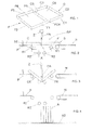
- the one-piece boxes (A) are composed of two boxed semi-boxes (F and C) in specular opposite position, each of them being provided with three lateral and vertical sides (F1, F2, F3 and C1, C2, C3) and connected by a fourth collapsible side (FC4) designed to act as hinge to turn the second boxed semi-box (C) over the first semi-box (F).
- F and C boxed semi-boxes
- the fourth side (FC4) is bordered by a transversal pair of creases (F5 and C5), each of them bordering the base (F6 and C6) of each boxed semi-box (F and C).
- the user In order to close the box, the user simply needs to turn the common side (FC4) up, rotating it by 90° upwards and around the first crease (C5), and turning the lid (C) over around the second crease (F5) in such a way to bring the semi-box (C) above the bottom (F), with the three sides (F1, F2 and F3) in external side-by-side position surrounded by the corresponding sides (C1, C2 and C3) of the lid (C).
- Machines are currently available to close the said boxes (A) starting from a semi-finished product composed of the two boxed semi-boxes (F and C) with base (C6 and F6) aligned in coplanar position and also in coplanar position with the three vertical sides (F1, F2, F3 and C1, C2, C3) in upward position.
- Similar cardboard semi-finished products travel towards the folding station on a conveyor belt (N) that moves along a track bordered by two fixed lateral sides that guide the correct regular forward movement of the semi-finished products.
- N conveyor belt
- the folding station (SP) is situated immediately downstream the conveyor belt (N) and comprises a spaced pair of idler rolls (R1) arranged on the same plane as the conveyor belt (N), which receive and support the semi-finished product (S) that comes out of the conveyor belt (N).
- a plane (P) with a transversal edge (ST) that stops the semi-finished product (S) coming out of the conveyor belt (N) is provided downstream the spaced pair of idler rolls (R1).
- the distance (L) between the pair of idler rolls (R1) is approximately equal to half of the length of the semi-finished product (S) and each roll (R1) is positioned in such a way that when the semi-finished product (S) reaches the end of the forward movement against the transversal side (ST), each one of the boxed semi-boxes (C and F) is positioned above the corresponding idler roll (R1) that is in the centre of the bases (C6 and F6).
- the folding station (SP) comprises a second pair of idler rolls (R2) under the first pair of idler rolls (R1), which have a lower mutual distance than the distance between the upper pair of idler rolls (R1).
- the vertical plane (X-X) passing through the longitudinal axis of the fourth side (FC4) is a symmetrical plane for both pairs of rolls (R1 and R2).
- the folding station (SP) also comprises an actuator (Z) positioned in central position above the pairs of idler rolls (R1), which is designed to drive a folding blade (PA) that lays on a vertical plane into alternate vertical travels.
- the actuator (Z) is operated and the blade (PA) intercepts the fourth side (FC4) during its descending travel and drives it downwards.
- the blade (PA) folds the semi-finished product (S) by an angle of over 90° around the fourth side (FC4), as shown in fig. 3 , and simultaneously pushes it downwards until the external sides of the bases (F6 and C6) touch the pair of rolls (R2).
- the blade (PA) is returned upwards by the actuator (Z), while the rolls (R2) complete the folding operation by additional 90° of the semi-finished product (S), which is ejected under the pair of rolls (R2) in perfectly closed position.
- An unloading plane (N2) is positioned under the folding station (SP), where the boxes are positioned by the said device in closed vertical position, since the box comes out from the rolls (R2) in vertical position with side (FC4) facing downwards.
- the product may originate the imperfect closing of the box (A), may be trapped inside the pair of rolls (R1 or R2) or may be grabbed by the blade (PA), thus stopping the folding machine.
- the purpose of the present invention is to devise a folding and closing system for boxes, such as the ones of the type described above, which allows for loading the product inside the box before folding and closing.
- Another purpose of the present invention is to devise a folding and closing system for boxes that allows for using a cheaper folding machine than the ones that are currently available on the market.
- An additional purpose of the present invention is to devise a folding and closing system for boxes, characterised by quicker actuation than the existing systems, thus allowing for packing a higher number of boxes over the same time period.
- the purpose of the present invention is to devise a folding machine for the implementation of the innovative system of the present invention.
- the system of the invention uses one conveyor belt only, and more precisely the same conveyor belt that feeds the folding station with semi-finished products (S) in the configuration with both bases (F6 and C6) in mutual coplanar position and also in coplanar position with the common side (FC4), while the sides (F1, F2, F3 and C1, C2, C3) are in upward position.
- the lid (C) of the box is faced forwards along the travelling direction of the conveyor belt, and means designed to grab the moving lid (C) and turn it over by 180° above the bottom (F) are provided, in such a way to close the box (A) without interrupting its forward movement on the conveyor belt and without losing the horizontal position of the bottom (F) of the box on the conveyor belt.
- the semi-finished product (S) is moved on the conveyor belt with the bottom (F) facing forwards along the travelling direction, thus turning the bottom over the lid (C) by 180°.
- this operating mode is possible in case of products that are trapped or stopped on the bottom (F) in a stable way, so that they can be turned over by 180° without losing their exact position on the bottom (F).
- the folding system of the invention allows for loading the product to be packed inside the box (A) before folding and closing the semi-finished box (S), with great time and labour savings with respect to the current technique.
- a folding machine has been designed to implement the system of the invention, which is provided with purely mechanical operating means that are automatically actuated because of their interference with the semi-finished product that travels on the conveyor belt, so that the only power that is required and consumed is the power necessary to operate the conveyor belt.
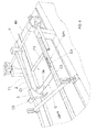
- the machine for the implementation of the system of the invention comprises a folding station (SP1) fed by a conveyor belt (N1) loaded with the semi-finished products (S) to be folded, with the lid (C) in forward position along the travelling direction of the said belt (N1).
- SP1 folding station
- N1 conveyor belt
- S semi-finished products
- C lid
- a portal structure (1 a and 1 b) is provided in the folding station (SP1), which is composed of a pair of identical lateral uprights (1 a), respectively arranged on the sides of the conveyor belt (N1), and of a cross-piece (1b) arranged above the conveyor belt (N1).
- An oscillating rod or rocker arm (2) is centrally fixed on the cross-piece (1 b) in perpendicular position, with the tip facing the travelling direction of the conveyor belt (N1).
- An arched claw (3) is mounted on the tip to hook the front border of the side (C2) of the semi-finished product (S), with the concavity of the claw (3) facing the side from which the semi-finished products (S) are provided.
- the tip of the claw (3) is shaped in such a way to be inserted under the front transversal side (C2).
- the lid (C) starts to turn over and as soon as it exceeds the 90° angle - which corresponds to the upper dead point of the oscillating rod (2), as shown in fig. 7 - the tip of the claw (3) tends to push the lid (C) downwards.
- the weight of the rod (2) makes the lid (C) complete the downward movement by additional 90°.
- the belt (N1) is provided with two lateral sides (SL) that act as guide for the correct controlled movement of the semi-finished products (S).
- the sides (SL) are provided with a pair of identical opposite internally protruding tongues (L1), which are designed to slightly bend the sides (F1 and F3) of the bottom (F).
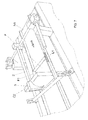
- the machine of the invention is also provided with a transversal bar (4) in horizontal position with adjustable height, downstream the claw (3), which is fixed to a suitable height from the belt (N1) to allow the box (A) to pass exactly under the bar (4).
- the bar (4) completely pushes down the lid (C) above the bottom (F) when the upper surface (C6) of the lid (C) interferes with the lower profile of the transversal bar (4) during the forward movement of the box (A) on the conveyor belt (N1), as shown in fig. 8 .
Landscapes
- Engineering & Computer Science (AREA)
- Mechanical Engineering (AREA)
- Closing Of Containers (AREA)
Applications Claiming Priority (1)
| Application Number | Priority Date | Filing Date | Title |
|---|---|---|---|
| ITMC20070239 ITMC20070239A1 (it) | 2007-12-12 | 2007-12-12 | Sistema e macchina per la chiusura automatica di astucci in cartone monolitici, del tipo costituiti da un fondo e da un coperchio collegati da una sponda laterale in comune. |
Publications (1)
| Publication Number | Publication Date |
|---|---|
| EP2070821A1 true EP2070821A1 (de) | 2009-06-17 |
Family
ID=40315501
Family Applications (1)
| Application Number | Title | Priority Date | Filing Date |
|---|---|---|---|
| EP08169967A Withdrawn EP2070821A1 (de) | 2007-12-12 | 2008-11-26 | System und Maschine zum automatischen Schließen einstückiger Pappkartons der Art, die sich aus einem Boden und Deckel zusammensetzt, die durch eine gemeinsame Seite verbunden sind |
Country Status (2)
| Country | Link |
|---|---|
| EP (1) | EP2070821A1 (de) |
| IT (1) | ITMC20070239A1 (de) |
Cited By (1)
| Publication number | Priority date | Publication date | Assignee | Title |
|---|---|---|---|---|
| CN116692175A (zh) * | 2023-08-01 | 2023-09-05 | 山东海奥斯生物科技股份有限公司 | 一种胶原蛋白肠衣智能包装装置 |
Citations (3)
| Publication number | Priority date | Publication date | Assignee | Title |
|---|---|---|---|---|
| DE2260823A1 (de) * | 1972-12-13 | 1974-06-20 | Big Dutchman Int Ag | Vorrichtung zum verschliessen von eierkleinverpackungen |
| US3877205A (en) * | 1972-12-15 | 1975-04-15 | Vefi As | Packing machine |
| DE3143093A1 (de) * | 1981-10-30 | 1983-05-11 | Certus Maschinenbau Gmbh, 8900 Augsburg | Verfahren und vorrichtung zum mechanischen aufsetzen von stuelpdeckeln auf mit einer ware gefuellte stuelpboeden |
-
2007
- 2007-12-12 IT ITMC20070239 patent/ITMC20070239A1/it unknown
-
2008
- 2008-11-26 EP EP08169967A patent/EP2070821A1/de not_active Withdrawn
Patent Citations (3)
| Publication number | Priority date | Publication date | Assignee | Title |
|---|---|---|---|---|
| DE2260823A1 (de) * | 1972-12-13 | 1974-06-20 | Big Dutchman Int Ag | Vorrichtung zum verschliessen von eierkleinverpackungen |
| US3877205A (en) * | 1972-12-15 | 1975-04-15 | Vefi As | Packing machine |
| DE3143093A1 (de) * | 1981-10-30 | 1983-05-11 | Certus Maschinenbau Gmbh, 8900 Augsburg | Verfahren und vorrichtung zum mechanischen aufsetzen von stuelpdeckeln auf mit einer ware gefuellte stuelpboeden |
Cited By (2)
| Publication number | Priority date | Publication date | Assignee | Title |
|---|---|---|---|---|
| CN116692175A (zh) * | 2023-08-01 | 2023-09-05 | 山东海奥斯生物科技股份有限公司 | 一种胶原蛋白肠衣智能包装装置 |
| CN116692175B (zh) * | 2023-08-01 | 2023-12-05 | 山东海奥斯生物科技股份有限公司 | 一种胶原蛋白肠衣智能包装装置 |
Also Published As
| Publication number | Publication date |
|---|---|
| ITMC20070239A1 (it) | 2009-06-13 |
Similar Documents
| Publication | Publication Date | Title |
|---|---|---|
| US20240124174A1 (en) | Box template folding process and mechanisms | |
| US5531661A (en) | Carrier sleeve erecting apparatus and method | |
| CN103906683B (zh) | 用于在包装容器中充填产品的填充机以及对此的方法 | |
| JP6793823B2 (ja) | 段ボール箱などの包装容器の充填前にフラップを離間させる装置、及び該装置を備えた充填ステーション | |
| JPS5924922B2 (ja) | 包装機械 | |
| KR101209255B1 (ko) | 바타입 물품에 적합한 사이드 공급형 자동 포장방법과 그 카토너 | |
| KR20200047641A (ko) | 폭 폴딩 시스템 및 의류 물품을 접는 방법 | |
| US20150068163A1 (en) | Apparatus and method for reducing restoring forces of package sleeves in a filling machine | |
| CN105189296B (zh) | 包装机 | |
| CN109715502A (zh) | 用于抓取和折叠插入板的头部、插入装置、填充站以及用于抓取、折叠和装载插入板的方法 | |
| CN107963468A (zh) | 一种包装纸箱折叠堆垛装置 | |
| JP4361196B2 (ja) | カートンの製造(折り曲げ)装置 | |
| US5308056A (en) | Apparatus for stacking flat workpieces on a stacking table | |
| US5957825A (en) | Parallelepiped carton forming machine | |
| RU2507132C2 (ru) | Способ и устройство для упаковки порционных продуктов в заготовку для упаковки | |
| KR20220037469A (ko) | 2차 포장용 포장 장치 | |
| KR200444565Y1 (ko) | 포장 카톤의 내향 꺾음부 접기장치 | |
| CN118083225B (zh) | 一种料仓式雪茄输送套袋系统 | |
| NL2036340B1 (en) | Case Erector Apparatus and Method for Erecting Left-Handed or Right-Handed Cases | |
| US20230234805A1 (en) | Method and apparatus for folding a stack of sheets | |
| ITMC20070239A1 (it) | Sistema e macchina per la chiusura automatica di astucci in cartone monolitici, del tipo costituiti da un fondo e da un coperchio collegati da una sponda laterale in comune. | |
| EP1584556B1 (de) | Vorrichtung und Verfahren zum Einfalten der Verschlussklappen einer Verpackung | |
| JP4377668B2 (ja) | 包装機の折り込み装置 | |
| KR101473618B1 (ko) | 포장박스의 포밍장치 | |
| ITBO990550A1 (it) | Macchina confezionatrice di prodotti in confezioni del tipo astucci . |
Legal Events
| Date | Code | Title | Description |
|---|---|---|---|
| PUAI | Public reference made under article 153(3) epc to a published international application that has entered the european phase |
Free format text: ORIGINAL CODE: 0009012 |
|
| AK | Designated contracting states |
Kind code of ref document: A1 Designated state(s): AT BE BG CH CY CZ DE DK EE ES FI FR GB GR HR HU IE IS IT LI LT LU LV MC MT NL NO PL PT RO SE SI SK TR |
|
| AX | Request for extension of the european patent |
Extension state: AL BA MK RS |
|
| AKX | Designation fees paid | ||
| REG | Reference to a national code |
Ref country code: DE Ref legal event code: 8566 |
|
| STAA | Information on the status of an ep patent application or granted ep patent |
Free format text: STATUS: THE APPLICATION IS DEEMED TO BE WITHDRAWN |
|
| 18D | Application deemed to be withdrawn |
Effective date: 20091218 |