EP2071060B1 - Einkristall-Herstellungsverfahren - Google Patents
Einkristall-Herstellungsverfahren Download PDFInfo
- Publication number
- EP2071060B1 EP2071060B1 EP07791100.6A EP07791100A EP2071060B1 EP 2071060 B1 EP2071060 B1 EP 2071060B1 EP 07791100 A EP07791100 A EP 07791100A EP 2071060 B1 EP2071060 B1 EP 2071060B1
- Authority
- EP
- European Patent Office
- Prior art keywords
- set value
- power ratio
- temperature
- value
- crystal
- Prior art date
- Legal status (The legal status is an assumption and is not a legal conclusion. Google has not performed a legal analysis and makes no representation as to the accuracy of the status listed.)
- Active
Links
Images




Classifications
-
- C—CHEMISTRY; METALLURGY
- C30—CRYSTAL GROWTH
- C30B—SINGLE-CRYSTAL GROWTH; UNIDIRECTIONAL SOLIDIFICATION OF EUTECTIC MATERIAL OR UNIDIRECTIONAL DEMIXING OF EUTECTOID MATERIAL; REFINING BY ZONE-MELTING OF MATERIAL; PRODUCTION OF A HOMOGENEOUS POLYCRYSTALLINE MATERIAL WITH DEFINED STRUCTURE; SINGLE CRYSTALS OR HOMOGENEOUS POLYCRYSTALLINE MATERIAL WITH DEFINED STRUCTURE; AFTER-TREATMENT OF SINGLE CRYSTALS OR A HOMOGENEOUS POLYCRYSTALLINE MATERIAL WITH DEFINED STRUCTURE; APPARATUS THEREFOR
- C30B15/00—Single-crystal growth by pulling from a melt, e.g. Czochralski method
- C30B15/20—Controlling or regulating
-
- C—CHEMISTRY; METALLURGY
- C30—CRYSTAL GROWTH
- C30B—SINGLE-CRYSTAL GROWTH; UNIDIRECTIONAL SOLIDIFICATION OF EUTECTIC MATERIAL OR UNIDIRECTIONAL DEMIXING OF EUTECTOID MATERIAL; REFINING BY ZONE-MELTING OF MATERIAL; PRODUCTION OF A HOMOGENEOUS POLYCRYSTALLINE MATERIAL WITH DEFINED STRUCTURE; SINGLE CRYSTALS OR HOMOGENEOUS POLYCRYSTALLINE MATERIAL WITH DEFINED STRUCTURE; AFTER-TREATMENT OF SINGLE CRYSTALS OR A HOMOGENEOUS POLYCRYSTALLINE MATERIAL WITH DEFINED STRUCTURE; APPARATUS THEREFOR
- C30B15/00—Single-crystal growth by pulling from a melt, e.g. Czochralski method
- C30B15/14—Heating of the melt or the crystallised materials
-
- Y—GENERAL TAGGING OF NEW TECHNOLOGICAL DEVELOPMENTS; GENERAL TAGGING OF CROSS-SECTIONAL TECHNOLOGIES SPANNING OVER SEVERAL SECTIONS OF THE IPC; TECHNICAL SUBJECTS COVERED BY FORMER USPC CROSS-REFERENCE ART COLLECTIONS [XRACs] AND DIGESTS
- Y10—TECHNICAL SUBJECTS COVERED BY FORMER USPC
- Y10T—TECHNICAL SUBJECTS COVERED BY FORMER US CLASSIFICATION
- Y10T117/00—Single-crystal, oriented-crystal, and epitaxy growth processes; non-coating apparatus therefor
- Y10T117/10—Apparatus
- Y10T117/1004—Apparatus with means for measuring, testing, or sensing
-
- Y—GENERAL TAGGING OF NEW TECHNOLOGICAL DEVELOPMENTS; GENERAL TAGGING OF CROSS-SECTIONAL TECHNOLOGIES SPANNING OVER SEVERAL SECTIONS OF THE IPC; TECHNICAL SUBJECTS COVERED BY FORMER USPC CROSS-REFERENCE ART COLLECTIONS [XRACs] AND DIGESTS
- Y10—TECHNICAL SUBJECTS COVERED BY FORMER USPC
- Y10T—TECHNICAL SUBJECTS COVERED BY FORMER US CLASSIFICATION
- Y10T117/00—Single-crystal, oriented-crystal, and epitaxy growth processes; non-coating apparatus therefor
- Y10T117/10—Apparatus
- Y10T117/1004—Apparatus with means for measuring, testing, or sensing
- Y10T117/1008—Apparatus with means for measuring, testing, or sensing with responsive control means
-
- Y—GENERAL TAGGING OF NEW TECHNOLOGICAL DEVELOPMENTS; GENERAL TAGGING OF CROSS-SECTIONAL TECHNOLOGIES SPANNING OVER SEVERAL SECTIONS OF THE IPC; TECHNICAL SUBJECTS COVERED BY FORMER USPC CROSS-REFERENCE ART COLLECTIONS [XRACs] AND DIGESTS
- Y10—TECHNICAL SUBJECTS COVERED BY FORMER USPC
- Y10T—TECHNICAL SUBJECTS COVERED BY FORMER US CLASSIFICATION
- Y10T117/00—Single-crystal, oriented-crystal, and epitaxy growth processes; non-coating apparatus therefor
- Y10T117/10—Apparatus
- Y10T117/1024—Apparatus for crystallization from liquid or supercritical state
- Y10T117/1032—Seed pulling
-
- Y—GENERAL TAGGING OF NEW TECHNOLOGICAL DEVELOPMENTS; GENERAL TAGGING OF CROSS-SECTIONAL TECHNOLOGIES SPANNING OVER SEVERAL SECTIONS OF THE IPC; TECHNICAL SUBJECTS COVERED BY FORMER USPC CROSS-REFERENCE ART COLLECTIONS [XRACs] AND DIGESTS
- Y10—TECHNICAL SUBJECTS COVERED BY FORMER USPC
- Y10T—TECHNICAL SUBJECTS COVERED BY FORMER US CLASSIFICATION
- Y10T117/00—Single-crystal, oriented-crystal, and epitaxy growth processes; non-coating apparatus therefor
- Y10T117/10—Apparatus
- Y10T117/1024—Apparatus for crystallization from liquid or supercritical state
- Y10T117/1032—Seed pulling
- Y10T117/1068—Seed pulling including heating or cooling details [e.g., shield configuration]
-
- Y—GENERAL TAGGING OF NEW TECHNOLOGICAL DEVELOPMENTS; GENERAL TAGGING OF CROSS-SECTIONAL TECHNOLOGIES SPANNING OVER SEVERAL SECTIONS OF THE IPC; TECHNICAL SUBJECTS COVERED BY FORMER USPC CROSS-REFERENCE ART COLLECTIONS [XRACs] AND DIGESTS
- Y10—TECHNICAL SUBJECTS COVERED BY FORMER USPC
- Y10T—TECHNICAL SUBJECTS COVERED BY FORMER US CLASSIFICATION
- Y10T117/00—Single-crystal, oriented-crystal, and epitaxy growth processes; non-coating apparatus therefor
- Y10T117/10—Apparatus
- Y10T117/1024—Apparatus for crystallization from liquid or supercritical state
- Y10T117/1076—Apparatus for crystallization from liquid or supercritical state having means for producing a moving solid-liquid-solid zone
- Y10T117/1088—Apparatus for crystallization from liquid or supercritical state having means for producing a moving solid-liquid-solid zone including heating or cooling details
Definitions
- the present invention relates to a single crystal manufacturing method according to the Czochralski method (the CZ method).
- the density of interstitial oxygen (hereinafter termed "Oi") is one very important product characteristic for determining the performance of a semiconductor device.
- the Oi density is determined during the pulling up process for a silicon single crystal according to the CZ method.
- the rotational speeds of the crucible and the crystal, and the flow rate of an inactive gas such as argon or the like within the chamber and so on are used as manufacturing parameters.
- an inactive gas such as argon or the like
- the Oi control range is widened by using a multiple heaters.
- the obverse of this is that the controllability of the crystal diameter becomes bad, and the actual diameter sometimes becomes excessively great as compared to the required diameter and sometimes becomes excessively small; and, as a result, the product yield rate becomes bad.
- JP 9 118585 A is directed to automate a stage for growing a single crystal, to pull up the single crystal free from crystal defects with good reproducibility and to rapidly pull up the single crystal.
- a seed crystal is brought into contact with a melt and the time before this seed crystal melts down is measured when the temp. of the melt surface is higher than an optimum temp.
- the temperature is lowered according to the measured time.
- the time before the crystal diameter attains a prescribed diameter is measured when the temp. of the melt surface is lower than the optimum temp.
- the temperature of the melt surface is raised according to this time.
- the temperature of the melt surface is pinpointed to the optimum temperature for seeding by repeating such correction processing.
- the average pulling-up speed to a set length is calculated during the course of pulling up of the dash neck of the single crystal in the pulling up of the single crystal at the optimized temp. of the melt surface and the melt temp. is further corrected.
- the stage for growing the single crystal is automated and the single crystal free from the crystal defects is pulled up with the good reproducibility.
- US-A-5,485,802 discloses a crucible which is situated in a vacuum chamber and provided with a feeder for granulate material, heating elements for melting the material, and a crystal puller above the crucible. Measuring elements provide signals for a controller including a fuzzy processor utilizing an empirically determined data field to output a signal for the material feeder.
- WO 99/63134 A1 relates to a device and method for growing crystals.
- the signals which come from a neuronal network are superimposed on the control signals provided for a PID controller.
- single-crystals and polycrystals having a very high quality with regard to the outer shape and inner constitution are obtained.
- the actual values of process data for example the melting temperature, the gas pressure, the fusion level, the gas flow and the like are3 sampled during the crystal growth process.
- the control is with stored program which obtains the actual values supplied detected of the sensors.
- a neuro Fuzzy logic is used, and adjustable devices like heaters, pumps, pulling mechanisms, rotary motors, valves are controlled over PID controllers.
- US 2006/005761 A1 provides a method and system for producing semiconductor grade single crystals that are substantially free of undesirable agglomerated defects.
- a vacancy/interstial (VII) boundary simulator analyzes various melt-solid interface shapes to predict a corresponding V/I transition curve for each of the various melt-solid interface shapes.
- a target melt-solid interface shape corresponding to a substantially flat V/I curve is identified for each of a plurality of axial positions along the length of the crystal.
- Target operating parameters to achieve each of the identified melt-solid interface shapes are stored in a melt-solid interfaced shape profile.
- a control system is responsive to the stored profile to generate one or more control signals to control one or more output devices such that the melt-solid interfaced shape substantially follows the target shapes as defined by the profile during crystal growth.
- the main difficulty in applying the CZ growth technique to SBN stems from an instability of the crystal diameter that is primarily attributed to faceted radial growth.
- the instability is a principal limiting factor in obtaining large, constant diameter boules.
- ADC temperature-based automatic diameter control
- the radial growth process is analyzed for the purpose of modelling the corresponding weight signal. In doing so, the standard equations governing the meniscus dynamics (neglecting heat balance) have been modified to accommodate a situation of rapidly-varying diameter.
- a digital ADC algorithm is presented along with a discussion of noise sources and filtering techniques. Finally, typical results for growth of SNB are given.
- a third crystal was grown with the normal automatic diameter control system activated simultaneously with auxiliary heating of the melt surface. It was concluded that the proposed technique was feasible for diameter control, and that the microscopic homogeneity could be improved. Macroscopic dopant profiles were affected by large changes of the heater power, indicating that convection in the system could be influenced.
- the method of the invention comprises the features of claim 1.
- Preferred embodiments of the invention are characterized in the sub-claims.
- said power ratio set value is arranged for said power ratio set value to change according to the ' state of progression of the crystal pulling up process, and for said variable power ratio temperature set value to change along with the change of said power ratio set value, so as to become a temperature value which corresponds to the current value of said power ratio set value.
- the electrical power to the multiple heaters changes according to the power ratio set value, but the measured value of the applied heat temperature changes according to change of this power ratio, and this constitutes a disturbance to the diameter control.
- a fixed power ratio temperature set value corresponding to one fixed power ratio is not used, but rather a variable power ratio temperature set value is employed, which changes along with change of the power ratio set value.
- This variable power ratio temperature set value changes during the crystal pulling up process, so as to become a temperature value which corresponds to the current value of the power ratio set value.
- variable power ratio temperature set value can be set so as to compensate more effectively for the disturbance caused by change of the measured value of the applied heat temperature due to change of the power ratio. As a result, when multiple heaters are provided, the controllability of the crystal diameter is enhanced.
- variable power ratio temperature set value is set so as to compensate for change of the measured value of said applied heat temperature which occurs due to change of said power ratio set value.
- a data table may be prepared in advance, in which is defined a relationship between the measured value of said applied heat temperature which changes according to change of said power ratio set value during the crystal pulling up process, and the position of said crystal at the time point that the measured values are obtained (i.e. the crystal pulling up length), and the variable power ratio temperature set value may be set on the basis of this data table.
- variable power ratio temperature set value for example, a profile may be employed in which, when the power ratio set value changes from a first ratio value to a different second ratio value, the variable power ratio temperature set value shifts from a first fixed power ratio temperature set value which corresponds to said first ratio, to a second fixed power ratio temperature set value which corresponds to said second ratio.
- the control device may be adapted to control said pulling up speed so as to bring the measured value of said diameter close to said diameter set value, to determine a temperature target value by adjusting said variable power ratio temperature set value so as to bring the measured value of said pulling up speed close to said speed set value, and to control the electrical power to said multiple heaters so as to bring the measured value of said applied heat temperature close to said temperature target value, while making the power ratio of said multiple heaters agree with said power ratio set value.
- the control device may be adapted to set a variable power ratio temperature set value which is determined in advance, and to store it; or, alternatively, it may be adapted to calculate the variable power ratio temperature set value automatically, on the basis of information which specifies a relationship between said power ratio and said applied heat temperature, and said power ratio set value.
- the profile of the power ratio set value also changes if the specification of the crystal manufacturing apparatus or the specification of the crystal which it is desired to manufacture changes, still, if the control device is adapted to calculate the variable power ratio temperature set value automatically on the basis of the power ratio set value, as described above, then this control device is able simply and easily to answer to changes of the specification of the crystal manufacturing apparatus or the specification of the crystal which it is desired to manufacture.
- the melt temperature is changed and the crystal diameter is controlled, principally by adjusting the electrical power supplied to the heater.
- the temperature of the heater itself, or the temperature of a heat shield which surrounds the heater is measured with an optical temperature measurement device (a pyrometer) or the like, and the heater electrical power is controlled so that this measured temperature matches a temperature set value which is programmed in advance.
- the profile of the temperature set value is set so as to change along a curve which is specified according to the pulling up length of the crystal during the pulling up process (in other words, according to the state of progression of the pulling up process).
- the temperature program is set in advance so as to take into account temperature fluctuations due to change of the anticipated power ratio of the heaters. Due to this, the controllability of the crystal diameter is improved almost to a level which compares favorably with that of a single heater type apparatus, and the product yield rate is also enhanced.
- the crystal manufacturing method according to this embodiment will be explained in concrete terms with reference to the drawing.
- Fig. 1 shows the main structure of a chamber portion of the crystal manufacturing apparatus.
- a hot zone 13 is installed in a chamber 12 of this crystal manufacturing apparatus 10, and a crucible 14 is disposed within the hot zone 13.
- the hot zone 13 comprises multiple heaters, arranged along the vertical direction around the neighborhood of the crucible 14, for example two stage heaters - an upper heater 16 and a lower heater 18.
- the heaters 16 and 18 are made from carbon and generate heat by electric heating, and a raw material liquid melt 20 is created in the crucible 14 by this heating.
- a seed crystal is attached to the end of a pulling up wire 24, this seed crystal is dipped into the raw material liquid melt 20, and thereafter, by winding up the pulling up wire 24, a single crystal 22 which grows from the seed crystal is continuously pulled up.
- the number of stages of the heaters 16 and 18 is not limited to being two; there could also be more thereof, and moreover it would also be acceptable to include, not only these heaters in the neighborhood of the side wall of the crucible 14, but also a so-called bottom heater which is disposed in the neighborhood of the bottom surface of the crucible 14.
- the hot zone 13 also comprises a heat shield tube 26 which is disposed above the heaters 16 and 18 and the crucible 14, a heat shield 28 and an insulation tube 30 which surround the side surfaces of the heaters 16 and 18, and a spill tray 32 which is disposed below the heaters 16 and 18 and the crucible 14, and these are also made from carbon.
- a glass window 34 is formed in the side wall of the chamber 12, just at a height which corresponds to the upper heater 16, and a through hole is opened through the insulation tube 30 at a spot which corresponds to this glass window 34.
- a pyrometer 36 is disposed outside the glass window 34, and this pyrometer 36 passes through a hole pierced in the glass window 34, thus being adapted to measure the temperature of the heat shield 28 in the neighborhood of the upper heater 16.
- the temperature which is the subject of measurement here need only be a temperature which changes along with change of the electrical power supplied to the heaters 16 and 18, so that, from this aspect, it does not need to be the temperature of the heat shield 28; it may also be the temperature of the heater 16 or that of the heater 18, or the temperature of the crucible 14. In any of these cases, the temperature which is the subject of being measured here will hereinafter be termed the "applied heat temperature", with the meaning that it is a temperature which is generated by the heat applied by the heaters 16 and 18.
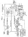
- Fig. 2 shows the main structure of a control device of the crystal manufacturing apparatus.
- this control device 11 for the crystal manufacturing apparatus 10 comprises a diameter setter 90, a speed setter 92, a temperature setter 94, and a power ratio setter 96, which respectively set a diameter set value, a speed set value, a temperature set value, and a power ratio set value.
- these setters 90, 92, 94, and 96 may be implemented using one or a plurality of storage devices which store diameter set values, speed set values, temperature set values, and power ratio set values which have been set (programmed) in advance, in the format of, for example, data tables or the like.
- the diameter set value is a target value for the diameter of the single crystal 22.
- the speed set value is a target value for the pulling up speed of the single crystal 22.
- the temperature set value is a "fundamental" target value for the applied heat temperature, and this takes the applied heat temperature value when the seed is dipped as a reference, and is expressed as a temperature difference (in other words, a relative temperature) with respect to this reference.
- the power ratio set value is a target value for the power ratio of the heaters 16 and 18 (in this specification, the ratio of the electrical power of the upper heater to the total electrical power of the upper heater 16 and the lower heater 18 is used).
- the temperature set value is set so as to have a specified profile which changes according to the pulling up length of the crystal 22 during the pulling up process (in other word, according to the state of progression of the pulling up process).
- the power ratio set value is also set so as to have a specified profile which changes according to the pulling up length of the crystal 22 during the crystal pulling up process.
- this control device 11 comprises a diameter controller 40, a speed controller 50, and a temperature controller 60.
- Each of the diameter controller 40, the speed controller 50, and the temperature controller 60 is a controller which is adapted to calculate an actuation value for performing PID calculation for the deviation between a set value and a feedback value.
- the diameter controller 40 compares the value of the diameter of the crystal 22 at the liquid surface, which is detected by a diameter detection camera 42 (hereinafter termed the "actual diameter value"), with a diameter set value which is programmed in advance, and controls the pulling up speed of the crystal 22 with the crystal elevating/lowering motor 44, so that the pulling up speed is reduced if the actual diameter value is less than the diameter set value, and so that the pulling up speed is increased, if the actual diameter is greater than the diameter set value.
- the diameter controller 40 obtains a speed command value by performing predetermined PID calculation upon the deviation between the actual diameter value and the diameter target value, and outputs this speed command value to the crystal elevating/lowering motor 44.
- the crystal 22 is thus pulled up at a speed according to this speed command value.
- the method for measuring the diameter of the crystal 22 the method of using the diameter detection camera 42 described above is only one method given by way of example; it would also be possible to utilize some other method, for example the "diameter detection method by weight" of measuring the weight change of the crystal 22 per unit time period, and deriving its diameter therefrom, or the like.
- the speed controller 50 ascertains the value of the actual pulling up speed (hereinafter termed the "actual speed value") from the signal from an encoder 46 which is coupled to the crystal elevating/lowering motor 44, and compares this actual speed value with a speed set value which is programmed in advance.
- the speed controller 50 and the temperature controller 60 are combined, so that control of the applied heat temperature is performed so as to bring the actual speed value close to the speed set value.
- the speed controller 50 calculates a temperature regulated value so that the actual speed value comes close to the speed set value, by performing predetermined PID calculation upon the deviation between the actual speed value and the speed set value.
- This temperature regulated value is inputted to an adder 52, and is added to a temperature set value which is programmed in advance.
- the temperature controller 60 compares together the actual value of the applied heat temperature as measured by the pyrometer 36 (hereinafter this will be termed the "actual temperature value"), and the above described final temperature target value, and outputs a power command value so as to bring the actual temperature value close to the temperature target value.
- the temperature controller 60 calculates a power command value for bringing the actual temperature value close to the temperature target value, by performing predetermined PID calculation upon the deviation between the actual temperature value and the temperature target value, and inputs this power command value to a power calculator 62.
- the power calculator 62 inputs the power ratio set value, and, along with making the power ratio of the upper and lower heaters 16 and 18 accord with the power ratio set value, also calculates an upper heater power command value and a lower heater power command value so that the total electrical power of the upper and lower heaters 16 and 18 agrees with the power command value, and outputs the upper heater power command value and the lower heater power command value to an upper heater power supply 64 and a lower heater power supply 66 respectively.
- the upper heater power supply 64 and the lower heater power supply 66 control supply of electrical power to the upper heater 16 and supply of electrical power to the lower heater 18, respectively, so as to agree with the upper heater power command value and the lower heater power command value, respectively.
- cascade control is performed in which: with regard to the crystal diameter, the pulling up speed is controlled so as to bring the actual diameter of the crystal 22 close to the diameter set value; on the other hand, with regard to the applied heat temperature, the temperature set value is adjusted and the temperature target value is determined, so as to bring the pulling up speed of the crystal 22 close to the speed set value; and the heater electrical power is controlled so as to bring the actual temperature of the applied heat temperature close to the temperature target value.
- the reason for employing this type of control method is as follows.
- the time constant for the applied heat temperature is large (in other words, it takes quite a time from when the applied heat temperature changes until the crystal diameter changes), accordingly this is suitable for being used as a parameter for determining the crystal shape on the macro level.
- the time constant for the pulling up speed is small (it takes a relatively short time period from when the pulling up speed changes until the crystal diameter changes), accordingly this is suitable for being used as a parameter for controlling the crystal diameter immediately as required, in response to disturbances to the control, which occur continuously.
- control device 11 which employs the control method described above; it could also be applied to a control device which employs some other type of method.
- Fig. 3 shows examples of the relationship between the applied heat temperature measured by the pyrometer 36, and the power ratio, for different pulling up lengths A, B, and C.
- the pulling up lengths A, B, and C in Fig. 3 correspond, respectively, to the pulling up lengths A, B, and C shown in Fig. 4 which will be described hereinafter.
- the measured value by the pyrometer 36 of the applied heat temperature changes when the power ratio changes, even if the total electrical power to the upper and lower heaters 16 and 18 remains the same. Moreover, this measured applied heat temperature also varies according to the pulling up length. When this type of difference of the measured temperature due to the power ratio is taken into consideration, it is seen that, if the power ratio is different, then the appropriate temperature set value must also be different.
- Fig. 4 shows examples of appropriate temperature set values corresponding to various different power ratios. It should be understood that, for the convenience of explanation, the example shown in the figure has been simplified as compared with reality.
- each of these temperature set values 70, 72, and 74 will be termed a "fixed power ratio temperature set value", with the meaning that it is the appropriate temperature set value corresponding to some one fixed power ratio.
- the fixed power ratio temperature set value 70, 72, or 74 shown in Fig. 4 is not itself employed, but rather a temperature set value which can adapt according to the variable power ratio, created based upon that fixed power ratio temperature set value 70, 72, or 74, is employed (hereinafter, this will be termed the "variable power ratio temperature set value").
- Fig. 5 shows an example of a profile of the variable power ratio temperature set value which is used in this embodiment, together with an example of a profile of the power ratio set value.
- the reference number 80 denotes the variable power ratio temperature set value
- the reference number 82 denotes the power ratio set value
- the power ratio set value 82 changes according to the crystal pulling up length, for example, first to 0.7, next to 0.3, and finally to 0.5.
- the variable power ratio temperature set value 80 changes along with this type of change of the power ratio set value, and is set so as to agree with the fixed power ratio temperature set value 70, 72, or 74, according to the power ratio set value 82 at the present time point.
- variable power ratio temperature set value 80 is set so as to shift from a fixed power ratio temperature set value which corresponds to this first ratio value, to a fixed power ratio temperature set value which corresponds to the second ratio value (for example, from the set value 70 to the set value 74, or from the set value 74 to the set value 72).
- the variable power ratio temperature set value 80 is set so as to have a profile in which change of the measured value of the applied heat temperature due to change of the power ratio set value has been taken into account, as shown in Fig. 3 .
- a method may be employed of preparing in advance, within the power ratio setter 96, a data table in which the relationship between the measured values of the applied heat temperature, as it changes according to change of the power ratio set value during the crystal pulling up process, and the position of the crystal (i.e. the crystal pulling up length) at the time point that each of these measured values was obtained, is defined, and the power ratio setter 96 setting the variable power ratio temperature set value on the basis of this data table (for example, reading out from this data table a variable power ratio temperature set value which has been stored therein in advance).
- variable power ratio temperature set value 80 which has a profile in which change of the applied heat temperature along with change of the power ratio set value is taken into account in this manner, the control device 11 shown in Fig. 2 is able to compensate for disturbance due to the temperature changing due to change of the power ratio, so that the controllability of the crystal diameter can be improved.
- the variable power ratio temperature set value 80 in this embodiment takes the applied heat temperature value when the seed is dipped as a reference, and is expressed as a temperature difference with respect to that reference (in other words, as a relative temperature).
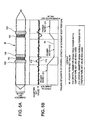
- Figs. 6A and 6B show some results of testing the advantageous effects of enhancing the diameter controllability, according to this embodiment.
- the power ratio was set as shown by the reference number 82 in Fig. 6B (or Fig. 5 ).
- two crystals 22 were experimentally prepared using this power ratio 82, one when one fixed power ratio temperature set value was used as the temperature set value, and one when the variable power ratio temperature set value 80 according to this embodiment shown in Fig. 5 was used as the temperature set value.
- Fig. 6A shows an example of the shape of a crystal 22 which was manufactured in this test, when one fixed power ratio temperature set value was used as the temperature set value.
- Fig. 6B shows the diameter values 110 of this crystal 22 (the one shown in Fig.
- the value 110 of the diameter of the crystal 22 is unstable, and sometimes exceeds the diameter set value by more than the permitted value (the crystal portion 100 shown in Fig. 6A ), while sometimes also being less than the diameter set value by more than the permitted value (the crystal portion 102 shown in Fig. 6A ).
- prominent errors of diameter occur after the time points at which change of the power ratio takes place.
- the variable power ratio temperature set value 80 according to this embodiment is employed, deviations of the diameter value 112 from the diameter set value are kept extremely small, and the diameter value 112 is controlled to be in the vicinity of the diameter set value in a stable manner.
- variable power ratio temperature set value is determined in advance and set by being stored in the control device 11, as a variant example, it would also be acceptable to provide, in the control device 11, a device which calculates the variable power ratio temperature set value.
- Fig. 7 shows an example of the structure of a device for calculating the variable power ratio temperature set value.
- this calculation device 120 comprises a power ratio profile determination unit 122 and a temperature profile conversion unit 124.
- the power ratio profile determination unit 122 is a device which determines a profile for the power ratio set value.
- the temperature profile conversion unit 124 is a device which determines a profile for the variable power ratio temperature set value, on the basis of the profile of the power ratio set value from the power ratio profile determination unit 122.
- the power ratio profile determination unit 122 inputs a plurality of predetermined parameter values which are to be taken into consideration in the determination of the power ratio set value, such as the target oxygen density (Oi), the type of the hot zone, the raw material weight, the crystal rotational speed, the crucible rotational speed, the gas flow rate and the pressure within the chamber, the magnetic field intensity and position, and so on.
- the power ratio profile determination unit 122 contains a lookup table (or function) 150 in which the relationship between these various input parameters and the power ratio is determined in advance, and, by applying the input values of the above described plurality of parameters to this lookup table (or function) 150, a power ratio set value is calculated which has a profile best matching the above described set of input values of the plurality of parameters.
- this temperature profile conversion unit 124 inputs the profile which has been calculated by the power ratio profile determination unit 122.
- this temperature profile conversion unit 124 has a lookup table (or function) 152 in which a profile for the fixed temperature set value which is suitable for this power ratio is defined, and, by applying the above described power ratio set value which has been inputted to this lookup table (or function) 152, a variable power ratio temperature set value is calculated which has a profile that, along with change of the power ratio according to the power ratio set value, shifts from a fixed temperature set value which was appropriate for the power ratio value before change, to a fixed temperature set value which is appropriate for the power ratio value after change.
- this type of calculation device 120 By installing this type of calculation device 120 to the control device 11, it becomes possible to respond to changes of the specification of the crystal manufacturing apparatus and changes of the specification of the crystal which it is desired to manufacture, in a simple and easy manner. In other words while, if the specification of the crystal manufacturing apparatus or the specification of the crystal which it is desired to manufacture is different, the profile of the power ratio set value also becomes different, if the control device is adapted to calculate the variable power ratio temperature set value automatically as described above, then this control device will be able to respond automatically to different power ratio set values. Moreover, by using this type of control device, during the crystal pulling up process, according to the current value of the power ratio, it is also possible to calculate and to output the current position of the variable power ratio temperature set value in real time.
Landscapes
- Chemical & Material Sciences (AREA)
- Engineering & Computer Science (AREA)
- Crystallography & Structural Chemistry (AREA)
- Materials Engineering (AREA)
- Metallurgy (AREA)
- Organic Chemistry (AREA)
- Crystals, And After-Treatments Of Crystals (AREA)
Claims (4)
- Einkristall-Herstellungsverfahren nach dem Czochralski-Verfahren umfassend:Anlegen von Wärme an einen Tiegel (14) mit mehreren Heizeinrichtungen (16, 18), die eine obere (16) und eine untere (18) Heizeinrichtung umfassen;Aufwärtsziehen eines Kristalls (22) von dem Tiegel (14);Messen einer angelegten Heiztemperatur, die durch die Wärme erzeugt wird, die von den Heizeinrichtungen (16, 18) angelegt wird,Messen des Durchmessers des Kristalls (22) und Messen der Aufwärtsziehgeschwindigkeit des Kristalls (22);Einstellen eines Durchmessersollwertes, eines Geschwindigkeitssollwertes und eines variablen Temperatursollwertes (80);Steuern der Aufwärtsziehgeschwindigkeit und der elektrischen Leistung der Vielzahl der Heizeinrichtungen (16, 18) in Abhängigkeit von den gemessenen Werten der angelegten Wärmetemperatur, dem Durchmesser und der Aufwärtsziehgeschwindigkeit und von dem Durchmessersollwert, dem Geschwindigkeitssollwert und dem variablen Temperatursollwert (80); undVerändern des Leistungsverhältnis-Sollwertes (82) entsprechend dem Fortschreitungszustand des Kristallziehverfahrens,dadurch gekennzeichnet, dassdas Messen der angelegten Wärmetemperatur, das Messen der Temperatur eines Wärmeschilds in der Nachbarschaft der oberen Heizeinrichtung umfasst;der Leistungsverhältnis-Sollwert (82) des Leistungsverhältnisses eingestellt wird aus der elektrischen Leistung der oberen Heizeinrichtung (16) zu der gesamten elektrischen Leistung der oberen Heizeinrichtung (16) und der unteren Heizeinrichtung (18), wobei die obere Heizeinrichtung (16) und die untere Heizeinrichtung (18) entlang einer vertikalen Richtung um die Nachbarschaft des Tiegels (14) herum angeordnet sind;der variable Temperatursollwert (80) gesteuert wird, um den Leistungsverhältnis-Sollwert (82) entsprechend dem Fortschreitungszustand des Kristallziehverfahrens zu verändern, und um das Leistungsverhältnis der mehreren Heizeinrichtungen (16, 18) in Übereinstimmung mit dem Leistungsverhältnis-Sollwert (82) zu bringen,und dass der variable Temperatursollwert (80) eingestellt und berechnet wird aus:einer vordefinierten Sauerstoffdichte-Leistungsverhältnis-Nachschlagetabelle (150), die das Verhältnis zwischen den Eingabeparametem spezifiziert, die bei der Bestimmung des Leistungsverhältnis-Sollwertes in Betracht gezogen werden sollen und die die Zielsauerstoffdichte, den Typ der heißen Zone, das Rohmaterialgewicht, die Kristalldrehgeschwindigkeit, die Tiegeldrehgeschwindigkeit, die Gasflussrate, den Druck in der Kammer, die magnetische Feldintensität und das vorab bestimmte Leistungsverhältnis umfassen, wobei der Leistungsverhältnis-Sollwert (82) berechnet wird durch eingeben von Eingabewerten der oben erwähnten Vielzahl von Parametern in die Sauerstoffdichte-Leistungsverhältnis-Nachschlagetabelle (150) und von einer vordefinierten Leistungsverhältnis-Temperaturesollwert-Nachschlagetabelle (152), in der ein Profil des festgelegten Temperatursollwertes gegenüber dem Leistungsverhältnis definiert ist, wobei ein variabler Temperatursollwert (80) berechnet wird, der ein Profil hat, das zusammen mit einer Änderung des Leistungsverhältnisses entsprechend dem Leistungsverhältnis-Sollwert (82) von einem festgelegten Temperatursollwert, der für den Leistungsverhältniswert vor der Veränderung angemessen war, zu einem festgelegten Temperatursollwert verschoben wird,der für den Leistungsverhältniswert nach der Veränderung angemessen ist, indem für jedes unterschiedliche Leistungsverhältnis der Leistungsverhältnis-Sollwert (82) von der Leistungsverhältnis-Profil-Bestimmungseinheit (122) auf die Leistungsverhältnis-Temperatursollwert-Nachschlagetabelle (152) angewendet wird,wobei der variable Temperatursollwert (80) ein Profil hat, bei dem die angewendete Temperatur sich mit der Änderung des Leistungsverhältnis-Sollwertes (82) ändert und zu einem Temperaturwert wird, der dem gegenwärtigen Wert des Leistungsverhältnis-Sollwertes (82) entspricht, und worinder variable Temperatursollwert (80) eine Änderung der angewendeten Heiztemperatur kompensiert, die aufgrund einer Änderung des Leistungsverhältnis-Sollwertes (82) auftritt.
- Einkristall-Herstellungsverfahren nach Anspruch 1, worin der variable Temperatursollwert (80) in Abhängigkeit von der Leistungsverhältnis-Temperatur-Nachschlagetabelle (152) eingestellt wird, in der ein Verhältnis zwischen dem gemessenen Wert der angelegten Wärmetemperatur, die sich entsprechend der Änderung des Leistungsverhältnis-Sollwertes (82) ändert, und der Position des Kristalls (22) an dem Zeitpunkt definiert ist, an dem die Messwerte erhalten werden.
- Einkristall-Herstellungsverfahren nach Anspruch 1, worin, wenn der Leistungsverhältnis-Sollwert sich von einem ersten Verhältniswert zu einem zweiten Verhältniswert ändert, der variable Temperatursollwert (80) von einem ersten festgelegten Temperatursollwert (70 oder 74), der dem ersten Verhältniswert entspricht, zu einem zweiten festgelegten Leistungsverhältnis-Temperatursollwert (74 oder 72) verschoben wird, der dem zweiten Verhältniswert entspricht.
- Einkristall-Herstellungsverfahren, nach Anspruch 1, worin die Aufwärtsziehgeschwindigkeit gesteuert wird, um den gemessenen Wert des Durchmessers nahe zu dem Durchmessersollwert zu bringen, wobei ein Temperatursollwert bestimmt wird, in dem der variable Temperatursollwert eingestellt wird, um den Messwert der Aufwärtsziehgeschwindigkeit nahe zu dem zweiten Geschwindigkeitssollwert zu bringen, und wobei die elektrische Leistung der mehreren Heizeinrichtungen (16, 18) gesteuert wird, um den Messwert der angelegten Heizungstemperatur nahe zu dem Temperatursollwert zu bringen, während das Leistungsverhältnis der mehreren Heizeinrichtungen (16, 18) in Übereinstimmung mit dem Leistungsverhältnis-Sollwert (82) gebracht wird.
Applications Claiming Priority (2)
| Application Number | Priority Date | Filing Date | Title |
|---|---|---|---|
| JP2006262632A JP5073257B2 (ja) | 2006-09-27 | 2006-09-27 | 単結晶製造装置及び方法 |
| PCT/JP2007/064363 WO2008038450A1 (fr) | 2006-09-27 | 2007-07-20 | Appareil et procédé de fabrication d'un monocristal |
Publications (3)
| Publication Number | Publication Date |
|---|---|
| EP2071060A1 EP2071060A1 (de) | 2009-06-17 |
| EP2071060A4 EP2071060A4 (de) | 2010-09-01 |
| EP2071060B1 true EP2071060B1 (de) | 2014-10-08 |
Family
ID=39229890
Family Applications (1)
| Application Number | Title | Priority Date | Filing Date |
|---|---|---|---|
| EP07791100.6A Active EP2071060B1 (de) | 2006-09-27 | 2007-07-20 | Einkristall-Herstellungsverfahren |
Country Status (5)
| Country | Link |
|---|---|
| US (1) | US8216371B2 (de) |
| EP (1) | EP2071060B1 (de) |
| JP (1) | JP5073257B2 (de) |
| TW (1) | TW200815628A (de) |
| WO (1) | WO2008038450A1 (de) |
Families Citing this family (9)
| Publication number | Priority date | Publication date | Assignee | Title |
|---|---|---|---|---|
| US20100024717A1 (en) | 2008-07-31 | 2010-02-04 | Benno Orschel | Reversed action diameter control in a semiconductor crystal growth system |
| DE102009056638B4 (de) * | 2009-12-02 | 2013-08-01 | Siltronic Ag | Verfahren zum Ziehen eines Einkristalls aus Silizium mit einem Abschnitt mit gleich bleibendem Durchmesser |
| JP5708171B2 (ja) * | 2010-04-26 | 2015-04-30 | 株式会社Sumco | シリコン単結晶引き上げ装置及びシリコン単結晶の製造方法 |
| JP5552891B2 (ja) * | 2010-05-12 | 2014-07-16 | 信越半導体株式会社 | 単結晶製造装置および単結晶の製造方法 |
| KR101759003B1 (ko) * | 2015-12-30 | 2017-07-17 | 주식회사 엘지실트론 | 실리콘 단결정 성장 방법 |
| JP7184025B2 (ja) * | 2019-12-06 | 2022-12-06 | 株式会社Sumco | シリコン単結晶の製造方法 |
| CN113622017B (zh) * | 2020-05-09 | 2024-11-19 | 鄂尔多斯市隆基硅材料有限公司 | 一种单晶硅掺杂方法及单晶硅制造方法 |
| CN115584557A (zh) * | 2022-11-08 | 2023-01-10 | 晶科能源股份有限公司 | 一种温度控制方法和设备、单晶炉 |
| CN116145240A (zh) * | 2022-12-30 | 2023-05-23 | 上海新昇半导体科技有限公司 | 一种晶体生长的控制方法、装置、系统及计算机存储介质 |
Family Cites Families (14)
| Publication number | Priority date | Publication date | Assignee | Title |
|---|---|---|---|---|
| JPS515993B2 (de) * | 1971-10-18 | 1976-02-24 | ||
| JPH0669917B2 (ja) * | 1982-10-08 | 1994-09-07 | 住友電気工業株式会社 | 複数段ヒ−タ−の制御方法 |
| JPS6046993A (ja) * | 1983-08-23 | 1985-03-14 | Sumitomo Electric Ind Ltd | 単結晶引上装置 |
| JPS62153191A (ja) | 1985-12-27 | 1987-07-08 | Mitsubishi Metal Corp | 単結晶引き上げ装置 |
| JP2681115B2 (ja) * | 1989-02-14 | 1997-11-26 | 住友シチックス株式会社 | 単結晶製造方法 |
| DE4301072B4 (de) * | 1993-01-16 | 2006-08-24 | Crystal Growing Systems Gmbh | Verfahren zum Ziehen von Einkristallen aus einer Schmelze |
| JPH09118585A (ja) * | 1995-10-26 | 1997-05-06 | Kokusai Electric Co Ltd | 単結晶引上装置および単結晶の引上方法 |
| DE19824838A1 (de) * | 1998-06-04 | 1999-12-09 | Leybold Systems Gmbh | Verfahren zum Herstellen von Kristallen |
| JP2000203987A (ja) | 1999-01-14 | 2000-07-25 | Toshiba Ceramics Co Ltd | 単結晶製造装置 |
| DE19959416C1 (de) * | 1999-12-09 | 2001-03-15 | Freiberger Compound Mat Gmbh | Heizelement zum Beheizen von Schmelztiegeln und Anordnung von Heizelementen |
| JP2002321995A (ja) * | 2001-04-23 | 2002-11-08 | Mitsui Chemicals Inc | 単結晶の育成方法 |
| DE10220964B4 (de) * | 2002-05-06 | 2006-11-02 | Pv Silicon Forschungs- Und Produktions Ag | Anordnung zur Herstellung von Kristallstäben mit definiertem Querschnitt und kolumnarer polykristalliner Struktur mittels tiegelfreier kontinuierlicher Kristallisation |
| WO2005095680A1 (ja) * | 2004-03-31 | 2005-10-13 | Komatsu Denshi Kinzoku Kabushiki Kaisha | 半導体単結晶製造装置および黒鉛るつぼ |
| US20060005761A1 (en) * | 2004-06-07 | 2006-01-12 | Memc Electronic Materials, Inc. | Method and apparatus for growing silicon crystal by controlling melt-solid interface shape as a function of axial length |
-
2006
- 2006-09-27 JP JP2006262632A patent/JP5073257B2/ja active Active
-
2007
- 2007-07-20 EP EP07791100.6A patent/EP2071060B1/de active Active
- 2007-07-20 WO PCT/JP2007/064363 patent/WO2008038450A1/ja not_active Ceased
- 2007-07-20 US US12/311,111 patent/US8216371B2/en active Active
- 2007-08-01 TW TW096128180A patent/TW200815628A/zh unknown
Also Published As
| Publication number | Publication date |
|---|---|
| TW200815628A (en) | 2008-04-01 |
| JP5073257B2 (ja) | 2012-11-14 |
| TWI354717B (de) | 2011-12-21 |
| WO2008038450A1 (fr) | 2008-04-03 |
| EP2071060A1 (de) | 2009-06-17 |
| US20090293800A1 (en) | 2009-12-03 |
| EP2071060A4 (de) | 2010-09-01 |
| JP2008081352A (ja) | 2008-04-10 |
| US8216371B2 (en) | 2012-07-10 |
Similar Documents
| Publication | Publication Date | Title |
|---|---|---|
| JP5601801B2 (ja) | 単結晶シリコンインゴットの成長方法および成長用装置 | |
| US6241818B1 (en) | Method and system of controlling taper growth in a semiconductor crystal growth process | |
| US6726764B2 (en) | Method for controlling growth of a silicon crystal to minimize growth rate and diameter deviations | |
| EP0536405B1 (de) | Verfahren zum ziehen von einkristallen | |
| US8216371B2 (en) | Single crystal manufacturing apparatus and method | |
| TWI740669B (zh) | 晶棒生長控制方法以及控制系統 | |
| JP4380537B2 (ja) | シリコン単結晶を製造する方法 | |
| KR101623644B1 (ko) | 잉곳 성장장치의 온도제어장치 및 그 제어방법 | |
| US5968263A (en) | Open-loop method and system for controlling growth of semiconductor crystal | |
| JP2003512282A (ja) | 半導体結晶の成長を制御する方法 | |
| US5164039A (en) | Apparatus for controlling the diameter of silicon single crystal | |
| KR20100102844A (ko) | 고품질 실리콘 단결정 제조 방법 및 장치 | |
| US7582160B2 (en) | Silicone single crystal production process | |
| US5246535A (en) | Method and apparatus for controlling the diameter of a silicon single crystal | |
| JPH04219388A (ja) | シリコン単結晶の直径制御方法及び装置 | |
| JP2019094251A (ja) | 単結晶製造方法 | |
| TWI897110B (zh) | 晶體生長的控制方法、裝置、系統及電腦存儲媒體 | |
| KR101366726B1 (ko) | 단결정 실리콘 잉곳 제조 장치 및 방법 | |
| CN121653837A (zh) | 控制半导体单晶生长的方法、装置、及晶棒 | |
| JP7628952B2 (ja) | 融液から円筒状結晶を引き上げる方法 | |
| CN121675079A (zh) | 拉晶工艺的功率控制方法、装置、设备及计算机存储介质 | |
| CN118910717A (zh) | 单晶硅收尾控制方法 | |
| CN119392352A (zh) | 单晶生长方法、控制装置和单晶生长装置 |
Legal Events
| Date | Code | Title | Description |
|---|---|---|---|
| PUAI | Public reference made under article 153(3) epc to a published international application that has entered the european phase |
Free format text: ORIGINAL CODE: 0009012 |
|
| 17P | Request for examination filed |
Effective date: 20090424 |
|
| AK | Designated contracting states |
Kind code of ref document: A1 Designated state(s): AT BE BG CH CY CZ DE DK EE ES FI FR GB GR HU IE IS IT LI LT LU LV MC MT NL PL PT RO SE SI SK TR |
|
| AX | Request for extension of the european patent |
Extension state: AL BA HR MK RS |
|
| RIC1 | Information provided on ipc code assigned before grant |
Ipc: G05B 11/42 20060101ALI20100715BHEP Ipc: C30B 15/20 20060101AFI20080421BHEP |
|
| A4 | Supplementary search report drawn up and despatched |
Effective date: 20100729 |
|
| 17Q | First examination report despatched |
Effective date: 20110405 |
|
| DAX | Request for extension of the european patent (deleted) | ||
| REG | Reference to a national code |
Ref country code: DE Ref legal event code: R079 Ref document number: 602007038833 Country of ref document: DE Free format text: PREVIOUS MAIN CLASS: C30B0015200000 Ipc: C30B0015140000 |
|
| GRAP | Despatch of communication of intention to grant a patent |
Free format text: ORIGINAL CODE: EPIDOSNIGR1 |
|
| RIC1 | Information provided on ipc code assigned before grant |
Ipc: C30B 15/20 20060101ALI20140415BHEP Ipc: C30B 15/14 20060101AFI20140415BHEP |
|
| INTG | Intention to grant announced |
Effective date: 20140520 |
|
| GRAS | Grant fee paid |
Free format text: ORIGINAL CODE: EPIDOSNIGR3 |
|
| GRAP | Despatch of communication of intention to grant a patent |
Free format text: ORIGINAL CODE: EPIDOSNIGR1 |
|
| GRAA | (expected) grant |
Free format text: ORIGINAL CODE: 0009210 |
|
| INTG | Intention to grant announced |
Effective date: 20140821 |
|
| AK | Designated contracting states |
Kind code of ref document: B1 Designated state(s): AT BE BG CH CY CZ DE DK EE ES FI FR GB GR HU IE IS IT LI LT LU LV MC MT NL PL PT RO SE SI SK TR |
|
| REG | Reference to a national code |
Ref country code: GB Ref legal event code: FG4D |
|
| REG | Reference to a national code |
Ref country code: AT Ref legal event code: REF Ref document number: 690684 Country of ref document: AT Kind code of ref document: T Effective date: 20141015 Ref country code: CH Ref legal event code: EP |
|
| REG | Reference to a national code |
Ref country code: IE Ref legal event code: FG4D |
|
| REG | Reference to a national code |
Ref country code: DE Ref legal event code: R096 Ref document number: 602007038833 Country of ref document: DE Effective date: 20141120 |
|
| REG | Reference to a national code |
Ref country code: NL Ref legal event code: VDEP Effective date: 20141008 |
|
| REG | Reference to a national code |
Ref country code: AT Ref legal event code: MK05 Ref document number: 690684 Country of ref document: AT Kind code of ref document: T Effective date: 20141008 |
|
| REG | Reference to a national code |
Ref country code: LT Ref legal event code: MG4D |
|
| PG25 | Lapsed in a contracting state [announced via postgrant information from national office to epo] |
Ref country code: NL Free format text: LAPSE BECAUSE OF FAILURE TO SUBMIT A TRANSLATION OF THE DESCRIPTION OR TO PAY THE FEE WITHIN THE PRESCRIBED TIME-LIMIT Effective date: 20141008 |
|
| PG25 | Lapsed in a contracting state [announced via postgrant information from national office to epo] |
Ref country code: FI Free format text: LAPSE BECAUSE OF FAILURE TO SUBMIT A TRANSLATION OF THE DESCRIPTION OR TO PAY THE FEE WITHIN THE PRESCRIBED TIME-LIMIT Effective date: 20141008 Ref country code: PT Free format text: LAPSE BECAUSE OF FAILURE TO SUBMIT A TRANSLATION OF THE DESCRIPTION OR TO PAY THE FEE WITHIN THE PRESCRIBED TIME-LIMIT Effective date: 20150209 Ref country code: LT Free format text: LAPSE BECAUSE OF FAILURE TO SUBMIT A TRANSLATION OF THE DESCRIPTION OR TO PAY THE FEE WITHIN THE PRESCRIBED TIME-LIMIT Effective date: 20141008 Ref country code: ES Free format text: LAPSE BECAUSE OF FAILURE TO SUBMIT A TRANSLATION OF THE DESCRIPTION OR TO PAY THE FEE WITHIN THE PRESCRIBED TIME-LIMIT Effective date: 20141008 Ref country code: IS Free format text: LAPSE BECAUSE OF FAILURE TO SUBMIT A TRANSLATION OF THE DESCRIPTION OR TO PAY THE FEE WITHIN THE PRESCRIBED TIME-LIMIT Effective date: 20150208 |
|
| PG25 | Lapsed in a contracting state [announced via postgrant information from national office to epo] |
Ref country code: AT Free format text: LAPSE BECAUSE OF FAILURE TO SUBMIT A TRANSLATION OF THE DESCRIPTION OR TO PAY THE FEE WITHIN THE PRESCRIBED TIME-LIMIT Effective date: 20141008 Ref country code: SE Free format text: LAPSE BECAUSE OF FAILURE TO SUBMIT A TRANSLATION OF THE DESCRIPTION OR TO PAY THE FEE WITHIN THE PRESCRIBED TIME-LIMIT Effective date: 20141008 Ref country code: GR Free format text: LAPSE BECAUSE OF FAILURE TO SUBMIT A TRANSLATION OF THE DESCRIPTION OR TO PAY THE FEE WITHIN THE PRESCRIBED TIME-LIMIT Effective date: 20150109 Ref country code: LV Free format text: LAPSE BECAUSE OF FAILURE TO SUBMIT A TRANSLATION OF THE DESCRIPTION OR TO PAY THE FEE WITHIN THE PRESCRIBED TIME-LIMIT Effective date: 20141008 Ref country code: PL Free format text: LAPSE BECAUSE OF FAILURE TO SUBMIT A TRANSLATION OF THE DESCRIPTION OR TO PAY THE FEE WITHIN THE PRESCRIBED TIME-LIMIT Effective date: 20141008 Ref country code: CY Free format text: LAPSE BECAUSE OF FAILURE TO SUBMIT A TRANSLATION OF THE DESCRIPTION OR TO PAY THE FEE WITHIN THE PRESCRIBED TIME-LIMIT Effective date: 20141008 |
|
| REG | Reference to a national code |
Ref country code: DE Ref legal event code: R097 Ref document number: 602007038833 Country of ref document: DE |
|
| PG25 | Lapsed in a contracting state [announced via postgrant information from national office to epo] |
Ref country code: EE Free format text: LAPSE BECAUSE OF FAILURE TO SUBMIT A TRANSLATION OF THE DESCRIPTION OR TO PAY THE FEE WITHIN THE PRESCRIBED TIME-LIMIT Effective date: 20141008 Ref country code: SK Free format text: LAPSE BECAUSE OF FAILURE TO SUBMIT A TRANSLATION OF THE DESCRIPTION OR TO PAY THE FEE WITHIN THE PRESCRIBED TIME-LIMIT Effective date: 20141008 Ref country code: DK Free format text: LAPSE BECAUSE OF FAILURE TO SUBMIT A TRANSLATION OF THE DESCRIPTION OR TO PAY THE FEE WITHIN THE PRESCRIBED TIME-LIMIT Effective date: 20141008 Ref country code: CZ Free format text: LAPSE BECAUSE OF FAILURE TO SUBMIT A TRANSLATION OF THE DESCRIPTION OR TO PAY THE FEE WITHIN THE PRESCRIBED TIME-LIMIT Effective date: 20141008 Ref country code: RO Free format text: LAPSE BECAUSE OF FAILURE TO SUBMIT A TRANSLATION OF THE DESCRIPTION OR TO PAY THE FEE WITHIN THE PRESCRIBED TIME-LIMIT Effective date: 20141008 |
|
| PLBE | No opposition filed within time limit |
Free format text: ORIGINAL CODE: 0009261 |
|
| STAA | Information on the status of an ep patent application or granted ep patent |
Free format text: STATUS: NO OPPOSITION FILED WITHIN TIME LIMIT |
|
| 26N | No opposition filed |
Effective date: 20150709 |
|
| PG25 | Lapsed in a contracting state [announced via postgrant information from national office to epo] |
Ref country code: SI Free format text: LAPSE BECAUSE OF FAILURE TO SUBMIT A TRANSLATION OF THE DESCRIPTION OR TO PAY THE FEE WITHIN THE PRESCRIBED TIME-LIMIT Effective date: 20141008 Ref country code: MC Free format text: LAPSE BECAUSE OF FAILURE TO SUBMIT A TRANSLATION OF THE DESCRIPTION OR TO PAY THE FEE WITHIN THE PRESCRIBED TIME-LIMIT Effective date: 20141008 |
|
| REG | Reference to a national code |
Ref country code: CH Ref legal event code: PL |
|
| GBPC | Gb: european patent ceased through non-payment of renewal fee |
Effective date: 20150720 |
|
| PG25 | Lapsed in a contracting state [announced via postgrant information from national office to epo] |
Ref country code: LU Free format text: LAPSE BECAUSE OF FAILURE TO SUBMIT A TRANSLATION OF THE DESCRIPTION OR TO PAY THE FEE WITHIN THE PRESCRIBED TIME-LIMIT Effective date: 20150720 |
|
| REG | Reference to a national code |
Ref country code: IE Ref legal event code: MM4A |
|
| PG25 | Lapsed in a contracting state [announced via postgrant information from national office to epo] |
Ref country code: LI Free format text: LAPSE BECAUSE OF NON-PAYMENT OF DUE FEES Effective date: 20150731 Ref country code: GB Free format text: LAPSE BECAUSE OF NON-PAYMENT OF DUE FEES Effective date: 20150720 Ref country code: CH Free format text: LAPSE BECAUSE OF NON-PAYMENT OF DUE FEES Effective date: 20150731 |
|
| REG | Reference to a national code |
Ref country code: FR Ref legal event code: ST Effective date: 20160331 |
|
| PG25 | Lapsed in a contracting state [announced via postgrant information from national office to epo] |
Ref country code: FR Free format text: LAPSE BECAUSE OF NON-PAYMENT OF DUE FEES Effective date: 20150731 |
|
| PG25 | Lapsed in a contracting state [announced via postgrant information from national office to epo] |
Ref country code: IE Free format text: LAPSE BECAUSE OF NON-PAYMENT OF DUE FEES Effective date: 20150720 |
|
| PG25 | Lapsed in a contracting state [announced via postgrant information from national office to epo] |
Ref country code: MT Free format text: LAPSE BECAUSE OF FAILURE TO SUBMIT A TRANSLATION OF THE DESCRIPTION OR TO PAY THE FEE WITHIN THE PRESCRIBED TIME-LIMIT Effective date: 20141008 |
|
| PG25 | Lapsed in a contracting state [announced via postgrant information from national office to epo] |
Ref country code: BG Free format text: LAPSE BECAUSE OF FAILURE TO SUBMIT A TRANSLATION OF THE DESCRIPTION OR TO PAY THE FEE WITHIN THE PRESCRIBED TIME-LIMIT Effective date: 20141008 Ref country code: HU Free format text: LAPSE BECAUSE OF FAILURE TO SUBMIT A TRANSLATION OF THE DESCRIPTION OR TO PAY THE FEE WITHIN THE PRESCRIBED TIME-LIMIT; INVALID AB INITIO Effective date: 20070720 |
|
| PG25 | Lapsed in a contracting state [announced via postgrant information from national office to epo] |
Ref country code: TR Free format text: LAPSE BECAUSE OF FAILURE TO SUBMIT A TRANSLATION OF THE DESCRIPTION OR TO PAY THE FEE WITHIN THE PRESCRIBED TIME-LIMIT Effective date: 20141008 |
|
| PG25 | Lapsed in a contracting state [announced via postgrant information from national office to epo] |
Ref country code: BE Free format text: LAPSE BECAUSE OF FAILURE TO SUBMIT A TRANSLATION OF THE DESCRIPTION OR TO PAY THE FEE WITHIN THE PRESCRIBED TIME-LIMIT Effective date: 20141008 |
|
| PGFP | Annual fee paid to national office [announced via postgrant information from national office to epo] |
Ref country code: DE Payment date: 20250722 Year of fee payment: 19 |
|
| PGFP | Annual fee paid to national office [announced via postgrant information from national office to epo] |
Ref country code: IT Payment date: 20250724 Year of fee payment: 19 |