EP2071121A2 - Alignement de terrain pour échelles et supports d'échafaudage - Google Patents
Alignement de terrain pour échelles et supports d'échafaudage Download PDFInfo
- Publication number
- EP2071121A2 EP2071121A2 EP08021591A EP08021591A EP2071121A2 EP 2071121 A2 EP2071121 A2 EP 2071121A2 EP 08021591 A EP08021591 A EP 08021591A EP 08021591 A EP08021591 A EP 08021591A EP 2071121 A2 EP2071121 A2 EP 2071121A2
- Authority
- EP
- European Patent Office
- Prior art keywords
- traverse
- spars
- legs
- leg
- guide
- Prior art date
- Legal status (The legal status is an assumption and is not a legal conclusion. Google has not performed a legal analysis and makes no representation as to the accuracy of the status listed.)
- Withdrawn
Links
- 230000003068 static effect Effects 0.000 claims description 4
- 238000010073 coating (rubber) Methods 0.000 claims description 2
- 239000004020 conductor Substances 0.000 claims 1
- 239000002184 metal Substances 0.000 claims 1
- 239000000725 suspension Substances 0.000 description 5
- NJPPVKZQTLUDBO-UHFFFAOYSA-N novaluron Chemical compound C1=C(Cl)C(OC(F)(F)C(OC(F)(F)F)F)=CC=C1NC(=O)NC(=O)C1=C(F)C=CC=C1F NJPPVKZQTLUDBO-UHFFFAOYSA-N 0.000 description 4
- 238000006073 displacement reaction Methods 0.000 description 3
- 235000003332 Ilex aquifolium Nutrition 0.000 description 2
- 241000209027 Ilex aquifolium Species 0.000 description 2
- XAGFODPZIPBFFR-UHFFFAOYSA-N aluminium Chemical compound [Al] XAGFODPZIPBFFR-UHFFFAOYSA-N 0.000 description 2
- 229910052782 aluminium Inorganic materials 0.000 description 2
- 239000002991 molded plastic Substances 0.000 description 2
- 229920001875 Ebonite Polymers 0.000 description 1
- 230000006978 adaptation Effects 0.000 description 1
- 210000003746 feather Anatomy 0.000 description 1
- 239000012510 hollow fiber Substances 0.000 description 1
- 238000004519 manufacturing process Methods 0.000 description 1
- 238000010137 moulding (plastic) Methods 0.000 description 1
- 210000001331 nose Anatomy 0.000 description 1
- 239000004033 plastic Substances 0.000 description 1
- 230000002787 reinforcement Effects 0.000 description 1
- 239000007787 solid Substances 0.000 description 1
- 239000006228 supernatant Substances 0.000 description 1
Images



Classifications
-
- E—FIXED CONSTRUCTIONS
- E06—DOORS, WINDOWS, SHUTTERS, OR ROLLER BLINDS IN GENERAL; LADDERS
- E06C—LADDERS
- E06C7/00—Component parts, supporting parts, or accessories
- E06C7/42—Ladder feet; Supports therefor
- E06C7/44—Means for mounting ladders on uneven ground
-
- E—FIXED CONSTRUCTIONS
- E04—BUILDING
- E04G—SCAFFOLDING; FORMS; SHUTTERING; BUILDING IMPLEMENTS OR AIDS, OR THEIR USE; HANDLING BUILDING MATERIALS ON THE SITE; REPAIRING, BREAKING-UP OR OTHER WORK ON EXISTING BUILDINGS
- E04G1/00—Scaffolds primarily resting on the ground
- E04G1/24—Scaffolds primarily resting on the ground comprising essentially special base constructions; comprising essentially special ground-engaging parts, e.g. inclined struts, wheels
Definitions
- the present invention has for its object to provide a continuous terrain compensation without the disadvantages described, which requires only minimal intervention of the user to adjust and is safe.
- an adaptation to sloping or uneven terrain without additionally carried devices or tools may be possible.
- the device must be easy to manufacture.
- the traverse is designed so long that it connects and is held by the spars, e.g. is pushed through breakthroughs in the bars.
- the traverse is made short, so that it can be moved entirely between the bars.
- Held the cross member in claim 2 of a guide device which is attached to the bottom rung and forms a kind of cage in which parts of the traverse can move laterally.
- the legs do not necessarily consist of straight bars. It it must only be ensured that there is sufficient freedom of movement in the area of the leg guide.
- the surfaces on which the traverse and its support or guide device touch influence the properties of the device. This fact will be taken up in the further remarks.
- An arrangement with the mentioned properties can be produced, for example, simply from aluminum profiles in connection with some plastic moldings.
- the height compensation is achieved in that the legs of the legs change their height when the suspension points are moved laterally.
- the foot of the right leg undergoes a curve according to Fig. 1 (Control curve).
- the curve for the left leg is obtained by mirroring the right leg trajectory, with one leg reaching its maximum height just when the other one has its minimum.
- the exact course of the curves varies depending on the geometric conditions. From the control curve, taking into account further boundary conditions, such as the maximum desired leg steepness and the at least to be achieved stand broadening, a maximum height adjustment Y and the necessary adjustment X of the traverse are taken.
- the device automatically adjusts the terrain compensation when wiping the ladder:
- the too deep standing leg touches the ground and pushes the traverse both upwards and in the direction of the other leg on further weaning. This causes itself too low a stand up and the other base moves down, which is exactly what you want.
- the ladder can only be lowered as far as the existing play allows. The traverse is now pressed by the weight of the ladder and because of the leverage on the legs against the lower guide surfaces.
- the device can of course be adjusted by a displacement of the crossbar by hand.
- the easy adjustability may possibly be improved by springs or a mechanism that pushes the crossbar in the unloaded state upwards.
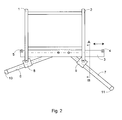
- the chosen variant of the device Fig. 2 is characterized by the fact that it also respects the side view Fig. 3 is perfectly symmetrical. It can be used in recesses on the undersides of the spars 1,2 .
- the traverse 3 consists of a U-shaped rod, the holes for attachment of the axles for the legs 6,7 and screwed at the ends handles 4,5 , which simultaneously form stops for the adjustment of the traverse.
- the crossbar of the crossbar may include a recess to facilitate adjustment by hand.
- a corrugation is attached to the bottom, so that there is a particularly high static friction is achieved.
- the brackets are corrugated in the region of the lower guide surfaces 13 , which, together with the corrugation on the cross member 3 causes the desired high static friction in the loaded state.
- a rubber coating could be applied or a hard rubber part could be used.
- legs 6,7 tubes can be used, which are provided for attachment in the upper part with a transverse bore and rounded so far that they can be pivoted after their assembly to the crossbar.
- a pedestal 10, 11 is attached.
- the axis therefore has a thread on the end faces.
- the leg guides 8,9 consist of short, pivoting at the lower ends the home-mounted hollow-fiber rods, which are provided with sliding inserts FIGS.
- the sliding inserts 16 can be glued or inserted. They may be provided at the ends with noses to prevent slipping.
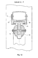
- the cross member 3 consists of a T-shaped rod whose transverse flange in a cage, which is formed of two riveted to the front and back of the lowest rung angle profiles 17, 18 , can be moved laterally .
- the protruding from the cage web of Traverse is provided with holes for the axes of the legs 6,7 . Between the holes may still be a handle 4 may be attached to facilitate the displacement of the crosshead.
- On the two lower sides of the flange 13, 14 of the traverse is a corrugation, mounted transversely to the direction of movement.
- the inner sides of the angle profiles which form the cage for the traverse are also corrugated transversely to the direction of movement. At all other contact surfaces, in particular between the top of the traverse and the rung the lowest possible friction is desirable. This can possibly be promoted by a left and right on the crossbar mounted plastic shoe.
- legs 6,7 tubes can be used, which are rounded for attachment in the upper part and provided with a transverse bore and a gap, so that the protruding from the cage web of the traverse inserted into the gap and connected to a transverse axis 15 can.
- the axle is fixed from both sides with screws and washers.
- additional molded plastic parts 19 may be embedded in the region of their suspension.
- the leg guides 8,9 correspond to those of the first embodiment.
Landscapes
- Engineering & Computer Science (AREA)
- Architecture (AREA)
- Mechanical Engineering (AREA)
- Civil Engineering (AREA)
- Structural Engineering (AREA)
- Ladders (AREA)
Applications Claiming Priority (2)
| Application Number | Priority Date | Filing Date | Title |
|---|---|---|---|
| DE200710061357 DE102007061357B3 (de) | 2007-12-14 | 2007-12-14 | Geländeausgleich für Leitern und Gerüstständer |
| DE200810049385 DE102008049385B3 (de) | 2007-12-14 | 2008-09-26 | Geländeausgleich für Leitern und Gerüstständer |
Publications (2)
| Publication Number | Publication Date |
|---|---|
| EP2071121A2 true EP2071121A2 (fr) | 2009-06-17 |
| EP2071121A3 EP2071121A3 (fr) | 2012-04-04 |
Family
ID=40266158
Family Applications (1)
| Application Number | Title | Priority Date | Filing Date |
|---|---|---|---|
| EP08021591A Withdrawn EP2071121A3 (fr) | 2007-12-14 | 2008-12-12 | Alignement de terrain pour échelles et supports d'échafaudage |
Country Status (2)
| Country | Link |
|---|---|
| EP (1) | EP2071121A3 (fr) |
| DE (1) | DE102008049385B3 (fr) |
Cited By (2)
| Publication number | Priority date | Publication date | Assignee | Title |
|---|---|---|---|---|
| GB2472198A (en) * | 2009-07-27 | 2011-02-02 | Joseph Trevor Sidaway | Stabilisation device for ladder |
| EP2142745A4 (fr) * | 2007-03-23 | 2012-05-02 | Landon Innovations Llc | Dispositif de mise à niveau d'échelle à réglage automatique |
Families Citing this family (1)
| Publication number | Priority date | Publication date | Assignee | Title |
|---|---|---|---|---|
| DE102020001940A1 (de) | 2020-03-26 | 2021-09-30 | Klaus-Peter Laube | Selbstregulierende Standvorrichtung für Leitern und Gerüstständer |
Citations (5)
| Publication number | Priority date | Publication date | Assignee | Title |
|---|---|---|---|---|
| FR1520525A (fr) | 1967-02-10 | 1968-04-12 | Support d'échelle réglable en inclinaison et largeur sur le sol | |
| DE10110405A1 (de) | 2001-03-01 | 2002-09-12 | Klaus-Peter Laube | Vorrichtung zum Ausgleich von Geländeunebenheiten und zur Standsicherung für Leitern und Gerüstständer |
| DE10109947A1 (de) | 2001-02-09 | 2002-09-19 | Loh Kg Hailo Werk | Leiter mit einem Niveauausgleich |
| DE10309762B3 (de) | 2003-02-28 | 2004-08-05 | Klaus-Peter Laube | Vorrichtung zur Standsicherung von Leitern und Gerüstständern auf unebenem Gelände |
| US20080230316A1 (en) | 2007-03-23 | 2008-09-25 | Landon Innovations Llc | Self-adjusting ladder leveling device |
Family Cites Families (1)
| Publication number | Priority date | Publication date | Assignee | Title |
|---|---|---|---|---|
| US4456095A (en) * | 1981-01-02 | 1984-06-26 | Milba Properties Pty. Ltd. | Levelling device for ladders |
-
2008
- 2008-09-26 DE DE200810049385 patent/DE102008049385B3/de active Active
- 2008-12-12 EP EP08021591A patent/EP2071121A3/fr not_active Withdrawn
Patent Citations (5)
| Publication number | Priority date | Publication date | Assignee | Title |
|---|---|---|---|---|
| FR1520525A (fr) | 1967-02-10 | 1968-04-12 | Support d'échelle réglable en inclinaison et largeur sur le sol | |
| DE10109947A1 (de) | 2001-02-09 | 2002-09-19 | Loh Kg Hailo Werk | Leiter mit einem Niveauausgleich |
| DE10110405A1 (de) | 2001-03-01 | 2002-09-12 | Klaus-Peter Laube | Vorrichtung zum Ausgleich von Geländeunebenheiten und zur Standsicherung für Leitern und Gerüstständer |
| DE10309762B3 (de) | 2003-02-28 | 2004-08-05 | Klaus-Peter Laube | Vorrichtung zur Standsicherung von Leitern und Gerüstständern auf unebenem Gelände |
| US20080230316A1 (en) | 2007-03-23 | 2008-09-25 | Landon Innovations Llc | Self-adjusting ladder leveling device |
Cited By (2)
| Publication number | Priority date | Publication date | Assignee | Title |
|---|---|---|---|---|
| EP2142745A4 (fr) * | 2007-03-23 | 2012-05-02 | Landon Innovations Llc | Dispositif de mise à niveau d'échelle à réglage automatique |
| GB2472198A (en) * | 2009-07-27 | 2011-02-02 | Joseph Trevor Sidaway | Stabilisation device for ladder |
Also Published As
| Publication number | Publication date |
|---|---|
| DE102008049385B3 (de) | 2010-04-01 |
| EP2071121A3 (fr) | 2012-04-04 |
Similar Documents
| Publication | Publication Date | Title |
|---|---|---|
| DE4305190B4 (de) | Schubmaststapler | |
| EP2452664B1 (fr) | Table d'opération | |
| DE2851987A1 (de) | Stuetzvorrichtung fuer leitern | |
| DE4232949A1 (de) | Hubvorrichtung | |
| EP2601349B1 (fr) | Système de rail avec ferrure de support destinée au support réglable en hauteur d'un rail de support et de guidage | |
| EP3880922A1 (fr) | Système de guidage pour le guidage d'un battant de porte monté de manière mobile | |
| EP3250498A1 (fr) | Dispositif de protection de charges | |
| WO2000059343A1 (fr) | Dispositif de guidage pour tiroirs | |
| DE102008049385B3 (de) | Geländeausgleich für Leitern und Gerüstständer | |
| DE102007061357B3 (de) | Geländeausgleich für Leitern und Gerüstständer | |
| DE102009051191A1 (de) | Nachrüstbares Rollenelement und Fuß für ein automatisches Lagersystem sowie Verfahren zum Verschieben eines automatischen Lagersystems | |
| EP2614028A2 (fr) | Dispositif de réception d'un profilé de tablier porte-fourche | |
| EP3144265B2 (fr) | Dispositif de levage avec un châssis | |
| EP2664469B1 (fr) | Timon de traction pour une remorque de véhicule utilitaire | |
| DE102004007568A1 (de) | Vorrichtung zur hängenden Anordnung einer Sicherheitsglasscheibe an einem Trägerprofil | |
| DE102009040850B4 (de) | Holzspalter | |
| DE102007058434B3 (de) | Adapter zur Umrüstung eines Fahrgerätes für eine Krankentrage, Bahre oder einen Sarg für den Transport des Sarges und Fahrgerät mit einem derartigen Adapter | |
| EP3144264B1 (fr) | Dispositif de levage | |
| EP1798108B1 (fr) | Guidage de coulissement d'arrêt | |
| DE202018005228U1 (de) | Rollvorrichtung für ein manuell handhabbares Steiggerät | |
| DE102009000636A1 (de) | Hubvorrichtung | |
| DE69114471T2 (de) | Ausbreitbarer Transportwagen und dazu passende Spuranordnung. | |
| DE4428550C2 (de) | Vorsatzgerät für Flurförderzeuge, insbesondere für Gabelstapler | |
| EP2251095A1 (fr) | Fixation de laquage de porte | |
| DE202007003491U1 (de) | Lageranordnung für Hubkettenrollen in einem Teleskophubgerüst für Hubstapler |
Legal Events
| Date | Code | Title | Description |
|---|---|---|---|
| PUAI | Public reference made under article 153(3) epc to a published international application that has entered the european phase |
Free format text: ORIGINAL CODE: 0009012 |
|
| AK | Designated contracting states |
Kind code of ref document: A2 Designated state(s): AT BE BG CH CY CZ DE DK EE ES FI FR GB GR HR HU IE IS IT LI LT LU LV MC MT NL NO PL PT RO SE SI SK TR |
|
| AX | Request for extension of the european patent |
Extension state: AL BA MK RS |
|
| PUAL | Search report despatched |
Free format text: ORIGINAL CODE: 0009013 |
|
| AK | Designated contracting states |
Kind code of ref document: A3 Designated state(s): AT BE BG CH CY CZ DE DK EE ES FI FR GB GR HR HU IE IS IT LI LT LU LV MC MT NL NO PL PT RO SE SI SK TR |
|
| AX | Request for extension of the european patent |
Extension state: AL BA MK RS |
|
| RIC1 | Information provided on ipc code assigned before grant |
Ipc: E04G 1/24 20060101ALI20120228BHEP Ipc: E06C 7/44 20060101AFI20120228BHEP |
|
| 17P | Request for examination filed |
Effective date: 20120716 |
|
| 17Q | First examination report despatched |
Effective date: 20120803 |
|
| AKX | Designation fees paid |
Designated state(s): AT BE BG CH CY CZ DE DK EE ES FI FR GB GR HR HU IE IS IT LI LT LU LV MC MT NL NO PL PT RO SE SI SK TR |
|
| STAA | Information on the status of an ep patent application or granted ep patent |
Free format text: STATUS: THE APPLICATION IS DEEMED TO BE WITHDRAWN |
|
| 18D | Application deemed to be withdrawn |
Effective date: 20150701 |