EP2071182B1 - A multiple energy inputs hydropower system - Google Patents
A multiple energy inputs hydropower system Download PDFInfo
- Publication number
- EP2071182B1 EP2071182B1 EP08002546A EP08002546A EP2071182B1 EP 2071182 B1 EP2071182 B1 EP 2071182B1 EP 08002546 A EP08002546 A EP 08002546A EP 08002546 A EP08002546 A EP 08002546A EP 2071182 B1 EP2071182 B1 EP 2071182B1
- Authority
- EP
- European Patent Office
- Prior art keywords
- water
- pressure
- energy
- main
- force
- Prior art date
- Legal status (The legal status is an assumption and is not a legal conclusion. Google has not performed a legal analysis and makes no representation as to the accuracy of the status listed.)
- Not-in-force
Links
Images


Classifications
-
- F—MECHANICAL ENGINEERING; LIGHTING; HEATING; WEAPONS; BLASTING
- F03—MACHINES OR ENGINES FOR LIQUIDS; WIND, SPRING, OR WEIGHT MOTORS; PRODUCING MECHANICAL POWER OR A REACTIVE PROPULSIVE THRUST, NOT OTHERWISE PROVIDED FOR
- F03B—MACHINES OR ENGINES FOR LIQUIDS
- F03B13/00—Adaptations of machines or engines for special use; Combinations of machines or engines with driving or driven apparatus; Power stations or aggregates
- F03B13/06—Stations or aggregates of water-storage type, e.g. comprising a turbine and a pump
-
- F—MECHANICAL ENGINEERING; LIGHTING; HEATING; WEAPONS; BLASTING
- F03—MACHINES OR ENGINES FOR LIQUIDS; WIND, SPRING, OR WEIGHT MOTORS; PRODUCING MECHANICAL POWER OR A REACTIVE PROPULSIVE THRUST, NOT OTHERWISE PROVIDED FOR
- F03B—MACHINES OR ENGINES FOR LIQUIDS
- F03B1/00—Engines of impulse type, i.e. turbines with jets of high-velocity liquid impinging on blades or like rotors, e.g. Pelton wheels; Parts or details peculiar thereto
-
- F—MECHANICAL ENGINEERING; LIGHTING; HEATING; WEAPONS; BLASTING
- F03—MACHINES OR ENGINES FOR LIQUIDS; WIND, SPRING, OR WEIGHT MOTORS; PRODUCING MECHANICAL POWER OR A REACTIVE PROPULSIVE THRUST, NOT OTHERWISE PROVIDED FOR
- F03B—MACHINES OR ENGINES FOR LIQUIDS
- F03B17/00—Other machines or engines
- F03B17/005—Installations wherein the liquid circulates in a closed loop ; Alleged perpetua mobilia of this or similar kind
-
- F—MECHANICAL ENGINEERING; LIGHTING; HEATING; WEAPONS; BLASTING
- F03—MACHINES OR ENGINES FOR LIQUIDS; WIND, SPRING, OR WEIGHT MOTORS; PRODUCING MECHANICAL POWER OR A REACTIVE PROPULSIVE THRUST, NOT OTHERWISE PROVIDED FOR
- F03G—SPRING, WEIGHT, INERTIA OR LIKE MOTORS; MECHANICAL-POWER PRODUCING DEVICES OR MECHANISMS, NOT OTHERWISE PROVIDED FOR OR USING ENERGY SOURCES NOT OTHERWISE PROVIDED FOR
- F03G7/00—Mechanical-power-producing mechanisms, not otherwise provided for or using energy sources not otherwise provided for
- F03G7/025—Mechanical-power-producing mechanisms, not otherwise provided for or using energy sources not otherwise provided for characterised by its use
- F03G7/0252—Motors; Energy harvesting or waste energy recovery
-
- F—MECHANICAL ENGINEERING; LIGHTING; HEATING; WEAPONS; BLASTING
- F03—MACHINES OR ENGINES FOR LIQUIDS; WIND, SPRING, OR WEIGHT MOTORS; PRODUCING MECHANICAL POWER OR A REACTIVE PROPULSIVE THRUST, NOT OTHERWISE PROVIDED FOR
- F03G—SPRING, WEIGHT, INERTIA OR LIKE MOTORS; MECHANICAL-POWER PRODUCING DEVICES OR MECHANISMS, NOT OTHERWISE PROVIDED FOR OR USING ENERGY SOURCES NOT OTHERWISE PROVIDED FOR
- F03G7/00—Mechanical-power-producing mechanisms, not otherwise provided for or using energy sources not otherwise provided for
- F03G7/025—Mechanical-power-producing mechanisms, not otherwise provided for or using energy sources not otherwise provided for characterised by its use
- F03G7/0254—Mechanical-power-producing mechanisms, not otherwise provided for or using energy sources not otherwise provided for characterised by its use pumping or compressing fluids, e.g. microfluidic devices
-
- F—MECHANICAL ENGINEERING; LIGHTING; HEATING; WEAPONS; BLASTING
- F03—MACHINES OR ENGINES FOR LIQUIDS; WIND, SPRING, OR WEIGHT MOTORS; PRODUCING MECHANICAL POWER OR A REACTIVE PROPULSIVE THRUST, NOT OTHERWISE PROVIDED FOR
- F03G—SPRING, WEIGHT, INERTIA OR LIKE MOTORS; MECHANICAL-POWER PRODUCING DEVICES OR MECHANISMS, NOT OTHERWISE PROVIDED FOR OR USING ENERGY SOURCES NOT OTHERWISE PROVIDED FOR
- F03G7/00—Mechanical-power-producing mechanisms, not otherwise provided for or using energy sources not otherwise provided for
- F03G7/027—Control or monitoring
-
- F—MECHANICAL ENGINEERING; LIGHTING; HEATING; WEAPONS; BLASTING
- F03—MACHINES OR ENGINES FOR LIQUIDS; WIND, SPRING, OR WEIGHT MOTORS; PRODUCING MECHANICAL POWER OR A REACTIVE PROPULSIVE THRUST, NOT OTHERWISE PROVIDED FOR
- F03G—SPRING, WEIGHT, INERTIA OR LIKE MOTORS; MECHANICAL-POWER PRODUCING DEVICES OR MECHANISMS, NOT OTHERWISE PROVIDED FOR OR USING ENERGY SOURCES NOT OTHERWISE PROVIDED FOR
- F03G7/00—Mechanical-power-producing mechanisms, not otherwise provided for or using energy sources not otherwise provided for
- F03G7/028—Safety arrangements
-
- F—MECHANICAL ENGINEERING; LIGHTING; HEATING; WEAPONS; BLASTING
- F05—INDEXING SCHEMES RELATING TO ENGINES OR PUMPS IN VARIOUS SUBCLASSES OF CLASSES F01-F04
- F05B—INDEXING SCHEME RELATING TO WIND, SPRING, WEIGHT, INERTIA OR LIKE MOTORS, TO MACHINES OR ENGINES FOR LIQUIDS COVERED BY SUBCLASSES F03B, F03D AND F03G
- F05B2240/00—Components
- F05B2240/20—Rotors
- F05B2240/24—Rotors for turbines
- F05B2240/241—Rotors for turbines of impulse type
- F05B2240/2411—Pelton type
-
- Y—GENERAL TAGGING OF NEW TECHNOLOGICAL DEVELOPMENTS; GENERAL TAGGING OF CROSS-SECTIONAL TECHNOLOGIES SPANNING OVER SEVERAL SECTIONS OF THE IPC; TECHNICAL SUBJECTS COVERED BY FORMER USPC CROSS-REFERENCE ART COLLECTIONS [XRACs] AND DIGESTS
- Y02—TECHNOLOGIES OR APPLICATIONS FOR MITIGATION OR ADAPTATION AGAINST CLIMATE CHANGE
- Y02E—REDUCTION OF GREENHOUSE GAS [GHG] EMISSIONS, RELATED TO ENERGY GENERATION, TRANSMISSION OR DISTRIBUTION
- Y02E10/00—Energy generation through renewable energy sources
- Y02E10/20—Hydro energy
-
- Y—GENERAL TAGGING OF NEW TECHNOLOGICAL DEVELOPMENTS; GENERAL TAGGING OF CROSS-SECTIONAL TECHNOLOGIES SPANNING OVER SEVERAL SECTIONS OF THE IPC; TECHNICAL SUBJECTS COVERED BY FORMER USPC CROSS-REFERENCE ART COLLECTIONS [XRACs] AND DIGESTS
- Y02—TECHNOLOGIES OR APPLICATIONS FOR MITIGATION OR ADAPTATION AGAINST CLIMATE CHANGE
- Y02E—REDUCTION OF GREENHOUSE GAS [GHG] EMISSIONS, RELATED TO ENERGY GENERATION, TRANSMISSION OR DISTRIBUTION
- Y02E60/00—Enabling technologies; Technologies with a potential or indirect contribution to GHG emissions mitigation
- Y02E60/16—Mechanical energy storage, e.g. flywheels or pressurised fluids
Definitions
- the present invention is a hydropower system, more particularly; it is a system that uses the elevation head; the velocity head and the elastic potential energy of water to produce electricity.
- Force is a quantity that pushes or pulls a body. It can be nature induced or machine induced. It is measured in newton ( n ), force that produced displacement (m) constitutes work ( n ⁇ m ). The applied force is proportional to the displacement produced. The bigger the force applied on a particular mass, the bigger would be the displacement.
- Mechanical energy is defined as a capacity to do work. It produces work which involves a quantity of force. Energy has the same expressed term as work; because work is also the measured amount of energy that is transferred. They are both termed in joules or newton-meters ( n ⁇ m ).
- Mechanical energy can produce force. Take for example; the force applied on a compression spring is proportional to the displacement or its change in length ⁇ m. The work done on the spring is equal to the elastic potential energy (n ⁇ m) and it is stored in the spring. Upon release of the compressive force, this elastic potential energy will perform an amount of work, producing a quantity of force ( n ) that could elongates the spring a length ⁇ m. Although the two quantities - force ( n ) and energy ( n ⁇ m ) are not equal nor even similar, they however are intrinsically intertwined.
- the single input is the natural gravitational force induced elevation head which is transformed either into velocity head to run an impulse turbine or into pressure head to run a reaction turbine. And the single output being electrical energy.
- hydropower is considered as one of the best, if not the best form of energy. It is clean. It is relatively economical as it is being recycled by Mother Nature through the water cycle. No fossil fuel is used. No harmful gases are emitted into the atmosphere.
- the prior art had the feature that it is subjected to the dissipative frictional force and the constant gravitational force. This wanes the energy output and eventually exhausts the energy content of the system.
- WO 2006/085782 A1 discloses a system wherein a controlled volume of water is recirculated in a closed loop continually for the generation of electricity.
- WO 2004/094816 A1 discloses an apparatus for producing electricity or power with a continuous water circle by making unreal level or industrial level with real water.
- EP 1 850 000 A1 discloses an apparatus which enhances the performance of a hydro-power plant by combining a pelton turbine with several modules.
- the aim of the present invention is to overcome the shortcomings of the prior arts.
- the present invention has added new equipments and features to achieve this purpose.
- the present invention has incorporated a re-boosting pump (27) to re-boost and to supply additional pressure energy input to the system periodically.
- the re-boosting pump gets its energy from the starting/ re-boosting generator (3). This works to keep the level of the energy output sustainable.
- Another feature of the present invention is that it has incorporated a convergence recoil nozzle ( 29 ) that utilizes the recoil force of the water jet.
- This recoil force which is equal in magnitude and opposite in direction, will push a piston ( 31 ) that is inside a pressure chamber ( 30 ).
- This force is capable of doing different kinds of works, such as a pressurized liquid to add energy input to the system through the pressure pipe ( 34 ) into the main penstock ( 9 ), or it can be used as a pressure energy for the desalination of saline water.
- the present invention is an improved and a much enlarged hydropower system. It is powered by eight forms of forces which are mostly natural occurring. A big portion of the whole range of energy inputs are converted into electric energy; with only one kind of input that consumes electric energy- that being the motor pumps. This fractional input of electric based energy is smaller than the SINGLE CONSOLIDATED OUTPUT of electric power generated by the whole conversion system.
- This system is in a closed loop with a controlled volume of water re-circulating continually within. Periodically, it is re-boosted by a re-boosting pump outside of the energy loop as energy output wanes.
- water from a ground level reservoir is given a boost in pressure head by a motor pump to push forward in a 1200 meter long main penstock; passing by pressure relief valve; surge tanks; vacuum suction pipes; auxiliary pipes; periodic re-boosting pipe and ends with a uni-direction spherical valve high up inside the powerhouse.
- the continuously rotating spherical valve stops the fast water column in a " rapid closure " mode, transforming the combined pressure, kinetic and elastic energies accumulated in the entire water column into a water hammer of immense pressure energy.
- pressurized water is re-transformed into a high kinetic energy jet that shoots out of the main penstock to impinge on the Pelton turbine generator to produce electric energy.
- the spent water is received by the tail reservoir. It is then drained by gravitational force through the outflow pipe back to the original main reservoir completing the loop.
- This system has a complementary sub-loop of re-circulating water path.
- the spherical valve When the spherical valve is opened rapidly, huge volume of high compressed water jets out of the main penstock, forming a low pressured vacuum upstream.
- the accompanied suction force would pull in water from the main reservoir directly into the main penstock through the vacuum suction pipes, bypassing the main pump.
- This mechanism of water transferring functions like an electric pump but without consuming any electrical power. This works to stabilize the pressure and to increase significantly the volume of water in the main penstock.
- An auxiliary pump ( 24 ) sustains the pressure and the volume of water needed. The water jet impinges on the Pelton turbine generator to produce electric energy.
- an EQUAL and opposite in direction force is exerted on the recoil nozzle which can do different kinds of work.
- One embodiment is to move the piston inside a pressure chamber ( 30 ) to push liquid in the pressure pipeline ( 34 ) to add pressure force to the system.
- the spent water is received by the tail reservoir. It is drained by gravitational force back to the originating main reservoir ( 1 ) completing the complementary sub-loop.
- the recoil force can also be used to do other methods of work: ( A ) its reciprocating action can drive a linear to continuous rotary motion assembly where the rotating element is coupled to the rotor of a generator to produce electricity; (B) another method is to utilize the pressure force to run a desalination tank where salts and dilutes are removed by membrane thru reverse osmosis or other process.
- the present invention is a system that has several advantages over the traditional systems.
- site selection is very wide. It can be built adjacent to big load centers without the long transmission line.
- the site can be any flat plain or a mountain plateau with slope and plain. It should be near a natural source of water either above ground or sub-terrain, fresh or saline.
- Water hammer is defined as the excess pressure ( above the normal hydraulic gradient line pressure ) - brought about by the sudden change of water flow velocity in a closed pipeline.
- the highest water hammer pressure is formed when the valve is in a " Rapid Closure " i.e., the valve closing time ⁇ 2 L / Wp where L is the length of the pipeline and Wp is the celerity or pressure wave of water which is about 1,476 m/s at 20° C.
- the celerity is a function of its modulus of elasticity E v .
- the modulus of elasticity of water is 2.18 x 10 9 n/m 2 .
- the total pressure at the penstock would be equal to the water hammer pressure plus the original steady state flow pressure head.
- the present invention uses water; air and electro-magnet as mediums for energy conversions.
- Various forms of natural forces are collected and transformed into a distinctive power conversion system.
- Permanent forces such as gravitational force, atmospheric air pressure and other dynamic forces, i.e. water hammered jet force; vacuum suction force; jet recoil force; compressed air pressure and inertia can be harnessed to form substantial inputs of a power conversions system to generate electrical energy by means of a Pelton turbine- generator.
- the big disparity in the energy head, from the original head of 8.17 meters to the induced and accumulated high pressure head of 1850m.( 1842 + 8.17 ) is one of the basic features of the present invention. This will turn the destructive force of water hammer pressure into a constructive force and transform it into usable electrical energy.
- Fig. 11 is a diagram of the plane view of the present system. It has the following structures and equipments :
- Fig. 11 shows water initially flows out from the main reservoir ( 1 ) into the entrance pipe ( 2 ). It gets a high pressure head from the main pump ( 6 ). Then it flows into the convergence pipe ( 7 ), passes by the gate valves ( 8 ) and into the main penstocks ( 9 ).
- the main penstock has a length of about 1200 meters.
- the water would flow by the pressure relief valve ( 12 ) and the two air surge chambers ( 13-A & 13-B ). These surge chambers provide spaces to absorb surge water during compression phase in the main penstock and release water back to it during the expansion phase.
- the water vacuum suction pipes are connected to the main penstock. As the downstream water in the main penstock is jetted out in huge volume creating a low pressured vacuum which suction force will pull in water directly from the main reservoir ( 1 ) into the main penstock. Together with the water pumped in by the auxiliary pump ( 24 ) and the recoil forced pressure pipe ( 34 ) COMPLETES THE CIRCULATION OF WATER IN A COMPLEMENTARY SUB-LOOP — from the main reservoir through the vacuum suction pipes and the auxiliary pipe to the main penstock - turbine - tail water reservoir and back to the main reservoir ( 1 ) bypassing the main pump ( 6 ) and the upstream section of the main penstock.
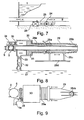
- Fig. 2 is shown the two spherical valves ( 5-A and 5-B ) that rotate in a uni-direction mode (the recoil nozzles are omitted for clarity ). It shows the horizontal Pelton turbine ( 14 ) with a vertical shaft coupled to the rotor of the main generator (15).
- Valve 5-A is in a fully opened position while the valve 5-B is in the fully closed position. Both valves have the same dimensions and are operated by motors that rotate continually.
- valve inner sphere having outlet or orifice that occupies one fourth of its circumference, as does the inlet orifice. In such a manner, it is at any time divided into four equal sections; two parts that would open up and two parts that would close the spherical valve down.
- the main penstock inside diameter is about one half the orifice diameter of the sphere.
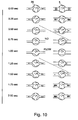
- valves are opened in one half second time interval ( Fig. 3-F to Fig. 3-H ) and stays open for the following one half second time interval ( Fig. 3-H to Fig. 3-I and Fig. 3-A to Fig. 3-B ). It closes in the next one half second time interval ( Fig. 3-B to Fig. 3-D ) and stays closed for the following one half second time interval ( Fig. 3-D to Fig. 3-F ).
- the two valve spheres have a frequency of one revolution per four seconds that make them 15 RPM valves. Their respective positions, i.e., opening and closing are timed to be one second apart as shown in Fig. 6 and Fig. 10 . In Fig. 2 , it shows that when valve 5-A is fully opened, valve 5-B is fully closed and vice-versa.
- Figs. 3-A to 3-I show the sequence of the spherical valve in its movements. At both sides of the sphere are two “ toy top “concaves. The concaves increase the surface area and torque of that section exposed to the increasing water hammer pressure as the valve closes and opens.
- Fig. 4 is the frontal view of the spherical valve showing the " toy top " depression on the sphere.
- the valve should be made of very strong steel material that would withstand the constant adverse dynamic forces of the water hammers.
- the rotor in the main generator ( 15 ) should possess enough mass that its moment of inertia ( M • R 2 ) is sufficiently increased to compensate for the pulsating jet energy mode. Therefore it needs to install flywheels. ( 16 )
- the pressure wave in this specific pipe with water temperature at 20 ° C is 1428.8 m/s.
- the rapid closure of the spherical valve rams up the energy head to 1,850 meters ( 1842 plus 8.17 ) high of pressure head.
- the spherical valve rotates to a fully opened position.
- the valve is fully opened releasing a high kinetic energy jet to impinge on the Pelton turbine-generator.
- the sphere rotates to close in the next 1/2 sec. time interval. This release of water jet is simultaneous with the abrupt decrease of pressure head in the penstock.
- Fig. 5 shows the projected chart of the water discharge.
- Fig. 5 charts this relationship.
- Hydrodynamic power Q W sp ⁇ H ave / 1000 ;
- This generated power is sustained by other natural forces, i.e., vacuum suction force ; the jet recoil force; gravitational force ; compressed air; inertia; and atmospheric air pressure PLUS the pressures from the auxiliary pump and the periodic re-boosting pump that are channeled into the system.
- vacuum suction force i.e., vacuum suction force ; the jet recoil force; gravitational force ; compressed air; inertia; and atmospheric air pressure PLUS the pressures from the auxiliary pump and the periodic re-boosting pump that are channeled into the system.
- the power required is 31.66 MW.
- the jet recoil force which is EQUAL and OPPOSITE in direction to the force of the released jet can be utilized to do different kinds of works.
- recoil force assembly is to use the uni-directional spherical valve ( 5 ) directly as the recoil assembly. Without the convergence nozzle, this assembly has all the above mentioned parts with the same functions, such as the pressure chamber; piston; spring; pressure pipe and its check valve; vacuum suction pipe and its check valve; air chamber; air relief orifice, steel column and guide rail.
- the water replenishment pipe (21) draws in water from the natural source nearby to replenish the loss of water due to evaporation. This is done by flowing water into the main reservoir of the system.
- the main reservoir ( 1 ) is of sufficient capacity to also serve as a cooling reservoir and is set up outside the powerhouse. It could be a natural body of water.
- the cooling system serves to cool the heated water that flow through the main penstock ( 9 ), the turbine, the transformer and other equipments. This system uses cooler atmospheric moving air as the main cooling agent.
- the heated water is carried out of the powerhouse together with the spent water in the tail reservoir through the outflow pipe ( 18 ) to the main reservoir that is exposed to the atmospheric air for dissipation.
- the temperature of the cooling reservoir has to be monitored to prevent it from getting too high. In case of high temperature, other cooling methods may be applied.
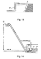
- the present invention has a second embodiment as shown in Fig. 14 wherein the force of pressure head provided by the main pump ( 6 ) in Fig. 11 is being substituted by the force of elevation head from an upper reservoir( 22 ) on top of a mountain plateau as shown in Fig. 14 ; the elevation head Z minus the down flow pipe frictional head loss is equal to the pressure head of the pump ; while the other equipments and structures of the second embodiment system are identical in dimensions and functions to the first embodiment system as presented.
- This second embodiment system has a motor pump ( 23 ) connected to the tail reservoir to deliver water from the lower level up to the upper reservoir ( 22 ) for re-circulation. It also has a low level reservoir similar to the main reservoir of the original embodiment outside the powerhouse to dissipate heat and to supply water to the vacuum suction pipes; auxiliary pump pipe line and re-boosting pipe line.
- the two embodiments of the present invention would have the same gross power output.
- the present invention is intended to be used as a base load generator.
- the excess capacity may be diverted to any other purposes within the powerhouse area, or we may opt to lower the rotating speed of the main motor pump ( 6 ), so as to decrease the velocity head in the main penstock ( 9 ), thus a lower water hammer pressure, producing subsequently a lower level of power.
- the present invention can be constructed as an independent power producing unit or it can be built as a sub-generation plant of an existing power plant.
Landscapes
- Engineering & Computer Science (AREA)
- Chemical & Material Sciences (AREA)
- Combustion & Propulsion (AREA)
- Mechanical Engineering (AREA)
- General Engineering & Computer Science (AREA)
- Dispersion Chemistry (AREA)
- Other Liquid Machine Or Engine Such As Wave Power Use (AREA)
- Jet Pumps And Other Pumps (AREA)
Applications Claiming Priority (1)
| Application Number | Priority Date | Filing Date | Title |
|---|---|---|---|
| CNA2007101959913A CN101311525A (zh) | 2007-12-14 | 2007-12-14 | 具有多样能源输入的水电系统 |
Publications (2)
| Publication Number | Publication Date |
|---|---|
| EP2071182A1 EP2071182A1 (en) | 2009-06-17 |
| EP2071182B1 true EP2071182B1 (en) | 2010-12-22 |
Family
ID=39111620
Family Applications (1)
| Application Number | Title | Priority Date | Filing Date |
|---|---|---|---|
| EP08002546A Not-in-force EP2071182B1 (en) | 2007-12-14 | 2008-02-12 | A multiple energy inputs hydropower system |
Country Status (12)
| Country | Link |
|---|---|
| US (1) | US20090152871A1 (pt) |
| EP (1) | EP2071182B1 (pt) |
| JP (1) | JP2009144721A (pt) |
| CN (1) | CN101311525A (pt) |
| AR (1) | AR069693A1 (pt) |
| AT (1) | ATE492724T1 (pt) |
| AU (1) | AU2008203487B2 (pt) |
| BR (1) | BRPI0804457A2 (pt) |
| DE (1) | DE602008004068D1 (pt) |
| ES (1) | ES2358622T3 (pt) |
| MX (1) | MX2008015952A (pt) |
| PT (1) | PT2071182E (pt) |
Cited By (1)
| Publication number | Priority date | Publication date | Assignee | Title |
|---|---|---|---|---|
| WO2020111953A1 (en) | 2018-11-27 | 2020-06-04 | Jose Ching | An atmospheric pressure powered electricity generation system |
Families Citing this family (49)
| Publication number | Priority date | Publication date | Assignee | Title |
|---|---|---|---|---|
| US8562833B2 (en) * | 2008-08-18 | 2013-10-22 | Clean And Green Enterprises, Inc. | Subsurface wave power generation water purification systems and methods |
| US20100186400A1 (en) * | 2009-01-26 | 2010-07-29 | Preston Robert B | Method, system and computer program product for producing renewable electrical power |
| BRMU8901223U2 (pt) * | 2009-06-16 | 2011-02-22 | Joao Batista Maglia | usina hidropneumoelétrica com casa de força cilìndrica imersa e plataforma terrestre |
| BRMU8901220U2 (pt) * | 2009-06-16 | 2011-02-22 | Joao Batista Maglia | usina hidropneumoelétrica com casa de força subterránea e plataforma terrestre |
| BRMU8901235U2 (pt) * | 2009-06-16 | 2011-02-22 | Joao Batista Maglia | usina hidropneumoelétrica com casa de força e depósito cilìndrico de água de superfìcie |
| US9739268B2 (en) * | 2009-12-21 | 2017-08-22 | Ronald Kurt Christensen | Transient liquid pressure power generation systems and associated devices and methods |
| US20110146275A1 (en) * | 2009-12-21 | 2011-06-23 | Ronald Kurt Christensen | High efficiency processes and inventions for producing continuing work from transient liquid pressures in a confined liquid |
| US9915179B2 (en) * | 2009-12-21 | 2018-03-13 | Ronald Kurt Christensen | Transient liquid pressure power generation systems and associated devices and methods |
| WO2012038983A2 (en) * | 2010-09-24 | 2012-03-29 | Sunil Gajanan Shinde | Apparatus for conserving water in a hydro power plant |
| CN102374103A (zh) * | 2011-05-17 | 2012-03-14 | 李光天 | 一种抽水蓄能自动循环供水做连续发电的水电站 |
| US20120297759A1 (en) * | 2011-05-27 | 2012-11-29 | Chui Wen Chiu | System of power generation with under water pressure of air |
| US20130038062A1 (en) | 2011-07-29 | 2013-02-14 | Samusideen Adewale Salu | System for producing hydraulic transient energy |
| CN102261563B (zh) * | 2011-08-08 | 2013-01-02 | 鲍云波 | 数控油水增压计量箱 |
| US20140197640A1 (en) * | 2013-01-16 | 2014-07-17 | Yaser K. Barakat | Hydroelectric power generating system |
| US9261068B2 (en) * | 2013-01-16 | 2016-02-16 | Yaser K. Barakat | Hydroelectric power generating system |
| US10001107B2 (en) | 2013-08-21 | 2018-06-19 | Paha Designs, Llc | Energy conversion system and method |
| GB201319832D0 (en) * | 2013-11-11 | 2013-12-25 | Eccles Peter G M | Hydro impulse engine |
| ITUB20153404A1 (it) * | 2015-09-07 | 2017-03-07 | Pezone Luigi Antonio | Elettropompe e turbine con doppia bocca di alimentazione |
| CN105221327B (zh) * | 2015-11-10 | 2018-01-05 | 内蒙古自治区水利水电勘测设计院 | 一种小型水力发电装置 |
| WO2018034624A1 (en) * | 2016-08-19 | 2018-02-22 | Sumritvanitcha Supot | Pumped storage turbine hydroelectric generating system |
| US11018554B2 (en) * | 2016-09-19 | 2021-05-25 | Frederick Forbes Vannan, Jr. | Method of generating hydro electric energy in rivers and streams without dams and/or locks |
| US10428786B2 (en) * | 2016-12-13 | 2019-10-01 | Richard M. Navarro | Hydroelectric turbine system |
| WO2018236808A1 (en) * | 2017-06-20 | 2018-12-27 | Jonathan Bannon Maher Corporation | GENERATOR & ENGINE GRAVITY |
| US11073139B2 (en) * | 2017-08-29 | 2021-07-27 | Mark R Anteau | Power generation system |
| US12092069B2 (en) | 2017-08-29 | 2024-09-17 | Mark R. Anteau | Power generator |
| CN107338773A (zh) * | 2017-08-30 | 2017-11-10 | 中国电建集团成都勘测设计研究院有限公司 | 用于水利水电工程的复合出水结构 |
| CN109139350B (zh) * | 2018-09-29 | 2024-01-26 | 东方电气自动控制工程有限公司 | 一种用于抽水蓄能电站的过速保护与流量控制装置 |
| CN109440870B (zh) * | 2018-12-29 | 2024-11-15 | 黄河勘测规划设计研究院有限公司 | 适于大型深埋长距离输水泵站用的水锤防护装置 |
| CN110259627B (zh) * | 2019-06-19 | 2024-02-27 | 浙江中新电力工程建设有限公司自动化分公司 | 基于电力物联网的电力施工安全管理系统 |
| CN110242479B (zh) * | 2019-06-19 | 2024-02-27 | 浙江中新电力工程建设有限公司自动化分公司 | 配电网支线接地故障定位系统 |
| CN110219288B (zh) * | 2019-07-12 | 2023-12-12 | 河南郑大水利科技有限公司 | 一种双阻抗式调压室 |
| ES2759174R1 (es) * | 2019-12-17 | 2020-05-19 | Olivan Angel Alonso | Central hidroeléctrica |
| PL243168B1 (pl) * | 2020-06-23 | 2023-07-10 | Zygmunt Nowak | Sposób wytwarzania energii elektrycznej oraz układ do wytwarzania energii elektrycznej, zwłaszcza elektrownia wodna |
| CN112651180B (zh) * | 2020-12-31 | 2022-06-14 | 昆明理工大学 | 一种一管多机水电机组调节系统微分方程计算方法 |
| KR102665075B1 (ko) * | 2021-01-13 | 2024-05-09 | 김진영 | 에너지 저장장치 |
| US11846263B2 (en) * | 2021-02-12 | 2023-12-19 | Hector Eduardo Medina | Hybrid renewable pumped storage hydropower energy storage system |
| CN113153611A (zh) * | 2021-04-30 | 2021-07-23 | 旺苍县科美防震科技有限公司 | 一种密封式节能河道水能发电站 |
| US11920720B2 (en) | 2021-05-14 | 2024-03-05 | Saudi Arabian Oil Company | System and method for mitigating water hammer by looping surge pressure |
| US11852116B2 (en) * | 2021-05-21 | 2023-12-26 | Trevor Brown | Water tower-based apparatuses and methods |
| US12180919B2 (en) * | 2021-12-03 | 2024-12-31 | Power8 Tech. Inc. | Power tunnel |
| KR102794376B1 (ko) * | 2021-12-03 | 2025-04-09 | 파워8 테크 인코포레이티드 | 이종 압력 매체 및 양방향 작동 모듈을 사용한 에너지 저장 시스템 및 방법 |
| US12234797B2 (en) * | 2021-12-03 | 2025-02-25 | Powers8 TECH INC. | Smart controlling systems for energy storage |
| US12253285B2 (en) * | 2021-12-03 | 2025-03-18 | Power8 Tech. Inc. | Geothermal energy storage and conversion systems and methods |
| US12355238B2 (en) * | 2021-12-03 | 2025-07-08 | Power8 Tech. Inc. | Energy storage systems and methods using heterogeneous pressure media and interactive actuation module |
| US20250075677A1 (en) * | 2022-08-23 | 2025-03-06 | ParseHill Renwables, LLC | Power generation from moving water |
| TW202424404A (zh) | 2022-09-13 | 2024-06-16 | 美商能源8科技公司 | 聚光太陽能儲存系統及方法 |
| US20240200526A1 (en) * | 2022-12-14 | 2024-06-20 | Edward T. Tirpak | Device and methods for converting hydraulic drag force into rotational force |
| UA154165U (uk) * | 2023-03-08 | 2023-10-18 | Валерій Михайлович Орлов | Гідроударна електростанція з автономною напірною насосною станцією водопостачання |
| CN117230762B (zh) * | 2023-10-25 | 2026-04-07 | 西藏电建成勘院工程有限公司 | 双室式调压室结构 |
Family Cites Families (14)
| Publication number | Priority date | Publication date | Assignee | Title |
|---|---|---|---|---|
| US1898337A (en) * | 1929-09-03 | 1933-02-21 | Robert A Brooks | Water compression system |
| US3137316A (en) * | 1962-05-17 | 1964-06-16 | Wilhelm S Everett | Fluid pulsation dampener |
| US3942549A (en) * | 1974-06-17 | 1976-03-09 | Morris Tobin | Water hammer arrestor |
| US4220003A (en) * | 1979-03-30 | 1980-09-02 | Kiyoshi Doi | Apparatus for generating rotational power |
| JPS57181976A (en) * | 1981-05-01 | 1982-11-09 | Hiroshi Ochiai | Hydraulic generator |
| JPS5958167A (ja) * | 1982-09-28 | 1984-04-03 | Masatoshi Toyoda | 比重応用による簡易全自動発電装置 |
| KR930003056B1 (ko) * | 1987-07-24 | 1993-04-17 | 가부시기 가이샤 이낙스 | 수격흡수기 |
| US4965998A (en) * | 1989-02-21 | 1990-10-30 | Estigoy Filemon E | Mini hydro electric plant |
| US6338342B1 (en) * | 1999-02-22 | 2002-01-15 | Cabot Safety Intermediate Corporation | Respirator headpiece and release mechanism |
| US6420794B1 (en) * | 2000-06-23 | 2002-07-16 | Thanh D. Cao | Hydropower conversion system |
| USD471960S1 (en) * | 2002-01-22 | 2003-03-18 | Ips Corporation | Combination valve and water hammer arrester |
| WO2004094816A1 (en) * | 2003-04-22 | 2004-11-04 | Assad Beshara Assad | Plant for generation of electricity from force of gravity |
| WO2006085782A1 (en) | 2005-07-26 | 2006-08-17 | Jose Ching | Re-circulating water in close-looped hydropower system |
| DE102006019008A1 (de) * | 2006-04-25 | 2007-10-31 | Johann Buchta | Wasserkraftwerk mit verstärkter elektrischer Leistung |
-
2007
- 2007-12-14 CN CNA2007101959913A patent/CN101311525A/zh active Pending
-
2008
- 2008-02-12 PT PT08002546T patent/PT2071182E/pt unknown
- 2008-02-12 ES ES08002546T patent/ES2358622T3/es active Active
- 2008-02-12 AT AT08002546T patent/ATE492724T1/de active
- 2008-02-12 DE DE602008004068T patent/DE602008004068D1/de active Active
- 2008-02-12 EP EP08002546A patent/EP2071182B1/en not_active Not-in-force
- 2008-04-17 US US12/081,528 patent/US20090152871A1/en not_active Abandoned
- 2008-07-31 BR BRPI0804457-0A patent/BRPI0804457A2/pt not_active IP Right Cessation
- 2008-08-04 AU AU2008203487A patent/AU2008203487B2/en not_active Ceased
- 2008-12-12 AR ARP080105432A patent/AR069693A1/es not_active Application Discontinuation
- 2008-12-12 JP JP2008316474A patent/JP2009144721A/ja active Pending
- 2008-12-12 MX MX2008015952A patent/MX2008015952A/es active IP Right Grant
Cited By (1)
| Publication number | Priority date | Publication date | Assignee | Title |
|---|---|---|---|---|
| WO2020111953A1 (en) | 2018-11-27 | 2020-06-04 | Jose Ching | An atmospheric pressure powered electricity generation system |
Also Published As
| Publication number | Publication date |
|---|---|
| AU2008203487A1 (en) | 2009-07-02 |
| AU2008203487B2 (en) | 2011-06-09 |
| ATE492724T1 (de) | 2011-01-15 |
| MX2008015952A (es) | 2009-06-18 |
| JP2009144721A (ja) | 2009-07-02 |
| AR069693A1 (es) | 2010-02-10 |
| ES2358622T3 (es) | 2011-05-12 |
| PT2071182E (pt) | 2011-01-24 |
| BRPI0804457A2 (pt) | 2009-08-25 |
| CN101311525A (zh) | 2008-11-26 |
| US20090152871A1 (en) | 2009-06-18 |
| DE602008004068D1 (de) | 2011-02-03 |
| EP2071182A1 (en) | 2009-06-17 |
Similar Documents
| Publication | Publication Date | Title |
|---|---|---|
| EP2071182B1 (en) | A multiple energy inputs hydropower system | |
| JP2009144721A5 (pt) | ||
| US6546723B1 (en) | Hydropower conversion system | |
| US8839615B2 (en) | Power conversion | |
| CN105408622B (zh) | 水下水力发电机设备和将水从这样的设备排出的方法 | |
| US20120167563A1 (en) | Advanced high energy wave power module | |
| US20140217737A1 (en) | Wave-power electricity generation system | |
| EP2449252A2 (en) | Low-drag hydro-pneumatic power cylinder and system | |
| US20110204642A1 (en) | River High Pressure Energy Conversion Machine | |
| US12331710B2 (en) | Power amplification, storage and regeneration system and method using tides, waves and/or wind | |
| WO2020215118A1 (en) | Tidal power harnessing, storage and regeneration system and method | |
| EP4119789B1 (en) | River venturi power amplification, storage and regeneration system | |
| RU2629350C1 (ru) | Гидроаккумулирующая система | |
| EP1869316A1 (en) | Re-circulating water in close-looped hydropower system | |
| Singal | Hydraulic Machines: Fluid Machinery | |
| EP2302202A1 (en) | Hydraulic propulsion for increases of hydroelektric power station capacity | |
| CN115653837A (zh) | 一种风力发电深海储能装置及动态调控方法 | |
| Gorlov | Hydrogen as an activating fuel for a tidal power plant | |
| RU2849228C1 (ru) | Энергетическая установка | |
| HK1125685A (en) | A hydropower system with multiple energy inputs | |
| RU2551145C1 (ru) | Способ получения энергии ветра и преобразования её в другие виды энергии и ветроэнергетическое устройство для его осуществления | |
| CN110454311A (zh) | 一种履带式水轮机 | |
| JP7683015B2 (ja) | エアハイドロパワーから電気エネルギーを生成するための改良版システムおよび方法 | |
| RU197758U1 (ru) | Устройство рекуперации избыточного давления теплоносителя | |
| WO2012026701A2 (ko) | 에너지 효율을 향상시키는 발전장치 |
Legal Events
| Date | Code | Title | Description |
|---|---|---|---|
| PUAI | Public reference made under article 153(3) epc to a published international application that has entered the european phase |
Free format text: ORIGINAL CODE: 0009012 |
|
| 17P | Request for examination filed |
Effective date: 20080825 |
|
| AK | Designated contracting states |
Kind code of ref document: A1 Designated state(s): AT BE BG CH CY CZ DE DK EE ES FI FR GB GR HR HU IE IS IT LI LT LU LV MC MT NL NO PL PT RO SE SI SK TR |
|
| AX | Request for extension of the european patent |
Extension state: AL BA MK RS |
|
| AKX | Designation fees paid |
Designated state(s): AT BE BG CH CY CZ DE DK EE ES FI FR GB GR HR HU IE IS IT LI LT LU LV MC MT NL NO PL PT RO SE SI SK TR |
|
| 17Q | First examination report despatched |
Effective date: 20100201 |
|
| GRAP | Despatch of communication of intention to grant a patent |
Free format text: ORIGINAL CODE: EPIDOSNIGR1 |
|
| GRAS | Grant fee paid |
Free format text: ORIGINAL CODE: EPIDOSNIGR3 |
|
| GRAA | (expected) grant |
Free format text: ORIGINAL CODE: 0009210 |
|
| AK | Designated contracting states |
Kind code of ref document: B1 Designated state(s): AT BE BG CH CY CZ DE DK EE ES FI FR GB GR HR HU IE IS IT LI LT LU LV MC MT NL NO PL PT RO SE SI SK TR |
|
| REG | Reference to a national code |
Ref country code: GB Ref legal event code: FG4D |
|
| REG | Reference to a national code |
Ref country code: CH Ref legal event code: NV Representative=s name: HEPP WENGER RYFFEL AG Ref country code: CH Ref legal event code: EP |
|
| REG | Reference to a national code |
Ref country code: IE Ref legal event code: FG4D |
|
| REG | Reference to a national code |
Ref country code: PT Ref legal event code: SC4A Free format text: AVAILABILITY OF NATIONAL TRANSLATION Effective date: 20110117 |
|
| REF | Corresponds to: |
Ref document number: 602008004068 Country of ref document: DE Date of ref document: 20110203 Kind code of ref document: P |
|
| REG | Reference to a national code |
Ref country code: DE Ref legal event code: R096 Ref document number: 602008004068 Country of ref document: DE Effective date: 20110203 |
|
| REG | Reference to a national code |
Ref country code: NL Ref legal event code: VDEP Effective date: 20101222 |
|
| PG25 | Lapsed in a contracting state [announced via postgrant information from national office to epo] |
Ref country code: LT Free format text: LAPSE BECAUSE OF FAILURE TO SUBMIT A TRANSLATION OF THE DESCRIPTION OR TO PAY THE FEE WITHIN THE PRESCRIBED TIME-LIMIT Effective date: 20101222 |
|
| REG | Reference to a national code |
Ref country code: ES Ref legal event code: FG2A Ref document number: 2358622 Country of ref document: ES Kind code of ref document: T3 Effective date: 20110429 |
|
| LTIE | Lt: invalidation of european patent or patent extension |
Effective date: 20101222 |
|
| PG25 | Lapsed in a contracting state [announced via postgrant information from national office to epo] |
Ref country code: CY Free format text: LAPSE BECAUSE OF FAILURE TO SUBMIT A TRANSLATION OF THE DESCRIPTION OR TO PAY THE FEE WITHIN THE PRESCRIBED TIME-LIMIT Effective date: 20101222 Ref country code: BG Free format text: LAPSE BECAUSE OF FAILURE TO SUBMIT A TRANSLATION OF THE DESCRIPTION OR TO PAY THE FEE WITHIN THE PRESCRIBED TIME-LIMIT Effective date: 20110322 Ref country code: FI Free format text: LAPSE BECAUSE OF FAILURE TO SUBMIT A TRANSLATION OF THE DESCRIPTION OR TO PAY THE FEE WITHIN THE PRESCRIBED TIME-LIMIT Effective date: 20101222 Ref country code: SI Free format text: LAPSE BECAUSE OF FAILURE TO SUBMIT A TRANSLATION OF THE DESCRIPTION OR TO PAY THE FEE WITHIN THE PRESCRIBED TIME-LIMIT Effective date: 20101222 Ref country code: SE Free format text: LAPSE BECAUSE OF FAILURE TO SUBMIT A TRANSLATION OF THE DESCRIPTION OR TO PAY THE FEE WITHIN THE PRESCRIBED TIME-LIMIT Effective date: 20101222 Ref country code: LV Free format text: LAPSE BECAUSE OF FAILURE TO SUBMIT A TRANSLATION OF THE DESCRIPTION OR TO PAY THE FEE WITHIN THE PRESCRIBED TIME-LIMIT Effective date: 20101222 Ref country code: HR Free format text: LAPSE BECAUSE OF FAILURE TO SUBMIT A TRANSLATION OF THE DESCRIPTION OR TO PAY THE FEE WITHIN THE PRESCRIBED TIME-LIMIT Effective date: 20101222 |
|
| PG25 | Lapsed in a contracting state [announced via postgrant information from national office to epo] |
Ref country code: CZ Free format text: LAPSE BECAUSE OF FAILURE TO SUBMIT A TRANSLATION OF THE DESCRIPTION OR TO PAY THE FEE WITHIN THE PRESCRIBED TIME-LIMIT Effective date: 20101222 Ref country code: IS Free format text: LAPSE BECAUSE OF FAILURE TO SUBMIT A TRANSLATION OF THE DESCRIPTION OR TO PAY THE FEE WITHIN THE PRESCRIBED TIME-LIMIT Effective date: 20110422 Ref country code: NO Free format text: LAPSE BECAUSE OF FAILURE TO SUBMIT A TRANSLATION OF THE DESCRIPTION OR TO PAY THE FEE WITHIN THE PRESCRIBED TIME-LIMIT Effective date: 20110322 Ref country code: GR Free format text: LAPSE BECAUSE OF FAILURE TO SUBMIT A TRANSLATION OF THE DESCRIPTION OR TO PAY THE FEE WITHIN THE PRESCRIBED TIME-LIMIT Effective date: 20110323 Ref country code: EE Free format text: LAPSE BECAUSE OF FAILURE TO SUBMIT A TRANSLATION OF THE DESCRIPTION OR TO PAY THE FEE WITHIN THE PRESCRIBED TIME-LIMIT Effective date: 20101222 |
|
| PG25 | Lapsed in a contracting state [announced via postgrant information from national office to epo] |
Ref country code: RO Free format text: LAPSE BECAUSE OF FAILURE TO SUBMIT A TRANSLATION OF THE DESCRIPTION OR TO PAY THE FEE WITHIN THE PRESCRIBED TIME-LIMIT Effective date: 20101222 Ref country code: SK Free format text: LAPSE BECAUSE OF FAILURE TO SUBMIT A TRANSLATION OF THE DESCRIPTION OR TO PAY THE FEE WITHIN THE PRESCRIBED TIME-LIMIT Effective date: 20101222 Ref country code: NL Free format text: LAPSE BECAUSE OF FAILURE TO SUBMIT A TRANSLATION OF THE DESCRIPTION OR TO PAY THE FEE WITHIN THE PRESCRIBED TIME-LIMIT Effective date: 20101222 Ref country code: PL Free format text: LAPSE BECAUSE OF FAILURE TO SUBMIT A TRANSLATION OF THE DESCRIPTION OR TO PAY THE FEE WITHIN THE PRESCRIBED TIME-LIMIT Effective date: 20101222 |
|
| PG25 | Lapsed in a contracting state [announced via postgrant information from national office to epo] |
Ref country code: MC Free format text: LAPSE BECAUSE OF NON-PAYMENT OF DUE FEES Effective date: 20110228 |
|
| PLBE | No opposition filed within time limit |
Free format text: ORIGINAL CODE: 0009261 |
|
| STAA | Information on the status of an ep patent application or granted ep patent |
Free format text: STATUS: NO OPPOSITION FILED WITHIN TIME LIMIT |
|
| PG25 | Lapsed in a contracting state [announced via postgrant information from national office to epo] |
Ref country code: DK Free format text: LAPSE BECAUSE OF FAILURE TO SUBMIT A TRANSLATION OF THE DESCRIPTION OR TO PAY THE FEE WITHIN THE PRESCRIBED TIME-LIMIT Effective date: 20101222 |
|
| 26N | No opposition filed |
Effective date: 20110923 |
|
| PG25 | Lapsed in a contracting state [announced via postgrant information from national office to epo] |
Ref country code: MT Free format text: LAPSE BECAUSE OF FAILURE TO SUBMIT A TRANSLATION OF THE DESCRIPTION OR TO PAY THE FEE WITHIN THE PRESCRIBED TIME-LIMIT Effective date: 20101222 |
|
| REG | Reference to a national code |
Ref country code: DE Ref legal event code: R097 Ref document number: 602008004068 Country of ref document: DE Effective date: 20110923 |
|
| PGFP | Annual fee paid to national office [announced via postgrant information from national office to epo] |
Ref country code: IE Payment date: 20120217 Year of fee payment: 5 Ref country code: CH Payment date: 20120221 Year of fee payment: 5 |
|
| PGFP | Annual fee paid to national office [announced via postgrant information from national office to epo] |
Ref country code: PT Payment date: 20120202 Year of fee payment: 5 |
|
| PGFP | Annual fee paid to national office [announced via postgrant information from national office to epo] |
Ref country code: BE Payment date: 20120221 Year of fee payment: 5 Ref country code: IT Payment date: 20120223 Year of fee payment: 5 |
|
| PGFP | Annual fee paid to national office [announced via postgrant information from national office to epo] |
Ref country code: FR Payment date: 20130315 Year of fee payment: 6 |
|
| PG25 | Lapsed in a contracting state [announced via postgrant information from national office to epo] |
Ref country code: LU Free format text: LAPSE BECAUSE OF NON-PAYMENT OF DUE FEES Effective date: 20110212 |
|
| PGFP | Annual fee paid to national office [announced via postgrant information from national office to epo] |
Ref country code: ES Payment date: 20120221 Year of fee payment: 5 |
|
| REG | Reference to a national code |
Ref country code: PT Ref legal event code: MM4A Free format text: LAPSE DUE TO NON-PAYMENT OF FEES Effective date: 20130812 |
|
| BERE | Be: lapsed |
Owner name: CHING, JOSE Effective date: 20130228 |
|
| PG25 | Lapsed in a contracting state [announced via postgrant information from national office to epo] |
Ref country code: TR Free format text: LAPSE BECAUSE OF FAILURE TO SUBMIT A TRANSLATION OF THE DESCRIPTION OR TO PAY THE FEE WITHIN THE PRESCRIBED TIME-LIMIT Effective date: 20101222 |
|
| REG | Reference to a national code |
Ref country code: CH Ref legal event code: PL |
|
| PG25 | Lapsed in a contracting state [announced via postgrant information from national office to epo] |
Ref country code: CH Free format text: LAPSE BECAUSE OF NON-PAYMENT OF DUE FEES Effective date: 20130228 Ref country code: HU Free format text: LAPSE BECAUSE OF FAILURE TO SUBMIT A TRANSLATION OF THE DESCRIPTION OR TO PAY THE FEE WITHIN THE PRESCRIBED TIME-LIMIT Effective date: 20101222 Ref country code: PT Free format text: LAPSE BECAUSE OF NON-PAYMENT OF DUE FEES Effective date: 20130812 Ref country code: LI Free format text: LAPSE BECAUSE OF NON-PAYMENT OF DUE FEES Effective date: 20130228 |
|
| REG | Reference to a national code |
Ref country code: IE Ref legal event code: MM4A |
|
| PG25 | Lapsed in a contracting state [announced via postgrant information from national office to epo] |
Ref country code: IT Free format text: LAPSE BECAUSE OF NON-PAYMENT OF DUE FEES Effective date: 20130212 |
|
| PG25 | Lapsed in a contracting state [announced via postgrant information from national office to epo] |
Ref country code: IE Free format text: LAPSE BECAUSE OF NON-PAYMENT OF DUE FEES Effective date: 20130212 Ref country code: BE Free format text: LAPSE BECAUSE OF NON-PAYMENT OF DUE FEES Effective date: 20130228 |
|
| REG | Reference to a national code |
Ref country code: AT Ref legal event code: MM01 Ref document number: 492724 Country of ref document: AT Kind code of ref document: T Effective date: 20130212 |
|
| PG25 | Lapsed in a contracting state [announced via postgrant information from national office to epo] |
Ref country code: AT Free format text: LAPSE BECAUSE OF NON-PAYMENT OF DUE FEES Effective date: 20130212 |
|
| REG | Reference to a national code |
Ref country code: ES Ref legal event code: FD2A Effective date: 20140606 |
|
| PG25 | Lapsed in a contracting state [announced via postgrant information from national office to epo] |
Ref country code: ES Free format text: LAPSE BECAUSE OF NON-PAYMENT OF DUE FEES Effective date: 20130213 |
|
| REG | Reference to a national code |
Ref country code: FR Ref legal event code: ST Effective date: 20141031 |
|
| PG25 | Lapsed in a contracting state [announced via postgrant information from national office to epo] |
Ref country code: FR Free format text: LAPSE BECAUSE OF NON-PAYMENT OF DUE FEES Effective date: 20140228 |
|
| PGFP | Annual fee paid to national office [announced via postgrant information from national office to epo] |
Ref country code: DE Payment date: 20150226 Year of fee payment: 8 |
|
| PGFP | Annual fee paid to national office [announced via postgrant information from national office to epo] |
Ref country code: GB Payment date: 20150223 Year of fee payment: 8 |
|
| REG | Reference to a national code |
Ref country code: DE Ref legal event code: R119 Ref document number: 602008004068 Country of ref document: DE |
|
| GBPC | Gb: european patent ceased through non-payment of renewal fee |
Effective date: 20160212 |
|
| PG25 | Lapsed in a contracting state [announced via postgrant information from national office to epo] |
Ref country code: GB Free format text: LAPSE BECAUSE OF NON-PAYMENT OF DUE FEES Effective date: 20160212 Ref country code: DE Free format text: LAPSE BECAUSE OF NON-PAYMENT OF DUE FEES Effective date: 20160901 |