EP2071201A1 - Vis à cisaillement - Google Patents
Vis à cisaillement Download PDFInfo
- Publication number
- EP2071201A1 EP2071201A1 EP07291494A EP07291494A EP2071201A1 EP 2071201 A1 EP2071201 A1 EP 2071201A1 EP 07291494 A EP07291494 A EP 07291494A EP 07291494 A EP07291494 A EP 07291494A EP 2071201 A1 EP2071201 A1 EP 2071201A1
- Authority
- EP
- European Patent Office
- Prior art keywords
- blind hole
- predetermined breaking
- screw
- shear screw
- section
- Prior art date
- Legal status (The legal status is an assumption and is not a legal conclusion. Google has not performed a legal analysis and makes no representation as to the accuracy of the status listed.)
- Granted
Links
Images


Classifications
-
- F—MECHANICAL ENGINEERING; LIGHTING; HEATING; WEAPONS; BLASTING
- F16—ENGINEERING ELEMENTS AND UNITS; GENERAL MEASURES FOR PRODUCING AND MAINTAINING EFFECTIVE FUNCTIONING OF MACHINES OR INSTALLATIONS; THERMAL INSULATION IN GENERAL
- F16B—DEVICES FOR FASTENING OR SECURING CONSTRUCTIONAL ELEMENTS OR MACHINE PARTS TOGETHER, e.g. NAILS, BOLTS, CIRCLIPS, CLAMPS, CLIPS OR WEDGES; JOINTS OR JOINTING
- F16B31/00—Screwed connections specially modified in view of tensile load; Break-bolts
- F16B31/02—Screwed connections specially modified in view of tensile load; Break-bolts for indicating the attainment of a particular tensile load or limiting tensile load
- F16B31/021—Screwed connections specially modified in view of tensile load; Break-bolts for indicating the attainment of a particular tensile load or limiting tensile load by means of a frangible part
-
- H—ELECTRICITY
- H01—ELECTRIC ELEMENTS
- H01R—ELECTRICALLY-CONDUCTIVE CONNECTIONS; STRUCTURAL ASSOCIATIONS OF A PLURALITY OF MUTUALLY-INSULATED ELECTRICAL CONNECTING ELEMENTS; COUPLING DEVICES; CURRENT COLLECTORS
- H01R4/00—Electrically-conductive connections between two or more conductive members in direct contact, i.e. touching one another; Means for effecting or maintaining such contact; Electrically-conductive connections having two or more spaced connecting locations for conductors and using contact members penetrating insulation
- H01R4/28—Clamped connections, spring connections
- H01R4/30—Clamped connections, spring connections utilising a screw or nut clamping member
- H01R4/36—Conductive members located under tip of screw
- H01R4/363—Conductive members located under tip of screw with intermediate part between tip and conductive member
Definitions
- the invention relates to a shear screw for fastening an electrical conductor in a metallic clamp designed as a pipe piece, which has in its wall at least one threaded through hole for receiving the shear screw, which has predetermined breaking points in two axially separate planes, a first predetermined breaking point and a second predetermined breaking point, and having a centrally extending over a substantial length blind hole having a cross section suitable for transmitting a torque to the shear screw by means of a plugged into the blind hole, pin-like tool whose cross section of the cross section of the blind hole and its outer dimensions correspond to the clear dimensions of the same ( EP 0 750 723 B1 ).
- a suitable for transmitting a torque cross-sectional shape of the blind hole and tool is in particular a polygonal cross section to understand, with advantage a hexagon.
- suitable cross-sectional shapes are stars, which may also have rounded tips and corners, or even in the shear screw mounted simple slots and Phillips with appropriate, shaped as a flat profile and cross tool.
- the polygonal cross-section is taken into account as representative of all possible cross-sectional shapes.
- Such a shear screw - hereinafter referred to as "screw" - is used, for example, in power engineering for connecting the conductors of two power cables.
- screw screw
- a fixed connection between the conductors of two cables and a tubular metallic clamp is required, in which the conductors are inserted.
- torque wrench which when tightening the screw then "twisted” when a sufficient tight fit of the same is reached.
- torque wrench is often not available on a construction site. The screw is therefore usually tightened with another tool, for example with a simple wrench.
- the upper part of the screw is sheared off when the strength of its predetermined breaking point is reached or exceeded.
- the then missing screw head is an indication that the screw is sufficiently tightened.
- the screw protrudes after shearing off the screw head not or only slightly out of the clamp out.
- An insulating element to be mounted above the same is therefore neither mechanically damaged nor impaired in its insulating properties.
- the well-known screw according to the above-mentioned EP 0 750 723 B1 has a plurality of axially spaced predetermined breaking points. Depending on its depth of penetration, it is sheared off at one of the predetermined breaking points in a cable connector designed as a metallic pipe section, which depends on the dimensions of a conductor to be defined.
- An initially completely inserted into a blind hole of the screw pin of a tool is to be moved by a screwing by means of an outer bell-shaped support means, which is part of the tool and rests on the cable connector, gradually relative to the screw out of the same.
- the screw is sheared off at a predetermined breaking point, which is approximately at the level of the end face of the pin of the tool in the position in which the screwing is completed.
- the tool is a total of consuming.
- the invention has for its object to make the initially described screw so that it can be brought in a simpler way for fixed contact with a ladder.
- This screw is designed so that it can be rotated with a simple, pin-like tool in the threaded hole of a clamp until a conductor to be fixed in the same is set with sufficient pressure.
- Their two predetermined breaking points have different strength, so that the screw is sheared off first or only in a first working position at the first predetermined breaking point with the lower strength. In this first working position, for example, a thinner conductor of a cable is fixed in the clamp. After shearing off the head of the screw at the first predetermined breaking point, it can be brought, as required, into a second working position provided, for example, to define a thicker conductor, with the same simple tool in which it is sheared off at the second predetermined breaking point.
- shear screw S - hereinafter referred to as "screw S" - has a threaded portion 1 and a head 2, which has smaller radial dimensions than the threaded portion 1 in the illustrated embodiment and is designed without external thread.
- the threaded part 1 ends at the end face 3 of the screw S.
- the transition from the head 2 to the threaded part 1 is tapered conically all around.
- the point with the smallest diameter forms a first predetermined breaking point 4 of the screw S.
- a circumferential, gap-like depression is also attached, which forms a second predetermined breaking point 5 of the screw S.
- the strength of the second predetermined breaking point 5 is greater than that of the first predetermined breaking point.
- the two predetermined breaking points 4 and 5 run in the embodiment of the screw S after Fig. 1 perpendicular to the axis of the screw S and parallel to each other.
- a blind hole 6 is mounted with a polygonal cross-section which extends from the end face of the head 2 to the level of the second predetermined breaking point 5.
- the blind hole 6 preferably has a hexagonal cross section, as in the FIGS. 2 and 3 is shown. It can also have a different polygonal cross-section.
- Concentric with the blind hole 6 in the screw S a cross-sectionally also polygonal recess 7 is mounted, which is axially shorter than the blind hole 6 and extends to the level of the first predetermined breaking point 4.
- the recess 7 has the same cross-section and the same clear dimensions as the blind hole 6. So it is also carried out with advantage hexagonal.
- the recess 7 is offset relative to the blind hole 6 in the circumferential direction, for example at an angle of 30 °, as it is in Fig. 2 is drawn. This angle should preferably be between 10 ° and 40 °, with advantage at 20 °.
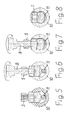
- the blind hole 6 is so deformed at its entrance into the screw S, that is, at the end face of the head 2, that an example in Fig. 6 drawn pin-like tool 8 can not be inserted into the same.
- the tool 8 is used to rotate the screw S. It has a polygonal cross section, which corresponds to the cross section of the blind hole 6 and recess 7. Its outer dimensions correspond to the clear dimensions of blind hole 6 and recess 7.
- the blind hole 6 has as deformation according to Fig. 2 For example, at three points 9 small projections that protrude into his profile and serve as a stopper for the tool 8. Basically, such a stopper is sufficient at only one point 9.
- the recess 7 is unchanged in cross section in the end face on the head 2 of the screw, so that the tool 8 can be inserted freely in the same.
- an electrical conductor 11 is to be set with relatively small dimensions with a predetermined pressure.
- the screw S is screwed into a threaded bore of the terminal 10, until it according to Fig. 5 at the previously inserted in the same, head 11 is applied.
- this can also be done by hand using the tool 8.
- the tool 8 is in the position after Fig. 6 inserted into the recess 7. Its end face is then equal to the first predetermined breaking point 4.
- the tool 8 By rotation of the tool 8 about the axis of the screw S, it is further screwed into the clamp 10, whereby the conductor 10 is compressed.
- the conductor 10 In the in Fig. 7 shown position of the screw S, the conductor 10 is loaded with sufficient pressure.
- the head 2 of the screw S is then sheared off. It remains in accordance Fig. 8 the threaded part 1 in the terminal 10, without projection
- the same procedure applies initially for the determination of a thicker conductor 12 in the terminal 10.
- the screw S is in accordance with Fig. 9 initially screwed again to the plant on the conductor 12 in the terminal 10 and then further rotated by means of the tool 8 ( Fig. 10 ), whereby the conductor 12 is deformed.
- the counterforce of the conductor 12 is then so high that the head 2 of the screw S is sheared off at the weaker first predetermined breaking point 4, before a sufficiently high pressure on the conductor 12 is applied.
- This position of the remaining threaded part 1 of the screw S is in Fig. 11 shown.
- the tool 8 is now inserted into the part of the blind hole 6 present in the threaded part 1.
- the threaded part 1 of the screw S is then further rotated until the pressure to be exerted on the conductor 12 is reached ( Fig. 12 ).
- the upper part of the threaded part 1 of the screw S is then sheared off at the second predetermined breaking point 5.
- the lower part of the threaded part 1 remains according to Fig. 13 in terminal 10, again without supernatant.
- the stripped conductor of a second cable is fixed in a similar manner by means of a screw S in conventional technology at the other end of the terminal 10. Finally, an insulating element can be formed around the clamp 10.
- the predetermined breaking points 4 and 5 of the screw S run according to the embodiment of the same after Fig. 1 perpendicular to the axis of the screw S and parallel to each other. You can according to Fig. 4 Also run obliquely to the axis of the screw S, preferably with the opposite direction of the bevels. Their directions then include an acute angle of, for example, 30 ° with each other.
- the predetermined breaking point 5 ends closer to the end face 3 thereof, so that the blind hole 6 with respect to the embodiment according to FIG Fig. 1 can be extended.
- the tool 8 can thereby be inserted deeper into the screw S and it can be a correspondingly larger moment transmitted to the predetermined breaking point 5.
Landscapes
- Engineering & Computer Science (AREA)
- General Engineering & Computer Science (AREA)
- Mechanical Engineering (AREA)
- Connections By Means Of Piercing Elements, Nuts, Or Screws (AREA)
- Clamps And Clips (AREA)
- Installation Of Indoor Wiring (AREA)
- Mechanical Treatment Of Semiconductor (AREA)
- Separation By Low-Temperature Treatments (AREA)
- Compression-Type Refrigeration Machines With Reversible Cycles (AREA)
- Connections Effected By Soldering, Adhesion, Or Permanent Deformation (AREA)
- Hand Tools For Fitting Together And Separating, Or Other Hand Tools (AREA)
- Dowels (AREA)
Priority Applications (7)
| Application Number | Priority Date | Filing Date | Title |
|---|---|---|---|
| ES07291494T ES2341135T3 (es) | 2007-12-11 | 2007-12-11 | Tornillo con cizalladura. |
| DE502007003243T DE502007003243D1 (de) | 2007-12-11 | 2007-12-11 | Abscherschraube |
| DK07291494.8T DK2071201T3 (da) | 2007-12-11 | 2007-12-11 | Afklipningsskrue |
| AT07291494T ATE462084T1 (de) | 2007-12-11 | 2007-12-11 | Abscherschraube |
| EP07291494A EP2071201B1 (fr) | 2007-12-11 | 2007-12-11 | Vis à cisaillement |
| US12/313,152 US8317443B2 (en) | 2007-12-11 | 2008-11-17 | Shear screw |
| CN2008101908920A CN101487486B (zh) | 2007-12-11 | 2008-12-11 | 剪切螺丝 |
Applications Claiming Priority (1)
| Application Number | Priority Date | Filing Date | Title |
|---|---|---|---|
| EP07291494A EP2071201B1 (fr) | 2007-12-11 | 2007-12-11 | Vis à cisaillement |
Publications (2)
| Publication Number | Publication Date |
|---|---|
| EP2071201A1 true EP2071201A1 (fr) | 2009-06-17 |
| EP2071201B1 EP2071201B1 (fr) | 2010-03-24 |
Family
ID=39327379
Family Applications (1)
| Application Number | Title | Priority Date | Filing Date |
|---|---|---|---|
| EP07291494A Active EP2071201B1 (fr) | 2007-12-11 | 2007-12-11 | Vis à cisaillement |
Country Status (7)
| Country | Link |
|---|---|
| US (1) | US8317443B2 (fr) |
| EP (1) | EP2071201B1 (fr) |
| CN (1) | CN101487486B (fr) |
| AT (1) | ATE462084T1 (fr) |
| DE (1) | DE502007003243D1 (fr) |
| DK (1) | DK2071201T3 (fr) |
| ES (1) | ES2341135T3 (fr) |
Cited By (8)
| Publication number | Priority date | Publication date | Assignee | Title |
|---|---|---|---|---|
| EP2322816A1 (fr) * | 2009-11-17 | 2011-05-18 | Nexans | Vis de serrage |
| EP2400594A3 (fr) * | 2010-06-24 | 2012-02-22 | Cable Accessories (Australia) PTY., Ltd. | Système de connexion de câble |
| EP2487755A1 (fr) * | 2011-02-08 | 2012-08-15 | Nexans | Vis de serrage |
| US8905880B2 (en) | 2012-08-06 | 2014-12-09 | Shimano Inc. | Chain connecting pin |
| WO2016090241A3 (fr) * | 2014-12-04 | 2016-09-01 | Classic Connectors | Vis de limitation de couple |
| PL126648U1 (pl) * | 2017-09-29 | 2019-04-08 | Zakłady Metalowe Erko R. Pętlak Spółka Jawna Bracia Pętlak | Śruba zrywalna z elementem dociskowym |
| EP3974666A1 (fr) | 2020-09-25 | 2022-03-30 | Nexans | Vis de cisaillement |
| DE102020129387A1 (de) | 2020-11-09 | 2022-05-12 | Bayerische Motoren Werke Aktiengesellschaft | Schraubverbindungssystem und Verfahren zum Herstellen einer Schraubverbindung mittels eines Schraubverbindungssystem |
Families Citing this family (32)
| Publication number | Priority date | Publication date | Assignee | Title |
|---|---|---|---|---|
| ES2394511T3 (es) * | 2006-12-12 | 2013-02-01 | Nexans | Dispositivo de fijación apto para ser cizallado con elemento de transmisión de fuerza |
| AU2012200645A1 (en) * | 2011-02-08 | 2012-08-23 | Nexans | Arrangement with a Clamp of Metal Constructed as a Pipe Piece |
| US8956361B2 (en) | 2011-12-19 | 2015-02-17 | Amendia, Inc. | Extended tab bone screw system |
| US8911189B2 (en) | 2013-02-26 | 2014-12-16 | Apical Industries, Inc. | Frangible fastener |
| US9422966B2 (en) * | 2013-03-08 | 2016-08-23 | Baker Hughes Incorporated | Shear member post shear segment retention apparatus |
| US9366282B2 (en) | 2013-09-06 | 2016-06-14 | Thomas & Betts International Llc | Torque controlling break screw |
| US10760608B2 (en) * | 2013-12-02 | 2020-09-01 | Hubbell Incorporated | Electrical connector with shearable fastener |
| CN203729921U (zh) * | 2014-03-10 | 2014-07-23 | 刘书豪 | 应力缓冲丢手杆及井下堵塞装置 |
| DE102014011703A1 (de) * | 2014-08-07 | 2016-02-11 | Brose Fahrzeugteile Gmbh & Co. Kommanditgesellschaft, Hallstadt | Elektronische Baueinheit, insbesondere kapazitiver Näherungssensor |
| EP2999054B1 (fr) * | 2014-09-22 | 2017-07-19 | Tyco Electronics Simel S.A.S. | Vis de liaison pour un ensemble de connexion de fil et ensemble de connexion de fil |
| EP2999053B1 (fr) * | 2014-09-22 | 2017-11-08 | Tyco Electronics Simel S.A.S. | Ensemble de connexion de fil avec vis de liaison télescopique |
| WO2016054446A1 (fr) | 2014-10-01 | 2016-04-07 | Hubbell Incorporated | Vis de pression à désacouplement |
| WO2016054449A1 (fr) | 2014-10-01 | 2016-04-07 | Hubbell Incorporated | Plaquette de pression pour vis ou vis à pression de rupture |
| KR20160109823A (ko) * | 2015-03-13 | 2016-09-21 | 엘에스전선 주식회사 | 전단 볼트 |
| JP6920027B2 (ja) * | 2015-03-17 | 2021-08-18 | ロレックス・ソシエテ・アノニムRolex Sa | 時計用リベット |
| US9929477B2 (en) | 2015-04-30 | 2018-03-27 | Ilsco Corporation | Torque limited screw for electrical connector |
| DE102015116301A1 (de) * | 2015-09-25 | 2017-03-30 | Voss Automotive Gmbh | "Verschlussschraube" |
| GB2545278B (en) * | 2015-12-12 | 2020-04-08 | Spinetic Energy Ltd | A method and apparatus for forming an electrical connection |
| US10495127B2 (en) | 2016-02-01 | 2019-12-03 | Anthony Nielson | Apparatus, system and method for a fastener with an interior shaft |
| WO2018102118A1 (fr) | 2016-11-30 | 2018-06-07 | 3M Innovative Properties Company | Boulon de cisaillement |
| US10465732B2 (en) | 2017-03-08 | 2019-11-05 | Connector Products Inc. | Captive shear bolt |
| FI3388697T4 (fi) * | 2017-04-13 | 2025-11-26 | Tyco Electronics Simel | Leikkautuva kiinnityspultti ja menetelmä sähköjohtojen kiinnittämiseen sekä ulkonemattoman leikkautuvan kiinnittimen käsittävä sähköliitin |
| US10670068B2 (en) | 2017-04-28 | 2020-06-02 | Apical Industries, Inc. | Frangible fastener system |
| WO2019055404A1 (fr) * | 2017-09-12 | 2019-03-21 | Mcginley Engineered Solutions, Llc | Vis chirurgicale à longueur variable |
| EP3490072B1 (fr) | 2017-11-27 | 2022-01-19 | NKT HV Cables AB | Vis à cisaillement servant à fixer le conducteur d'un câble électrique dans un élément de connexion |
| CN108418005A (zh) * | 2018-04-27 | 2018-08-17 | 广东电网有限责任公司 | 一种带密封圈的防水电缆线耳 |
| US11326639B1 (en) | 2018-09-24 | 2022-05-10 | Richards Mfg. Co., A New Jersey Limited Partnership | Range taking shear bolts and drive tools |
| IT201900001625A1 (it) * | 2019-02-05 | 2020-08-05 | Cembre Spa | Vite tranciabile a torsione per giunzioni elettriche |
| EP3771838B1 (fr) | 2019-07-30 | 2022-03-02 | Tyco Electronics-Simel | Boulon de coupure comportant une section de limitation de couple |
| DE102020112157A1 (de) * | 2020-05-06 | 2021-11-11 | Voith Patent Gmbh | Formschlüssige Bauteilverbindung und Energieverzehrvorrichtung einer Schienenfahrzeugkupplung mit einer solchen Bauteilverbindung |
| US12215726B2 (en) | 2021-04-05 | 2025-02-04 | Richards Mfg. Co., A New Jersey Limited Partnership | Range taking shear bolts and drive tools |
| US20240384744A1 (en) * | 2023-05-15 | 2024-11-21 | Melvin D. Plummer | Break-away bolt |
Citations (4)
| Publication number | Priority date | Publication date | Assignee | Title |
|---|---|---|---|---|
| EP0692643A1 (fr) * | 1994-07-15 | 1996-01-17 | Limanin Establishment | Vis frangible |
| DE19960198A1 (de) * | 1999-12-14 | 2001-06-28 | Pfisterer Kontaktsyst Gmbh | Mittel zum Festlegen eines Gegenstandes, insbesondere Klemmschraube, Distanzierelement für ein solches Mittel und Schraubverbindungsklemme mit einem solchen Mittel |
| EP0750723B1 (fr) | 1994-03-15 | 2006-12-27 | Sicame Electrical Developments Ltd | Ameliorations apportees au serrage d'ecrous |
| US20070253792A1 (en) * | 2006-04-27 | 2007-11-01 | Homac Mfg. Company | Torque limiting break-away head fastener and related methods |
Family Cites Families (7)
| Publication number | Priority date | Publication date | Assignee | Title |
|---|---|---|---|---|
| US3963322A (en) * | 1975-01-23 | 1976-06-15 | Ite Imperial Corporation | Torque controlling set screw for use with the cable of solderless connectors, or the like |
| US6478795B1 (en) * | 1994-08-29 | 2002-11-12 | Sofamor S.N.C. | Torque limiting clamping plug for osteosynthesis instrumentation |
| US5681135A (en) * | 1995-01-19 | 1997-10-28 | Simonson; Peter Melott | Threaded fastener with multi-stage torque limiting applicator |
| GB9507240D0 (en) * | 1995-04-07 | 1995-05-31 | B & H Nottingham Ltd | Fastener |
| US6056753A (en) * | 1998-07-13 | 2000-05-02 | Jackson; Roger P. | Set screw for use with osteosynthesis apparatus |
| ES2157105T3 (es) * | 1998-08-18 | 2001-08-01 | Petri Gerhard Gmbh & Co Kg | Tornillo de cabeza arrancable. |
| GB0202710D0 (en) * | 2002-02-06 | 2002-03-20 | Tyco Electronics Ltd Uk | Fastener |
-
2007
- 2007-12-11 ES ES07291494T patent/ES2341135T3/es active Active
- 2007-12-11 DE DE502007003243T patent/DE502007003243D1/de active Active
- 2007-12-11 EP EP07291494A patent/EP2071201B1/fr active Active
- 2007-12-11 DK DK07291494.8T patent/DK2071201T3/da active
- 2007-12-11 AT AT07291494T patent/ATE462084T1/de active
-
2008
- 2008-11-17 US US12/313,152 patent/US8317443B2/en active Active
- 2008-12-11 CN CN2008101908920A patent/CN101487486B/zh not_active Expired - Fee Related
Patent Citations (4)
| Publication number | Priority date | Publication date | Assignee | Title |
|---|---|---|---|---|
| EP0750723B1 (fr) | 1994-03-15 | 2006-12-27 | Sicame Electrical Developments Ltd | Ameliorations apportees au serrage d'ecrous |
| EP0692643A1 (fr) * | 1994-07-15 | 1996-01-17 | Limanin Establishment | Vis frangible |
| DE19960198A1 (de) * | 1999-12-14 | 2001-06-28 | Pfisterer Kontaktsyst Gmbh | Mittel zum Festlegen eines Gegenstandes, insbesondere Klemmschraube, Distanzierelement für ein solches Mittel und Schraubverbindungsklemme mit einem solchen Mittel |
| US20070253792A1 (en) * | 2006-04-27 | 2007-11-01 | Homac Mfg. Company | Torque limiting break-away head fastener and related methods |
Cited By (9)
| Publication number | Priority date | Publication date | Assignee | Title |
|---|---|---|---|---|
| EP2322816A1 (fr) * | 2009-11-17 | 2011-05-18 | Nexans | Vis de serrage |
| EP2400594A3 (fr) * | 2010-06-24 | 2012-02-22 | Cable Accessories (Australia) PTY., Ltd. | Système de connexion de câble |
| EP2487755A1 (fr) * | 2011-02-08 | 2012-08-15 | Nexans | Vis de serrage |
| US8905880B2 (en) | 2012-08-06 | 2014-12-09 | Shimano Inc. | Chain connecting pin |
| WO2016090241A3 (fr) * | 2014-12-04 | 2016-09-01 | Classic Connectors | Vis de limitation de couple |
| US9689416B2 (en) | 2014-12-04 | 2017-06-27 | Classic Connectors, Inc. | Torque limiting set screw |
| PL126648U1 (pl) * | 2017-09-29 | 2019-04-08 | Zakłady Metalowe Erko R. Pętlak Spółka Jawna Bracia Pętlak | Śruba zrywalna z elementem dociskowym |
| EP3974666A1 (fr) | 2020-09-25 | 2022-03-30 | Nexans | Vis de cisaillement |
| DE102020129387A1 (de) | 2020-11-09 | 2022-05-12 | Bayerische Motoren Werke Aktiengesellschaft | Schraubverbindungssystem und Verfahren zum Herstellen einer Schraubverbindung mittels eines Schraubverbindungssystem |
Also Published As
| Publication number | Publication date |
|---|---|
| US20090196708A1 (en) | 2009-08-06 |
| DE502007003243D1 (de) | 2010-05-06 |
| CN101487486A (zh) | 2009-07-22 |
| ES2341135T3 (es) | 2010-06-15 |
| EP2071201B1 (fr) | 2010-03-24 |
| ATE462084T1 (de) | 2010-04-15 |
| US8317443B2 (en) | 2012-11-27 |
| DK2071201T3 (da) | 2010-07-05 |
| CN101487486B (zh) | 2012-05-30 |
Similar Documents
| Publication | Publication Date | Title |
|---|---|---|
| EP2071201B1 (fr) | Vis à cisaillement | |
| EP0984176B1 (fr) | Boulon à tête frangible | |
| EP1885025B1 (fr) | Dispositif de raccordement électrique d'au moins deux conducteurs principaux isolés d'un câble d'alimentation électrique, en particulier borne de dérivation | |
| DE19951455C1 (de) | Kabelanschluss- oder -verbindungseinrichtung | |
| EP0692643B2 (fr) | Vis frangible | |
| EP2695263B1 (fr) | Dispositif de terminaison de câble | |
| DE4323434C1 (de) | Abscherschraube | |
| EP0083738B1 (fr) | Elément de connexion pour câbles électriques pourvu de bornes tranchantes | |
| DE29505242U1 (de) | Verbindungsteil für mehradrige Feldbuskabel | |
| EP2498338A1 (fr) | Vis de serrage | |
| DE202012101268U1 (de) | Anschlussklemme | |
| EP2381534B1 (fr) | Vis de serrage | |
| EP2381535B1 (fr) | Dispositif de fixation d'un conducteur électrique dans une pince | |
| DE102018130746A1 (de) | Stromleiterbrücke und Verfahren zum Ausbilden einer Stromleiterbrücke | |
| DE8914460U1 (de) | Kontaktelement zum Anschluß von Litzenleitern | |
| EP3333982B1 (fr) | Adaptateur de raccordement permettant de raccorder un appareil électrique ainsi que système et installation électrique | |
| DE10304248A1 (de) | Anschlussklemmvorrichtung zum Anschluss eines Ringkabelschuhs und zugehöriges elektrisches Gerät | |
| EP2487755B1 (fr) | Vis de serrage | |
| EP0892462B1 (fr) | Elément de contact avec une connection pour un conducteur torsadé | |
| DE29919708U1 (de) | Kabelanschluß- oder -verbindungseinrichtung | |
| EP2322816A1 (fr) | Vis de serrage | |
| EP3267534A1 (fr) | Adaptateur de connexion destiné à raccorder un appareil électrique à un moyen de connexion d'une installation électrique et système correspondant et installation électrique | |
| EP2190077B1 (fr) | Dispositif de raccordement doté d'une sélection de phases | |
| EP2190070B1 (fr) | Dispositif de raccordement doté d'une sélection de phases | |
| DE102011005453B3 (de) | Elektrischer Steckverbinder |
Legal Events
| Date | Code | Title | Description |
|---|---|---|---|
| PUAI | Public reference made under article 153(3) epc to a published international application that has entered the european phase |
Free format text: ORIGINAL CODE: 0009012 |
|
| 17P | Request for examination filed |
Effective date: 20080522 |
|
| AK | Designated contracting states |
Kind code of ref document: A1 Designated state(s): AT BE BG CH CY CZ DE DK EE ES FI FR GB GR HU IE IS IT LI LT LU LV MC MT NL PL PT RO SE SI SK TR |
|
| AX | Request for extension of the european patent |
Extension state: AL BA HR MK RS |
|
| GRAP | Despatch of communication of intention to grant a patent |
Free format text: ORIGINAL CODE: EPIDOSNIGR1 |
|
| GRAS | Grant fee paid |
Free format text: ORIGINAL CODE: EPIDOSNIGR3 |
|
| GRAA | (expected) grant |
Free format text: ORIGINAL CODE: 0009210 |
|
| AKX | Designation fees paid |
Designated state(s): AT BE BG CH CY CZ DE DK EE ES FI FR GB GR HU IE IS IT LI LT LU LV MC MT NL PL PT RO SE SI SK TR |
|
| AK | Designated contracting states |
Kind code of ref document: B1 Designated state(s): AT BE BG CH CY CZ DE DK EE ES FI FR GB GR HU IE IS IT LI LT LU LV MC MT NL PL PT RO SE SI SK TR |
|
| REG | Reference to a national code |
Ref country code: GB Ref legal event code: FG4D Free format text: NOT ENGLISH |
|
| REG | Reference to a national code |
Ref country code: CH Ref legal event code: EP |
|
| REG | Reference to a national code |
Ref country code: IE Ref legal event code: FG4D |
|
| REF | Corresponds to: |
Ref document number: 502007003243 Country of ref document: DE Date of ref document: 20100506 Kind code of ref document: P |
|
| REG | Reference to a national code |
Ref country code: NL Ref legal event code: T3 |
|
| REG | Reference to a national code |
Ref country code: ES Ref legal event code: FG2A Ref document number: 2341135 Country of ref document: ES Kind code of ref document: T3 |
|
| REG | Reference to a national code |
Ref country code: DK Ref legal event code: T3 |
|
| REG | Reference to a national code |
Ref country code: SE Ref legal event code: TRGR |
|
| PG25 | Lapsed in a contracting state [announced via postgrant information from national office to epo] |
Ref country code: LT Free format text: LAPSE BECAUSE OF FAILURE TO SUBMIT A TRANSLATION OF THE DESCRIPTION OR TO PAY THE FEE WITHIN THE PRESCRIBED TIME-LIMIT Effective date: 20100324 |
|
| LTIE | Lt: invalidation of european patent or patent extension |
Effective date: 20100324 |
|
| PG25 | Lapsed in a contracting state [announced via postgrant information from national office to epo] |
Ref country code: LV Free format text: LAPSE BECAUSE OF FAILURE TO SUBMIT A TRANSLATION OF THE DESCRIPTION OR TO PAY THE FEE WITHIN THE PRESCRIBED TIME-LIMIT Effective date: 20100324 Ref country code: SI Free format text: LAPSE BECAUSE OF FAILURE TO SUBMIT A TRANSLATION OF THE DESCRIPTION OR TO PAY THE FEE WITHIN THE PRESCRIBED TIME-LIMIT Effective date: 20100324 Ref country code: PL Free format text: LAPSE BECAUSE OF FAILURE TO SUBMIT A TRANSLATION OF THE DESCRIPTION OR TO PAY THE FEE WITHIN THE PRESCRIBED TIME-LIMIT Effective date: 20100324 |
|
| PG25 | Lapsed in a contracting state [announced via postgrant information from national office to epo] |
Ref country code: GR Free format text: LAPSE BECAUSE OF FAILURE TO SUBMIT A TRANSLATION OF THE DESCRIPTION OR TO PAY THE FEE WITHIN THE PRESCRIBED TIME-LIMIT Effective date: 20100625 Ref country code: RO Free format text: LAPSE BECAUSE OF FAILURE TO SUBMIT A TRANSLATION OF THE DESCRIPTION OR TO PAY THE FEE WITHIN THE PRESCRIBED TIME-LIMIT Effective date: 20100324 Ref country code: EE Free format text: LAPSE BECAUSE OF FAILURE TO SUBMIT A TRANSLATION OF THE DESCRIPTION OR TO PAY THE FEE WITHIN THE PRESCRIBED TIME-LIMIT Effective date: 20100324 |
|
| PG25 | Lapsed in a contracting state [announced via postgrant information from national office to epo] |
Ref country code: BG Free format text: LAPSE BECAUSE OF FAILURE TO SUBMIT A TRANSLATION OF THE DESCRIPTION OR TO PAY THE FEE WITHIN THE PRESCRIBED TIME-LIMIT Effective date: 20100624 Ref country code: SK Free format text: LAPSE BECAUSE OF FAILURE TO SUBMIT A TRANSLATION OF THE DESCRIPTION OR TO PAY THE FEE WITHIN THE PRESCRIBED TIME-LIMIT Effective date: 20100324 Ref country code: CZ Free format text: LAPSE BECAUSE OF FAILURE TO SUBMIT A TRANSLATION OF THE DESCRIPTION OR TO PAY THE FEE WITHIN THE PRESCRIBED TIME-LIMIT Effective date: 20100324 Ref country code: IS Free format text: LAPSE BECAUSE OF FAILURE TO SUBMIT A TRANSLATION OF THE DESCRIPTION OR TO PAY THE FEE WITHIN THE PRESCRIBED TIME-LIMIT Effective date: 20100724 |
|
| PLBE | No opposition filed within time limit |
Free format text: ORIGINAL CODE: 0009261 |
|
| STAA | Information on the status of an ep patent application or granted ep patent |
Free format text: STATUS: NO OPPOSITION FILED WITHIN TIME LIMIT |
|
| PG25 | Lapsed in a contracting state [announced via postgrant information from national office to epo] |
Ref country code: PT Free format text: LAPSE BECAUSE OF FAILURE TO SUBMIT A TRANSLATION OF THE DESCRIPTION OR TO PAY THE FEE WITHIN THE PRESCRIBED TIME-LIMIT Effective date: 20100726 |
|
| 26N | No opposition filed |
Effective date: 20101228 |
|
| PG25 | Lapsed in a contracting state [announced via postgrant information from national office to epo] |
Ref country code: IT Free format text: LAPSE BECAUSE OF FAILURE TO SUBMIT A TRANSLATION OF THE DESCRIPTION OR TO PAY THE FEE WITHIN THE PRESCRIBED TIME-LIMIT Effective date: 20100324 |
|
| PG25 | Lapsed in a contracting state [announced via postgrant information from national office to epo] |
Ref country code: MC Free format text: LAPSE BECAUSE OF NON-PAYMENT OF DUE FEES Effective date: 20101231 |
|
| PG25 | Lapsed in a contracting state [announced via postgrant information from national office to epo] |
Ref country code: MT Free format text: LAPSE BECAUSE OF FAILURE TO SUBMIT A TRANSLATION OF THE DESCRIPTION OR TO PAY THE FEE WITHIN THE PRESCRIBED TIME-LIMIT Effective date: 20100324 |
|
| REG | Reference to a national code |
Ref country code: CH Ref legal event code: PL |
|
| PG25 | Lapsed in a contracting state [announced via postgrant information from national office to epo] |
Ref country code: CY Free format text: LAPSE BECAUSE OF FAILURE TO SUBMIT A TRANSLATION OF THE DESCRIPTION OR TO PAY THE FEE WITHIN THE PRESCRIBED TIME-LIMIT Effective date: 20100324 |
|
| PG25 | Lapsed in a contracting state [announced via postgrant information from national office to epo] |
Ref country code: HU Free format text: LAPSE BECAUSE OF FAILURE TO SUBMIT A TRANSLATION OF THE DESCRIPTION OR TO PAY THE FEE WITHIN THE PRESCRIBED TIME-LIMIT Effective date: 20100925 |
|
| PG25 | Lapsed in a contracting state [announced via postgrant information from national office to epo] |
Ref country code: CH Free format text: LAPSE BECAUSE OF NON-PAYMENT OF DUE FEES Effective date: 20111231 Ref country code: LI Free format text: LAPSE BECAUSE OF NON-PAYMENT OF DUE FEES Effective date: 20111231 Ref country code: TR Free format text: LAPSE BECAUSE OF FAILURE TO SUBMIT A TRANSLATION OF THE DESCRIPTION OR TO PAY THE FEE WITHIN THE PRESCRIBED TIME-LIMIT Effective date: 20100324 |
|
| PGFP | Annual fee paid to national office [announced via postgrant information from national office to epo] |
Ref country code: AT Payment date: 20141222 Year of fee payment: 8 |
|
| REG | Reference to a national code |
Ref country code: FR Ref legal event code: PLFP Year of fee payment: 9 |
|
| PG25 | Lapsed in a contracting state [announced via postgrant information from national office to epo] |
Ref country code: LU Free format text: LAPSE BECAUSE OF NON-PAYMENT OF DUE FEES Effective date: 20151211 |
|
| REG | Reference to a national code |
Ref country code: AT Ref legal event code: MM01 Ref document number: 462084 Country of ref document: AT Kind code of ref document: T Effective date: 20151211 |
|
| PG25 | Lapsed in a contracting state [announced via postgrant information from national office to epo] |
Ref country code: AT Free format text: LAPSE BECAUSE OF NON-PAYMENT OF DUE FEES Effective date: 20151211 |
|
| REG | Reference to a national code |
Ref country code: FR Ref legal event code: PLFP Year of fee payment: 10 |
|
| REG | Reference to a national code |
Ref country code: FR Ref legal event code: PLFP Year of fee payment: 11 |
|
| PGFP | Annual fee paid to national office [announced via postgrant information from national office to epo] |
Ref country code: LU Payment date: 20181130 Year of fee payment: 18 Ref country code: IE Payment date: 20181220 Year of fee payment: 12 Ref country code: DK Payment date: 20181221 Year of fee payment: 12 Ref country code: NL Payment date: 20181219 Year of fee payment: 12 Ref country code: FI Payment date: 20181220 Year of fee payment: 12 |
|
| PGFP | Annual fee paid to national office [announced via postgrant information from national office to epo] |
Ref country code: ES Payment date: 20190123 Year of fee payment: 12 |
|
| REG | Reference to a national code |
Ref country code: FI Ref legal event code: MAE |
|
| REG | Reference to a national code |
Ref country code: DK Ref legal event code: EBP Effective date: 20191231 |
|
| REG | Reference to a national code |
Ref country code: SE Ref legal event code: EUG |
|
| PG25 | Lapsed in a contracting state [announced via postgrant information from national office to epo] |
Ref country code: FI Free format text: LAPSE BECAUSE OF NON-PAYMENT OF DUE FEES Effective date: 20191211 |
|
| REG | Reference to a national code |
Ref country code: NL Ref legal event code: MM Effective date: 20200101 |
|
| REG | Reference to a national code |
Ref country code: BE Ref legal event code: MM Effective date: 20191231 |
|
| PG25 | Lapsed in a contracting state [announced via postgrant information from national office to epo] |
Ref country code: NL Free format text: LAPSE BECAUSE OF NON-PAYMENT OF DUE FEES Effective date: 20200101 |
|
| PG25 | Lapsed in a contracting state [announced via postgrant information from national office to epo] |
Ref country code: IE Free format text: LAPSE BECAUSE OF NON-PAYMENT OF DUE FEES Effective date: 20191211 Ref country code: SE Free format text: LAPSE BECAUSE OF NON-PAYMENT OF DUE FEES Effective date: 20191212 |
|
| PG25 | Lapsed in a contracting state [announced via postgrant information from national office to epo] |
Ref country code: BE Free format text: LAPSE BECAUSE OF NON-PAYMENT OF DUE FEES Effective date: 20191231 |
|
| PG25 | Lapsed in a contracting state [announced via postgrant information from national office to epo] |
Ref country code: DK Free format text: LAPSE BECAUSE OF NON-PAYMENT OF DUE FEES Effective date: 20191231 |
|
| REG | Reference to a national code |
Ref country code: ES Ref legal event code: FD2A Effective date: 20210601 |
|
| PG25 | Lapsed in a contracting state [announced via postgrant information from national office to epo] |
Ref country code: ES Free format text: LAPSE BECAUSE OF NON-PAYMENT OF DUE FEES Effective date: 20191212 |
|
| PGFP | Annual fee paid to national office [announced via postgrant information from national office to epo] |
Ref country code: GB Payment date: 20231220 Year of fee payment: 17 |
|
| REG | Reference to a national code |
Ref country code: DE Ref legal event code: R082 Ref document number: 502007003243 Country of ref document: DE Representative=s name: SCHAUMBURG UND PARTNER PATENTANWAELTE MBB, DE |
|
| GBPC | Gb: european patent ceased through non-payment of renewal fee |
Effective date: 20241211 |
|
| PG25 | Lapsed in a contracting state [announced via postgrant information from national office to epo] |
Ref country code: GB Free format text: LAPSE BECAUSE OF NON-PAYMENT OF DUE FEES Effective date: 20241211 |
|
| PGFP | Annual fee paid to national office [announced via postgrant information from national office to epo] |
Ref country code: DE Payment date: 20251211 Year of fee payment: 19 |
|
| PGFP | Annual fee paid to national office [announced via postgrant information from national office to epo] |
Ref country code: FR Payment date: 20251222 Year of fee payment: 19 |