EP2071243B1 - Installation de combustion, notamment cheminées ou poêles en faïence - Google Patents
Installation de combustion, notamment cheminées ou poêles en faïence Download PDFInfo
- Publication number
- EP2071243B1 EP2071243B1 EP08020870.5A EP08020870A EP2071243B1 EP 2071243 B1 EP2071243 B1 EP 2071243B1 EP 08020870 A EP08020870 A EP 08020870A EP 2071243 B1 EP2071243 B1 EP 2071243B1
- Authority
- EP
- European Patent Office
- Prior art keywords
- air supply
- throttle device
- installation according
- chimney
- combustion air
- Prior art date
- Legal status (The legal status is an assumption and is not a legal conclusion. Google has not performed a legal analysis and makes no representation as to the accuracy of the status listed.)
- Not-in-force
Links
- 238000002485 combustion reaction Methods 0.000 title claims description 67
- 238000010304 firing Methods 0.000 claims description 29
- 238000009434 installation Methods 0.000 claims description 18
- 239000000446 fuel Substances 0.000 claims description 6
- 238000013016 damping Methods 0.000 claims description 4
- 239000002023 wood Substances 0.000 claims description 3
- 239000010902 straw Substances 0.000 claims description 2
- OKTJSMMVPCPJKN-UHFFFAOYSA-N Carbon Chemical compound [C] OKTJSMMVPCPJKN-UHFFFAOYSA-N 0.000 claims 1
- 229910052799 carbon Inorganic materials 0.000 claims 1
- 238000011144 upstream manufacturing Methods 0.000 claims 1
- 239000007789 gas Substances 0.000 description 13
- 230000001965 increasing effect Effects 0.000 description 10
- 230000008901 benefit Effects 0.000 description 5
- 230000010354 integration Effects 0.000 description 4
- 230000001276 controlling effect Effects 0.000 description 3
- 230000000875 corresponding effect Effects 0.000 description 3
- 238000010438 heat treatment Methods 0.000 description 3
- 230000000694 effects Effects 0.000 description 2
- 239000002028 Biomass Substances 0.000 description 1
- 230000002411 adverse Effects 0.000 description 1
- 230000033228 biological regulation Effects 0.000 description 1
- 238000009530 blood pressure measurement Methods 0.000 description 1
- 230000008859 change Effects 0.000 description 1
- 239000000567 combustion gas Substances 0.000 description 1
- 230000007423 decrease Effects 0.000 description 1
- 230000001419 dependent effect Effects 0.000 description 1
- 238000010586 diagram Methods 0.000 description 1
- 230000002708 enhancing effect Effects 0.000 description 1
- 239000003344 environmental pollutant Substances 0.000 description 1
- 238000000605 extraction Methods 0.000 description 1
- 230000017525 heat dissipation Effects 0.000 description 1
- 230000020169 heat generation Effects 0.000 description 1
- 238000000265 homogenisation Methods 0.000 description 1
- 230000006872 improvement Effects 0.000 description 1
- 239000007788 liquid Substances 0.000 description 1
- 231100000719 pollutant Toxicity 0.000 description 1
- 230000001105 regulatory effect Effects 0.000 description 1
- 230000004044 response Effects 0.000 description 1
- 238000007789 sealing Methods 0.000 description 1
- 239000013589 supplement Substances 0.000 description 1
- 230000002123 temporal effect Effects 0.000 description 1
- 230000003313 weakening effect Effects 0.000 description 1
Images

Classifications
-
- F—MECHANICAL ENGINEERING; LIGHTING; HEATING; WEAPONS; BLASTING
- F24—HEATING; RANGES; VENTILATING
- F24B—DOMESTIC STOVES OR RANGES FOR SOLID FUELS; IMPLEMENTS FOR USE IN CONNECTION WITH STOVES OR RANGES
- F24B1/00—Stoves or ranges
- F24B1/02—Closed stoves
- F24B1/028—Closed stoves with means for regulating combustion
-
- F—MECHANICAL ENGINEERING; LIGHTING; HEATING; WEAPONS; BLASTING
- F23—COMBUSTION APPARATUS; COMBUSTION PROCESSES
- F23L—SUPPLYING AIR OR NON-COMBUSTIBLE LIQUIDS OR GASES TO COMBUSTION APPARATUS IN GENERAL ; VALVES OR DAMPERS SPECIALLY ADAPTED FOR CONTROLLING AIR SUPPLY OR DRAUGHT IN COMBUSTION APPARATUS; INDUCING DRAUGHT IN COMBUSTION APPARATUS; TOPS FOR CHIMNEYS OR VENTILATING SHAFTS; TERMINALS FOR FLUES
- F23L11/00—Arrangements of valves or dampers after the fire
- F23L11/02—Arrangements of valves or dampers after the fire for reducing draught by admission of air to flues
-
- F—MECHANICAL ENGINEERING; LIGHTING; HEATING; WEAPONS; BLASTING
- F23—COMBUSTION APPARATUS; COMBUSTION PROCESSES
- F23L—SUPPLYING AIR OR NON-COMBUSTIBLE LIQUIDS OR GASES TO COMBUSTION APPARATUS IN GENERAL ; VALVES OR DAMPERS SPECIALLY ADAPTED FOR CONTROLLING AIR SUPPLY OR DRAUGHT IN COMBUSTION APPARATUS; INDUCING DRAUGHT IN COMBUSTION APPARATUS; TOPS FOR CHIMNEYS OR VENTILATING SHAFTS; TERMINALS FOR FLUES
- F23L13/00—Construction of valves or dampers for controlling air supply or draught
- F23L13/02—Construction of valves or dampers for controlling air supply or draught pivoted about a single axis but having not other movement
-
- F—MECHANICAL ENGINEERING; LIGHTING; HEATING; WEAPONS; BLASTING
- F23—COMBUSTION APPARATUS; COMBUSTION PROCESSES
- F23N—REGULATING OR CONTROLLING COMBUSTION
- F23N3/00—Regulating air supply or draught
- F23N3/04—Regulating air supply or draught by operation of single valves or dampers by temperature sensitive elements
-
- F—MECHANICAL ENGINEERING; LIGHTING; HEATING; WEAPONS; BLASTING
- F24—HEATING; RANGES; VENTILATING
- F24B—DOMESTIC STOVES OR RANGES FOR SOLID FUELS; IMPLEMENTS FOR USE IN CONNECTION WITH STOVES OR RANGES
- F24B5/00—Combustion-air or flue-gas circulation in or around stoves or ranges
- F24B5/02—Combustion-air or flue-gas circulation in or around stoves or ranges in or around stoves
- F24B5/021—Combustion-air or flue-gas circulation in or around stoves or ranges in or around stoves combustion-air circulation
- F24B5/026—Supply of primary and secondary air for combustion
-
- Y—GENERAL TAGGING OF NEW TECHNOLOGICAL DEVELOPMENTS; GENERAL TAGGING OF CROSS-SECTIONAL TECHNOLOGIES SPANNING OVER SEVERAL SECTIONS OF THE IPC; TECHNICAL SUBJECTS COVERED BY FORMER USPC CROSS-REFERENCE ART COLLECTIONS [XRACs] AND DIGESTS
- Y02—TECHNOLOGIES OR APPLICATIONS FOR MITIGATION OR ADAPTATION AGAINST CLIMATE CHANGE
- Y02A—TECHNOLOGIES FOR ADAPTATION TO CLIMATE CHANGE
- Y02A40/00—Adaptation technologies in agriculture, forestry, livestock or agroalimentary production
- Y02A40/90—Adaptation technologies in agriculture, forestry, livestock or agroalimentary production in food processing or handling, e.g. food conservation
- Y02A40/924—Adaptation technologies in agriculture, forestry, livestock or agroalimentary production in food processing or handling, e.g. food conservation using renewable energies
- Y02A40/928—Cooking stoves using biomass
Definitions
- the invention relates to a furnace. It relates in particular to a fireplace or tiled stove, a fireplace insert or similar device for the integration of a Feuerungs Supreme which is fueled with fuels such as wood, straw or other renewable fuels or with carbons, with a closable combustion chamber and a combustion air connection to a combustion air supply, wherein the combustion chamber has a primary air connection and a secondary air connection of the combustion air and an exhaust system following a chimney or the like exhaust device.
- batch fired furnaces usually do not dissipate the heat evenly over a long period of time, but after a firing phase with rather weak heat release during a limited period of time produce a high amount of heat. This phase is then followed by a burnout phase, during which the heat dissipation gradually fades away.
- the temperature of the gas column in the chimney vary.
- Such temperature changes in turn result in temporal changes in the gas density in the chimney and thus corresponding effects on the chimney draft, which is driven by density differences.
- the chimney draft can also depend on weather conditions and be subject to strong variations especially in more violent winds.
- fireplaces of conventional design often have adjusting devices with which cross sections in air supply lines can be reduced.
- Modern individual fireplaces usually have a stepped air supply, wherein a part of the supply air is injected as primary air directly into the ember bed and another part is mixed as secondary air above the ember bed with the combustion gases to achieve a complete combustion of an optimized combustion quality and thus the pollutant emissions to minimize.
- the settings for this can usually be made by hand and then be adjusted during the burn-off to the respective burn-off phase.
- a fuel boiler with a combustion chamber and a flap for controlling a primary air supply and a flap for controlling a secondary air supply in the lower region of the furnace known, in which a measuring device is provided for detecting the chimney draft.
- a device for differential pressure measurement in the primary air duct is arranged, which is connected downstream of a continuously controllable Primär Kunststoffregulier observed.
- the chimney draft can only be adjusted by means of the adjustable induced draft fan, so that this induced draft fan can be constantly driven by a motor.
- a combustor for liquid fuels with a combustion chamber is known to be supplied to the combustion air and the exhaust gas is provided to be arranged on an exhaust gas flow heat exchanger for heating a heat transfer medium.
- the combustion process is to be influenced by a control device by a controllable main blower is actuated.
- a tension control device is not provided here.
- WO 00/50817 A1 From the WO 00/50817 A1 is a firing system with a combustion chamber known to be supplied at different altitudes and from below combustion air. This combustion air can also be introduced via a bypass line directly into an exhaust gas stream. However, a train control device is not provided here.
- a firing plant is known in which similar to the aforementioned WO 00/50817 A1 a combustion chamber in different positions combustion air can be supplied. It is also possible that air can flow out past the combustion chamber via a bypass line.
- a train control device is not provided here.
- a firing system of the type presupposed in the preamble of claim 1 in which air can be supplied via a distribution unit to the combustion chamber of the heater via a primary air supply and also combustion air is also supplied to the combustion chamber via a secondary air supply.
- air can be supplied via a distribution unit to the combustion chamber of the heater via a primary air supply and also combustion air is also supplied to the combustion chamber via a secondary air supply.
- a control unit can be supplied to the chimney via the control air, so that this control unit forms a chimney draft control device with a bypass line, which supplies air to the chimney, bypassing the furnace.
- This control unit is intended to provide the heater with the necessary air for its entire operation and thus provide the air flow in both the primary air line, the secondary air line and the bypass line to bypass the combustion chamber to prevent a change in internal pressure in the room to be heated, it affects the regulation and operation of the heating device.
- the disadvantage here is that the control unit of the secondary air line and the primary air line is arranged downstream in the flow direction of the air, so that temperature differences between the primary air line, secondary air line and the control air ducts for the combustion air control can adversely affect. It is an object of the present invention to provide a firing system, which can bring about simple firing conditions which are simple, inexpensive and without operator intervention and which ensures a high degree of operational reliability, especially when used in individual fireplaces, which are installed directly in a living space.
- the combustion air supply comprises a chimney draft control device forming bypass line which connects the combustion air supply bypassing the combustion chamber with the exhaust duct and at least one throttle device for releasing, throttling or closing the flow path through the bypass line in dependence of a chimney draft pressure ,
- a flow restrictor is associated with the combustion air supply.
- the throttle device for the combustion air supply and for the bypass line is designed as a common throttle body so that they can not be operated independently adjustable.
- the furnace not only includes a bypass line or a plurality of bypass lines through which or through which the combustion air from the combustion air supply of the furnace over the exhaust port can be performed, creating an integrated Switzerlandregelvoriques is created. Rather, it is also provided that in flow direction of the combustion air supply to the bypass line in the combustion air supply in the primary air supply and in the secondary air supply and / or in the exhaust system before the mouth of the bypass line respective flow restrictor are present, resulting in the train control and temperature gradient between the combustion chamber and the combustion air supply in the respective primary air supply and the secondary air supply to take into account, since with control only in the bypass line is still the tendency to observe that combustion air tends to flows into the combustion chamber due to the higher temperature gradient.
- the tension control device includes a device for throttling and closing the free cross section of the bypass line and the bypass lines and the cross section of the primary air supply and / or the secondary air supply. In the presence of multiple bypass lines, this may be a device for all or more lines or even an array of throttle devices, each of which acts specifically on a single bypass line.
- the throttle device is advantageously designed so that it closes the way or paths through the bypass line or the bypass lines without chimney draft or low chimney draft. It can be designed so that when a certain chimney draft is exceeded, it immediately releases the entire cross section of the bypass line or the bypass lines and closes the entire cross section of the bypass line or the bypass lines again when falling below a second specific level of the chimney draft. It is in the nature of this principle that this second chimney draft level is slightly below the first at which the cross section is released. In order to avoid an uneven operating behavior of the tension control, the distance between the two chimney draft levels should be suitably dimensioned. Uniform performance can also be promoted by providing the tension control with damping elements that can utilize the inertia of mass and, additionally or alternatively, the friction.
- a simple and effective embodiment of the invention includes a bypass line which runs parallel to the combustion chamber behind the combustion chamber and establishes a direct connection between the combustion air connection on the back of the fireplace and the exhaust outlet of the fireplace.
- a throttle valve is integrated, which is mounted so that it can be pivoted within the channel, and in the idle state, ie without chimney draft is so that the bypass line is closed.
- the tight closing is achieved on the one hand by using a suitable seal between the flap and the channel walls and on the other hand in that the flap with a weight element, which is ideally arranged adjustable or displaceable or movable, is applied, whereby a lever on the axis of the throttle valve in a Is exercised that the throttle valve in the condition without chimney draft is pressed sufficiently firmly against the seal and still rests with increasing chimney draft on the seal until the chimney draft level is reached, at which the flap should open.
- the storage of the throttle and the position and the masses of the flap and the weight element are coordinated so that with further increasing chimney draft the flap gradually opens more and more and thus more cross-section of the secondary channel is released, which finally increasingly more air through the bypass line on Firebox can pass by.
- the chimney draft level at which the flap begins to open is the point of contact of the tension control device. This point of contact can be adjusted by changing the weight element in its position or mass and adapted to the requirements of the furnace. Technically sensible settings for the response point move in the usual individual fireplaces in the range between 5 Pa and 50 Pa. Due to the geometry of the throttle flap and the weight element can be achieved that the force exerted by the weight element closing leverage decreases with increasing opening of the flap and thus tends the flap with increasing chimney draft the fully open position.
- the geometry could also be chosen so that the control range extends over a larger area of the chimney draft by the throttle and weight element are tuned so that the weight element with increasing deflection of the throttle disproportionately increasing restoring torque is exerted on the axis of the throttle.
- the tension control device in addition to the chimney draft, other operating parameters of the free cross section of the secondary channel or the secondary channels are used.
- the exhaust gas temperature or combustion chamber temperature can intervene by thermostatically acting control elements in the control. With the help of actuators based on bimetals or the like, this can be implemented without the need for auxiliary electrical energy.
- the draft control according to the invention can be supplemented by devices that throttle the air or exhaust gas flow at one or more locations within the air and exhaust ducts.
- the effect of the secondary channel is enhanced, since the throttle point leads to an increase in the flow resistance along the gas path through the combustion chamber to the exhaust port, so that the path through the bypass channel is more preferred with the throttle opening.
- an additional thermal control component can be introduced by this throttle is realized by a flap which closes with increasing exhaust gas temperature and thus the increased effect of the secondary channel of the tension control device is effected only after the heating phase of the furnace.
- the invention offers the advantage that the integration of the tension control device in the furnace no problems due to pressure differences between the installation of the furnace and installation location of a secondary air device may occur.
- the draft control system is an integral part of the combustion plant and does not cause any additional opening in the chimney, which may result in a risk of unnoticed exhaust gas emissions.
- the train control device can be optimally adapted to the furnace by their integration into the furnace by selecting the point of contact, the work area and the cross sections of the bypass line or the bypass lines.
- the firing system of the invention has the advantage that it works automatically and very sensitively.
- the proposed Buchregelvorraum offers as a supplement to adjust the distribution of air flows within the furnace. Due to the homogenization of the chimney draft, the provided adjustment elements can be set much more sensitive and reproducible. The compensation of a high chimney draft is hardly satisfactorily possible by a simple manual throttle device, because this throttle device then often has to be operated in the area of smallest openings with the corresponding inaccuracies and the overreactions to fluctuating chimney draft.
- the firing system according to the invention also has the advantage of working without current with high reliability.
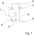
- a combustion plant is generally denoted by 1, which has a combustion air supply 2 and an exhaust gas guide 3.
- This combustion air supply 2 comprises a primary air feed 4 and a secondary air feed 5 with respective throttle devices.
- a bypass line 8 is provided with a throttle device 7.
- the combustion air or a part of the combustion air, bypassing the combustion chamber of the furnace 1 is to be guided directly into the exhaust system and thus into a connected to the exhaust duct 3 chimney.
- the furnace 1 is still equipped with a firebox door or a firebox door handle 9 and has an internal exhaust deflection. 6
- throttling device 7 is in Fig. 2 illustrated in more detail. It is a pressure-controlled throttle device, which forms the train control device together with the bypass line.
- bypass line 8 is located behind the combustion chamber of the furnace 1 and therefore not visible from a living room.
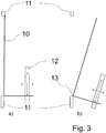
- the throttling device 10 of the draft control device can have an adjustable weight element 12 about an axis of rotation 13.
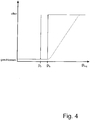
- the throttle valve 10 seals in the bypass line via the sealing surface 11. This can be done in dependence on a predeterminable train pressure in the chimney by the pressure shown in the chimney Fig. 2 the throttle valve remains closed and at a predefinable Pressure PA opens, be it stepwise and thus leaps to a fully open state or that it opens continuously, as shown by the dot representations in Fig. 4 is indicated. Conversely, the throttle valve is closed when falling below the pressure PA, as has already been described in more detail.
Landscapes
- Engineering & Computer Science (AREA)
- Chemical & Material Sciences (AREA)
- Combustion & Propulsion (AREA)
- Mechanical Engineering (AREA)
- General Engineering & Computer Science (AREA)
- Solid-Fuel Combustion (AREA)
- Regulation And Control Of Combustion (AREA)
Claims (15)
- Installation de chauffage (1), qui peut être alimenté en combustibles tels que du bois, de la paille ou d'autres combustibles renouvelables, ou en carbone, l'installation de chauffage comprenant une chambre de combustion pouvant être fermée et un raccord d'air de combustion muni d'une alimentation en air de combustion (2), la chambre de combustion comportant une alimentation en air primaire (4) et une alimentation en air secondaire (5) de l'alimentation en air de combustion (2) et un système d'évacuation des gaz (3) pouvant être raccordé à une cheminée, l'alimentation en air de combustion (2) comportant un conduit de dérivation (8) qui forme un dispositif de régulation de tirage de cheminée, qui relie l'alimentation en air de combustion (2) au système d'évacuation des gaz sans passer par la chambre de combustion et qui comporte au moins un dispositif d'étranglement (7) destiné à libérer, étrangler ou fermer le trajet d'écoulement à travers le conduit de dérivation (8) en fonction d'une pression de tirage de cheminée et l'alimentation en air de combustion (2) et/ou le système d'évacuation des gaz (3) comportant un dispositif d'étranglement d'écoulement, caractérisée en ce que l'alimentation en air de combustion (2) comporte une alimentation en air primaire (4) et une alimentation en air secondaire (5) munie de dispositifs d'étranglement respectifs.
- Installation de chauffage selon la revendication 1, caractérisée en ce que le conduit de dérivation (8) comporte une pluralité de conduits, un dispositif d'étranglement (7) qui réagit à la pression de tirage de cheminée étant destinés aux conduits.
- Installation de chauffage selon la revendication 1 ou 2, caractérisée en ce que le conduit de dérivation (8) comporte une pluralité de conduits munis chacun d'au moins un dispositif d'étranglement (7) réagissant à la pression de tirage de cheminée.
- Installation de chauffage l'une des revendications 1 à 3, caractérisée en ce que le dispositif d'étranglement (7) est réglable à une pression de tirage de cheminée prédéterminable et présente, lorsque cette pression de tirage de cheminée, une caractéristique en forme de marche.
- Installation de chauffage selon l'une des revendications 1 à 4, caractérisée en ce que le dispositif d'étranglement (7) est réglable à une pression de tirage de cheminée déterminée et présente, au-dessus de cette pression de tirage de cheminée, une caractéristique continue.
- Installation de chauffage selon l'une des revendications 1 à 5, caractérisée en ce que le dispositif d'étranglement (7) est réglé à une pression de tirage de cheminée entre 5 Pa et 50 Pa.
- Installation de chauffage selon l'une des revendications 1 à 6, caractérisée en ce que le dispositif d'étranglement (7) comporte des éléments d'amortissement de mouvement.
- Installation de chauffage selon la revendication 7, caractérisée en ce que le dispositif d'étranglement (7) comporte des éléments d'amortissement de mouvement à inertie.
- Installation de chauffage selon la revendication 8, caractérisée en ce que le dispositif d'étranglement (7) comporte des éléments d'amortissement de mouvement à friction.
- Installation de chauffage selon l'une des revendications 1 à 9, caractérisée en ce que l'alimentation en air de combustion (2) et/ou le système d'évacuation des gaz (3) comportent des moyens d'étranglement d'écoulement.
- Installation de chauffage selon l'une des revendications 1 à 10, caractérisée en ce que le système d'évacuation des gaz (3) comporte, en amont de sa sortie dans la cheminée, un dispositif d'étranglement.
- Installation de chauffage selon l'une des revendications 1 à 11, caractérisée en ce qu'au moins un dispositif d'étranglement à commande thermostatique est prévu dans l'alimentation en air de combustion (2), dans le système d'évacuation des gaz (3) et/ou le conduit de dérivation (8).
- Installation de chauffage selon l'une des revendications 1 à 12, caractérisée en ce qu'au moins un dispositif d'étranglement à commande manuel est prévu dans le système d'évacuation des gaz (3) et/ou dans l'alimentation en air de combustion (2) et/ou le conduit de dérivation (8).
- Installation de chauffage selon l'une des revendications 1 à 13, caractérisée en ce que le dispositif d'étranglement (7) est pourvu d'éléments de rappel réglables (12).
- Installation de chauffage selon la revendication 14, caractérisée en ce qu'un dispositif d'étranglement d'écoulement comprend un élément de rappel monté de façon mobile.
Priority Applications (1)
| Application Number | Priority Date | Filing Date | Title |
|---|---|---|---|
| PL08020870T PL2071243T3 (pl) | 2007-12-15 | 2008-12-02 | Instalacja paleniskowa, zwłaszcza piec kominkowy lub piec kaflowy |
Applications Claiming Priority (1)
| Application Number | Priority Date | Filing Date | Title |
|---|---|---|---|
| DE102007060656A DE102007060656B3 (de) | 2007-12-15 | 2007-12-15 | Feuerungsanlage, insbesondere Kamin- oder Kachelofen |
Publications (2)
| Publication Number | Publication Date |
|---|---|
| EP2071243A1 EP2071243A1 (fr) | 2009-06-17 |
| EP2071243B1 true EP2071243B1 (fr) | 2018-03-07 |
Family
ID=40348823
Family Applications (1)
| Application Number | Title | Priority Date | Filing Date |
|---|---|---|---|
| EP08020870.5A Not-in-force EP2071243B1 (fr) | 2007-12-15 | 2008-12-02 | Installation de combustion, notamment cheminées ou poêles en faïence |
Country Status (3)
| Country | Link |
|---|---|
| EP (1) | EP2071243B1 (fr) |
| DE (1) | DE102007060656B3 (fr) |
| PL (1) | PL2071243T3 (fr) |
Families Citing this family (3)
| Publication number | Priority date | Publication date | Assignee | Title |
|---|---|---|---|---|
| CN102444887A (zh) * | 2011-09-09 | 2012-05-09 | 王乾生 | 高强无热排可分离回用现温污排兼得高值渣的方法和炉 |
| WO2016182524A1 (fr) * | 2015-05-14 | 2016-11-17 | Вадим Григорьевич СТАНЧЕВ | Chauffe-eau à chaudière à combustible solide permettant d'assurer une combustion prolongée |
| DE202017001336U1 (de) * | 2017-03-14 | 2017-05-10 | Spartherm Feuerungstechnik Gmbh | Feuerungsanlage |
Family Cites Families (11)
| Publication number | Priority date | Publication date | Assignee | Title |
|---|---|---|---|---|
| CH182666A (de) * | 1935-02-08 | 1936-02-29 | Nievergelt Walter | Selbsttätiger nachstellbarer Kaminzugregler. |
| FR2558934B2 (fr) * | 1983-03-18 | 1987-02-27 | Telec 2000 | Installation de chauffage domestique a foyer ferme utilisant un combustible solide du type bois ou ses derives |
| FR2542849B1 (fr) * | 1983-03-18 | 1985-12-13 | Telec 2000 | Installation de chauffage domestique a foyer ferme utilisant un combustible solide du type bois ou ses derives |
| DE3743205A1 (de) * | 1987-12-19 | 1989-06-29 | Schrag Heizungs Lueftungs Klim | Brenneinrichtung |
| AU612060B2 (en) * | 1988-09-19 | 1991-06-27 | Richard James Gilham | Heater |
| FR2675886A1 (fr) * | 1991-04-26 | 1992-10-30 | Damon Raymond | Dispositif de desenfumage de la vitre dans les cheminees a foyer ferme. |
| FR2675887A1 (fr) * | 1991-04-26 | 1992-10-30 | Damon Raymond | Installation de chauffage de l'eau sanitaire a partir d'une cheminee a foyer ferme. |
| FR2701541B1 (fr) * | 1993-02-15 | 1995-04-07 | Gerard Gauthier | Gauthier Gérard. |
| WO2000050817A1 (fr) * | 1999-02-26 | 2000-08-31 | Fireplace Kft. | Piece rapportee pour poele |
| FR2794520B1 (fr) * | 1999-05-20 | 2001-09-14 | Denis Gravier | Dispositif de regulation de la temperature et de maitrise de la combustion d'un appareil de chauffage a foyer ferme |
| DE202004020320U1 (de) * | 2004-01-22 | 2005-04-21 | Bbt Thermotechnik Gmbh | Festbrennstoffkessel |
-
2007
- 2007-12-15 DE DE102007060656A patent/DE102007060656B3/de not_active Expired - Fee Related
-
2008
- 2008-12-02 EP EP08020870.5A patent/EP2071243B1/fr not_active Not-in-force
- 2008-12-02 PL PL08020870T patent/PL2071243T3/pl unknown
Non-Patent Citations (1)
| Title |
|---|
| None * |
Also Published As
| Publication number | Publication date |
|---|---|
| DE102007060656B3 (de) | 2009-03-19 |
| PL2071243T3 (pl) | 2018-10-31 |
| EP2071243A1 (fr) | 2009-06-17 |
Similar Documents
| Publication | Publication Date | Title |
|---|---|---|
| DE102009012905B3 (de) | Verfahren zur Regelung der Leistung eines Festbrennstoffofens und Ofen mit einer entsprechenden Leistungsregelung | |
| EP2221534B1 (fr) | Foyer de cheminée doté d'un régulateur d'arrivée d'air | |
| EP2208938B1 (fr) | Dispositif de combustion de combustibles solides | |
| EP2071243B1 (fr) | Installation de combustion, notamment cheminées ou poêles en faïence | |
| EP4031814A1 (fr) | Dispositif de chauffage | |
| AT389753B (de) | Belueftungsanordnung an einer feuerstaette | |
| AT505769B1 (de) | Ofen | |
| EP0409790A1 (fr) | Installation de combustion | |
| EP2878895B1 (fr) | Four de production de chaleur | |
| EP3376106B1 (fr) | Installation de combustion | |
| CH663083A5 (de) | Heizkessel. | |
| DE2054608C3 (de) | Brenneranordnung in Wärmöfen, insbesondere Tiefofen | |
| DE10012485A1 (de) | Einrichtung zur Steuerung der Zufuhr von Verbrennungsluft zum Brennraum einer Einzelfeuerstätte beispielsweise eines Ofens, Kaminofens, Herdes oder dergleichen | |
| DE102015105547B4 (de) | Brenneinsatz für Sturzbrandöfen und Sturzbrandofen | |
| DE2836251C3 (de) | Anordnung zur Rauchgasführung und Rauchgasentnahme in einem Wärmekessel | |
| DE102023109080B3 (de) | Festbrennstofffeuerstätte für den häuslichen Bereich | |
| DE29905204U1 (de) | Gasregelarmatur | |
| AT527509B1 (de) | Wärmetauscher | |
| EP2287551B1 (fr) | Batterie chaude terminale pour installation de combustion | |
| DE2427886A1 (de) | Verfahren zur verhinderung von waermeverlusten an mit fluessigen und gasfoermigen brennstoffen betriebenen heizungsanlagen und vorrichtung zur durchfuehrung des verfahrens | |
| DE102018202404A1 (de) | Vorwärmsystem für Rauchgasleitungen | |
| DE703019C (de) | Feuerung, insbesondere fuer Heizungskessel | |
| DE4325239C2 (de) | Heizkessel zum Verbrennen von Holz | |
| AT119137B (de) | Kühlvorrichtung für Roste. | |
| AT230062B (de) | Vorrichtung an Heizöfen für feste Brennstoffe zur selbsttätigen Regelung der Verbrennungsluftzufuhr |
Legal Events
| Date | Code | Title | Description |
|---|---|---|---|
| PUAI | Public reference made under article 153(3) epc to a published international application that has entered the european phase |
Free format text: ORIGINAL CODE: 0009012 |
|
| AK | Designated contracting states |
Kind code of ref document: A1 Designated state(s): AT BE BG CH CY CZ DE DK EE ES FI FR GB GR HR HU IE IS IT LI LT LU LV MC MT NL NO PL PT RO SE SI SK TR |
|
| AX | Request for extension of the european patent |
Extension state: AL BA MK RS |
|
| 17P | Request for examination filed |
Effective date: 20091214 |
|
| 17Q | First examination report despatched |
Effective date: 20100120 |
|
| AKX | Designation fees paid |
Designated state(s): AT BE BG CH CY CZ DE DK EE ES FI FR GB GR HR HU IE IS IT LI LT LU LV MC MT NL NO PL PT RO SE SI SK TR |
|
| GRAP | Despatch of communication of intention to grant a patent |
Free format text: ORIGINAL CODE: EPIDOSNIGR1 |
|
| RIC1 | Information provided on ipc code assigned before grant |
Ipc: F24B 5/02 20060101ALI20170503BHEP Ipc: F24B 1/02 20060101AFI20170503BHEP Ipc: F23L 11/02 20060101ALI20170503BHEP Ipc: F23L 13/02 20060101ALI20170503BHEP Ipc: F23N 3/04 20060101ALI20170503BHEP |
|
| STAA | Information on the status of an ep patent application or granted ep patent |
Free format text: STATUS: GRANT OF PATENT IS INTENDED |
|
| INTG | Intention to grant announced |
Effective date: 20170608 |
|
| GRAS | Grant fee paid |
Free format text: ORIGINAL CODE: EPIDOSNIGR3 |
|
| GRAA | (expected) grant |
Free format text: ORIGINAL CODE: 0009210 |
|
| STAA | Information on the status of an ep patent application or granted ep patent |
Free format text: STATUS: THE PATENT HAS BEEN GRANTED |
|
| AK | Designated contracting states |
Kind code of ref document: B1 Designated state(s): AT BE BG CH CY CZ DE DK EE ES FI FR GB GR HR HU IE IS IT LI LT LU LV MC MT NL NO PL PT RO SE SI SK TR |
|
| REG | Reference to a national code |
Ref country code: GB Ref legal event code: FG4D Free format text: NOT ENGLISH |
|
| REG | Reference to a national code |
Ref country code: CH Ref legal event code: EP Ref country code: AT Ref legal event code: REF Ref document number: 976982 Country of ref document: AT Kind code of ref document: T Effective date: 20180315 |
|
| REG | Reference to a national code |
Ref country code: IE Ref legal event code: FG4D Free format text: LANGUAGE OF EP DOCUMENT: GERMAN |
|
| REG | Reference to a national code |
Ref country code: DE Ref legal event code: R096 Ref document number: 502008015932 Country of ref document: DE |
|
| REG | Reference to a national code |
Ref country code: SE Ref legal event code: TRGR |
|
| REG | Reference to a national code |
Ref country code: NL Ref legal event code: FP |
|
| REG | Reference to a national code |
Ref country code: LT Ref legal event code: MG4D |
|
| PG25 | Lapsed in a contracting state [announced via postgrant information from national office to epo] |
Ref country code: NO Free format text: LAPSE BECAUSE OF FAILURE TO SUBMIT A TRANSLATION OF THE DESCRIPTION OR TO PAY THE FEE WITHIN THE PRESCRIBED TIME-LIMIT Effective date: 20180607 Ref country code: FI Free format text: LAPSE BECAUSE OF FAILURE TO SUBMIT A TRANSLATION OF THE DESCRIPTION OR TO PAY THE FEE WITHIN THE PRESCRIBED TIME-LIMIT Effective date: 20180307 Ref country code: CY Free format text: LAPSE BECAUSE OF FAILURE TO SUBMIT A TRANSLATION OF THE DESCRIPTION OR TO PAY THE FEE WITHIN THE PRESCRIBED TIME-LIMIT Effective date: 20180307 Ref country code: ES Free format text: LAPSE BECAUSE OF FAILURE TO SUBMIT A TRANSLATION OF THE DESCRIPTION OR TO PAY THE FEE WITHIN THE PRESCRIBED TIME-LIMIT Effective date: 20180307 Ref country code: HR Free format text: LAPSE BECAUSE OF FAILURE TO SUBMIT A TRANSLATION OF THE DESCRIPTION OR TO PAY THE FEE WITHIN THE PRESCRIBED TIME-LIMIT Effective date: 20180307 Ref country code: LT Free format text: LAPSE BECAUSE OF FAILURE TO SUBMIT A TRANSLATION OF THE DESCRIPTION OR TO PAY THE FEE WITHIN THE PRESCRIBED TIME-LIMIT Effective date: 20180307 |
|
| PG25 | Lapsed in a contracting state [announced via postgrant information from national office to epo] |
Ref country code: BG Free format text: LAPSE BECAUSE OF FAILURE TO SUBMIT A TRANSLATION OF THE DESCRIPTION OR TO PAY THE FEE WITHIN THE PRESCRIBED TIME-LIMIT Effective date: 20180607 Ref country code: LV Free format text: LAPSE BECAUSE OF FAILURE TO SUBMIT A TRANSLATION OF THE DESCRIPTION OR TO PAY THE FEE WITHIN THE PRESCRIBED TIME-LIMIT Effective date: 20180307 Ref country code: GR Free format text: LAPSE BECAUSE OF FAILURE TO SUBMIT A TRANSLATION OF THE DESCRIPTION OR TO PAY THE FEE WITHIN THE PRESCRIBED TIME-LIMIT Effective date: 20180608 |
|
| REG | Reference to a national code |
Ref country code: CH Ref legal event code: NV Representative=s name: SCHNEIDER FELDMANN AG PATENT- UND MARKENANWAEL, CH |
|
| PG25 | Lapsed in a contracting state [announced via postgrant information from national office to epo] |
Ref country code: MT Free format text: LAPSE BECAUSE OF FAILURE TO SUBMIT A TRANSLATION OF THE DESCRIPTION OR TO PAY THE FEE WITHIN THE PRESCRIBED TIME-LIMIT Effective date: 20180307 |
|
| PG25 | Lapsed in a contracting state [announced via postgrant information from national office to epo] |
Ref country code: EE Free format text: LAPSE BECAUSE OF FAILURE TO SUBMIT A TRANSLATION OF THE DESCRIPTION OR TO PAY THE FEE WITHIN THE PRESCRIBED TIME-LIMIT Effective date: 20180307 Ref country code: RO Free format text: LAPSE BECAUSE OF FAILURE TO SUBMIT A TRANSLATION OF THE DESCRIPTION OR TO PAY THE FEE WITHIN THE PRESCRIBED TIME-LIMIT Effective date: 20180307 Ref country code: IT Free format text: LAPSE BECAUSE OF FAILURE TO SUBMIT A TRANSLATION OF THE DESCRIPTION OR TO PAY THE FEE WITHIN THE PRESCRIBED TIME-LIMIT Effective date: 20180307 |
|
| REG | Reference to a national code |
Ref country code: DE Ref legal event code: R097 Ref document number: 502008015932 Country of ref document: DE |
|
| PG25 | Lapsed in a contracting state [announced via postgrant information from national office to epo] |
Ref country code: PT Free format text: LAPSE BECAUSE OF FAILURE TO SUBMIT A TRANSLATION OF THE DESCRIPTION OR TO PAY THE FEE WITHIN THE PRESCRIBED TIME-LIMIT Effective date: 20180709 |
|
| PLBE | No opposition filed within time limit |
Free format text: ORIGINAL CODE: 0009261 |
|
| STAA | Information on the status of an ep patent application or granted ep patent |
Free format text: STATUS: NO OPPOSITION FILED WITHIN TIME LIMIT |
|
| PG25 | Lapsed in a contracting state [announced via postgrant information from national office to epo] |
Ref country code: DK Free format text: LAPSE BECAUSE OF FAILURE TO SUBMIT A TRANSLATION OF THE DESCRIPTION OR TO PAY THE FEE WITHIN THE PRESCRIBED TIME-LIMIT Effective date: 20180307 |
|
| PGFP | Annual fee paid to national office [announced via postgrant information from national office to epo] |
Ref country code: AT Payment date: 20181212 Year of fee payment: 11 Ref country code: NL Payment date: 20181220 Year of fee payment: 11 Ref country code: CZ Payment date: 20181102 Year of fee payment: 11 Ref country code: SE Payment date: 20181218 Year of fee payment: 11 Ref country code: PL Payment date: 20181030 Year of fee payment: 11 |
|
| 26N | No opposition filed |
Effective date: 20181210 |
|
| PG25 | Lapsed in a contracting state [announced via postgrant information from national office to epo] |
Ref country code: SI Free format text: LAPSE BECAUSE OF FAILURE TO SUBMIT A TRANSLATION OF THE DESCRIPTION OR TO PAY THE FEE WITHIN THE PRESCRIBED TIME-LIMIT Effective date: 20180307 |
|
| PGFP | Annual fee paid to national office [announced via postgrant information from national office to epo] |
Ref country code: FR Payment date: 20181226 Year of fee payment: 11 Ref country code: GB Payment date: 20181112 Year of fee payment: 11 |
|
| REG | Reference to a national code |
Ref country code: SK Ref legal event code: T3 Ref document number: E 28845 Country of ref document: SK |
|
| PGFP | Annual fee paid to national office [announced via postgrant information from national office to epo] |
Ref country code: CH Payment date: 20190329 Year of fee payment: 11 |
|
| PGFP | Annual fee paid to national office [announced via postgrant information from national office to epo] |
Ref country code: SK Payment date: 20181107 Year of fee payment: 11 |
|
| PG25 | Lapsed in a contracting state [announced via postgrant information from national office to epo] |
Ref country code: LU Free format text: LAPSE BECAUSE OF NON-PAYMENT OF DUE FEES Effective date: 20181202 Ref country code: MC Free format text: LAPSE BECAUSE OF FAILURE TO SUBMIT A TRANSLATION OF THE DESCRIPTION OR TO PAY THE FEE WITHIN THE PRESCRIBED TIME-LIMIT Effective date: 20180307 |
|
| REG | Reference to a national code |
Ref country code: IE Ref legal event code: MM4A |
|
| REG | Reference to a national code |
Ref country code: BE Ref legal event code: MM Effective date: 20181231 |
|
| PG25 | Lapsed in a contracting state [announced via postgrant information from national office to epo] |
Ref country code: IE Free format text: LAPSE BECAUSE OF NON-PAYMENT OF DUE FEES Effective date: 20181202 |
|
| PG25 | Lapsed in a contracting state [announced via postgrant information from national office to epo] |
Ref country code: BE Free format text: LAPSE BECAUSE OF NON-PAYMENT OF DUE FEES Effective date: 20181231 |
|
| PG25 | Lapsed in a contracting state [announced via postgrant information from national office to epo] |
Ref country code: TR Free format text: LAPSE BECAUSE OF FAILURE TO SUBMIT A TRANSLATION OF THE DESCRIPTION OR TO PAY THE FEE WITHIN THE PRESCRIBED TIME-LIMIT Effective date: 20180307 |
|
| PG25 | Lapsed in a contracting state [announced via postgrant information from national office to epo] |
Ref country code: HU Free format text: LAPSE BECAUSE OF FAILURE TO SUBMIT A TRANSLATION OF THE DESCRIPTION OR TO PAY THE FEE WITHIN THE PRESCRIBED TIME-LIMIT; INVALID AB INITIO Effective date: 20081202 |
|
| REG | Reference to a national code |
Ref country code: SE Ref legal event code: EUG |
|
| PG25 | Lapsed in a contracting state [announced via postgrant information from national office to epo] |
Ref country code: CZ Free format text: LAPSE BECAUSE OF NON-PAYMENT OF DUE FEES Effective date: 20191202 Ref country code: IS Free format text: LAPSE BECAUSE OF FAILURE TO SUBMIT A TRANSLATION OF THE DESCRIPTION OR TO PAY THE FEE WITHIN THE PRESCRIBED TIME-LIMIT Effective date: 20180707 |
|
| REG | Reference to a national code |
Ref country code: CH Ref legal event code: PL |
|
| REG | Reference to a national code |
Ref country code: NL Ref legal event code: MM Effective date: 20200101 |
|
| REG | Reference to a national code |
Ref country code: AT Ref legal event code: MM01 Ref document number: 976982 Country of ref document: AT Kind code of ref document: T Effective date: 20191202 |
|
| GBPC | Gb: european patent ceased through non-payment of renewal fee |
Effective date: 20191202 |
|
| REG | Reference to a national code |
Ref country code: SK Ref legal event code: MM4A Ref document number: E 28845 Country of ref document: SK Effective date: 20191202 |
|
| PG25 | Lapsed in a contracting state [announced via postgrant information from national office to epo] |
Ref country code: NL Free format text: LAPSE BECAUSE OF NON-PAYMENT OF DUE FEES Effective date: 20200101 |
|
| PG25 | Lapsed in a contracting state [announced via postgrant information from national office to epo] |
Ref country code: GB Free format text: LAPSE BECAUSE OF NON-PAYMENT OF DUE FEES Effective date: 20191202 Ref country code: SE Free format text: LAPSE BECAUSE OF NON-PAYMENT OF DUE FEES Effective date: 20191203 Ref country code: FR Free format text: LAPSE BECAUSE OF NON-PAYMENT OF DUE FEES Effective date: 20191231 Ref country code: SK Free format text: LAPSE BECAUSE OF NON-PAYMENT OF DUE FEES Effective date: 20191202 |
|
| PG25 | Lapsed in a contracting state [announced via postgrant information from national office to epo] |
Ref country code: LI Free format text: LAPSE BECAUSE OF NON-PAYMENT OF DUE FEES Effective date: 20191231 Ref country code: CH Free format text: LAPSE BECAUSE OF NON-PAYMENT OF DUE FEES Effective date: 20191231 Ref country code: AT Free format text: LAPSE BECAUSE OF NON-PAYMENT OF DUE FEES Effective date: 20191202 |
|
| PG25 | Lapsed in a contracting state [announced via postgrant information from national office to epo] |
Ref country code: PL Free format text: LAPSE BECAUSE OF NON-PAYMENT OF DUE FEES Effective date: 20191202 |
|
| PGFP | Annual fee paid to national office [announced via postgrant information from national office to epo] |
Ref country code: DE Payment date: 20221020 Year of fee payment: 15 |
|
| REG | Reference to a national code |
Ref country code: DE Ref legal event code: R119 Ref document number: 502008015932 Country of ref document: DE |
|
| PG25 | Lapsed in a contracting state [announced via postgrant information from national office to epo] |
Ref country code: DE Free format text: LAPSE BECAUSE OF NON-PAYMENT OF DUE FEES Effective date: 20240702 |
|
| PG25 | Lapsed in a contracting state [announced via postgrant information from national office to epo] |
Ref country code: DE Free format text: LAPSE BECAUSE OF NON-PAYMENT OF DUE FEES Effective date: 20240702 |