EP2071245A2 - Installation de chauffage - Google Patents
Installation de chauffage Download PDFInfo
- Publication number
- EP2071245A2 EP2071245A2 EP08021435A EP08021435A EP2071245A2 EP 2071245 A2 EP2071245 A2 EP 2071245A2 EP 08021435 A EP08021435 A EP 08021435A EP 08021435 A EP08021435 A EP 08021435A EP 2071245 A2 EP2071245 A2 EP 2071245A2
- Authority
- EP
- European Patent Office
- Prior art keywords
- heat
- control unit
- central control
- heating system
- heat generator
- Prior art date
- Legal status (The legal status is an assumption and is not a legal conclusion. Google has not performed a legal analysis and makes no representation as to the accuracy of the status listed.)
- Withdrawn
Links
- 238000010438 heat treatment Methods 0.000 title claims description 28
- 238000000034 method Methods 0.000 claims abstract description 9
- 238000010586 diagram Methods 0.000 claims description 7
- 230000003993 interaction Effects 0.000 claims description 6
- 238000009434 installation Methods 0.000 claims 1
- 238000005338 heat storage Methods 0.000 description 7
- 238000009420 retrofitting Methods 0.000 description 3
- XLYOFNOQVPJJNP-UHFFFAOYSA-N water Substances O XLYOFNOQVPJJNP-UHFFFAOYSA-N 0.000 description 3
- 230000001419 dependent effect Effects 0.000 description 2
- 238000011161 development Methods 0.000 description 2
- 230000018109 developmental process Effects 0.000 description 2
- 238000004891 communication Methods 0.000 description 1
Images
Classifications
-
- F—MECHANICAL ENGINEERING; LIGHTING; HEATING; WEAPONS; BLASTING
- F24—HEATING; RANGES; VENTILATING
- F24D—DOMESTIC- OR SPACE-HEATING SYSTEMS, e.g. CENTRAL HEATING SYSTEMS; DOMESTIC HOT-WATER SUPPLY SYSTEMS; ELEMENTS OR COMPONENTS THEREFOR
- F24D12/00—Other central heating systems
- F24D12/02—Other central heating systems having more than one heat source
-
- F—MECHANICAL ENGINEERING; LIGHTING; HEATING; WEAPONS; BLASTING
- F24—HEATING; RANGES; VENTILATING
- F24D—DOMESTIC- OR SPACE-HEATING SYSTEMS, e.g. CENTRAL HEATING SYSTEMS; DOMESTIC HOT-WATER SUPPLY SYSTEMS; ELEMENTS OR COMPONENTS THEREFOR
- F24D19/00—Details
- F24D19/10—Arrangement or mounting of control or safety devices
- F24D19/1006—Arrangement or mounting of control or safety devices for water heating systems
- F24D19/1009—Arrangement or mounting of control or safety devices for water heating systems for central heating
-
- F—MECHANICAL ENGINEERING; LIGHTING; HEATING; WEAPONS; BLASTING
- F24—HEATING; RANGES; VENTILATING
- F24D—DOMESTIC- OR SPACE-HEATING SYSTEMS, e.g. CENTRAL HEATING SYSTEMS; DOMESTIC HOT-WATER SUPPLY SYSTEMS; ELEMENTS OR COMPONENTS THEREFOR
- F24D2200/00—Heat sources or energy sources
- F24D2200/04—Gas or oil fired boiler
-
- F—MECHANICAL ENGINEERING; LIGHTING; HEATING; WEAPONS; BLASTING
- F24—HEATING; RANGES; VENTILATING
- F24D—DOMESTIC- OR SPACE-HEATING SYSTEMS, e.g. CENTRAL HEATING SYSTEMS; DOMESTIC HOT-WATER SUPPLY SYSTEMS; ELEMENTS OR COMPONENTS THEREFOR
- F24D2200/00—Heat sources or energy sources
- F24D2200/12—Heat pump
-
- F—MECHANICAL ENGINEERING; LIGHTING; HEATING; WEAPONS; BLASTING
- F24—HEATING; RANGES; VENTILATING
- F24D—DOMESTIC- OR SPACE-HEATING SYSTEMS, e.g. CENTRAL HEATING SYSTEMS; DOMESTIC HOT-WATER SUPPLY SYSTEMS; ELEMENTS OR COMPONENTS THEREFOR
- F24D2200/00—Heat sources or energy sources
- F24D2200/14—Solar energy
-
- Y—GENERAL TAGGING OF NEW TECHNOLOGICAL DEVELOPMENTS; GENERAL TAGGING OF CROSS-SECTIONAL TECHNOLOGIES SPANNING OVER SEVERAL SECTIONS OF THE IPC; TECHNICAL SUBJECTS COVERED BY FORMER USPC CROSS-REFERENCE ART COLLECTIONS [XRACs] AND DIGESTS
- Y02—TECHNOLOGIES OR APPLICATIONS FOR MITIGATION OR ADAPTATION AGAINST CLIMATE CHANGE
- Y02B—CLIMATE CHANGE MITIGATION TECHNOLOGIES RELATED TO BUILDINGS, e.g. HOUSING, HOUSE APPLIANCES OR RELATED END-USER APPLICATIONS
- Y02B10/00—Integration of renewable energy sources in buildings
- Y02B10/20—Solar thermal
-
- Y—GENERAL TAGGING OF NEW TECHNOLOGICAL DEVELOPMENTS; GENERAL TAGGING OF CROSS-SECTIONAL TECHNOLOGIES SPANNING OVER SEVERAL SECTIONS OF THE IPC; TECHNICAL SUBJECTS COVERED BY FORMER USPC CROSS-REFERENCE ART COLLECTIONS [XRACs] AND DIGESTS
- Y02—TECHNOLOGIES OR APPLICATIONS FOR MITIGATION OR ADAPTATION AGAINST CLIMATE CHANGE
- Y02B—CLIMATE CHANGE MITIGATION TECHNOLOGIES RELATED TO BUILDINGS, e.g. HOUSING, HOUSE APPLIANCES OR RELATED END-USER APPLICATIONS
- Y02B10/00—Integration of renewable energy sources in buildings
- Y02B10/70—Hybrid systems, e.g. uninterruptible or back-up power supplies integrating renewable energies
-
- Y—GENERAL TAGGING OF NEW TECHNOLOGICAL DEVELOPMENTS; GENERAL TAGGING OF CROSS-SECTIONAL TECHNOLOGIES SPANNING OVER SEVERAL SECTIONS OF THE IPC; TECHNICAL SUBJECTS COVERED BY FORMER USPC CROSS-REFERENCE ART COLLECTIONS [XRACs] AND DIGESTS
- Y02—TECHNOLOGIES OR APPLICATIONS FOR MITIGATION OR ADAPTATION AGAINST CLIMATE CHANGE
- Y02B—CLIMATE CHANGE MITIGATION TECHNOLOGIES RELATED TO BUILDINGS, e.g. HOUSING, HOUSE APPLIANCES OR RELATED END-USER APPLICATIONS
- Y02B30/00—Energy efficient heating, ventilation or air conditioning [HVAC]
Definitions
- the invention relates to a heating system according to the preamble of patent claim 1.
- a heating system of the type mentioned is known per se. It consists of at least two heat generators (for example: boiler, solar system, heat pump, etc.) and typically a heat storage (usually a hot water tank), the heat generator each having at least one switching unit for controlling heat generator internal processes (ie an electrical or electronic circuit responsible for linking together the internal components of the heat generator), each switching unit having a higher-level central control unit (known, for example, the Applotronic Vitotronic® 333 cascade control housed in its own control housing) for coordinating the hydraulic interaction, in particular of the heat generators , but also the heat accumulator is connected, wherein the central control unit is designed for initial storage of a hydraulic circuit diagram of the heat generator and optionally the heat accumulator, d. H.
- the central control unit is designed for initial storage of a hydraulic circuit diagram of the heat generator and optionally the heat accumulator, d. H.
- commissioning the heating system of the central control unit is informed by the operator how the heat generator and heat storage are hydraulically linked together, so
- the invention has for its object to produce a heating system of the type mentioned cost and offer.
- At least one of the heat generators has the central control unit as an integral part.
- the central control unit is integrated in at least one of the heat generator, so that a separate housing is dispensable.
- this requirement has a further significant advantage, which can be seen by considering the case study of retrofitting existing existing plants:
- a central control unit is then integrated into a heat pump to be retrofitted, then after the operator, who is guided via a suitable input menu, has stored the concrete hydraulic circuit diagram in it, he can take complete control of the entire heating system, without It would be necessary to provide an overall higher-level, separately installed central control unit such as the Vitotronic® 333.
- the heat generators are ultimately simply connected to one another via a standard interface and operated by a kind of standardized network cable. If there are several central control units (for example, because both a heat pump and a solar system with central control unit has been retrofitted), one is defined as the decisive and the other switched off or simply ignored.
- the purchase of a arranged in a separate housing central control unit is eliminated, which obviously significantly reduces the cost of retrofitting an existing heating system.
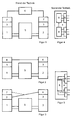
- FIG. 1 First, a known according to the prior art heating system is shown. This consists of two heat generators 1, 2 (for example, a gas boiler and a heat pump), each having a switching unit 3 for controlling heat generator internal processes.
- each heat generator 1, 2 a single control unit 7, which serves to control the individual heat generator 1, 2.
- This single control unit 7 is in close contact with the switching unit 3 (for example, the automatic burner control of a boiler), which, as mentioned, not for control, but only for electrical connection of the individual components of the heat generator 1, 2 is used.
- Each individual control unit 7 is equipped with software that is tailored to the characteristics of the respective heat generator 1, 2.
- the software of the individual control unit 7 of the one heat generator 1 does not know the characteristics of the other heat generator 2, that is to say it is in each case heat generator-specific software, which is stored in each case in a main processor.
- each switching unit 3 is connected (via the individual control unit 7) to a higher-level central control unit 4 (for coordinating the hydraulic interaction) of the heat generators 1, 2.
- the central control unit 4 for initial storage of a hydraulic circuit diagram of the heat generator 1, 2 is formed.
- these two heating systems also have two heat generators 1, 2, each having a switching unit 3 for controlling heat-generator-internal processes, each switching unit 3 having a higher-level central control unit 4 for coordinating the hydraulic interaction of the heat generators 1, 2, wherein the central control unit 4 for initial storage of a hydraulic circuit diagram of the heat generator 1, 2 is formed.
- Both heat generators 1, 2 have such a central control unit 4.
- it is thus typically a heating system, which is constructed from heat generators 1, 2 according to the invention with central control unit 4.
- one of the two central control units 4 takes over control of the entire system in the illustrated case, while the other central control unit 4 ultimately only serves to forward the information from the switching unit 3 on.
- FIG. 3 shows the typical situation when retrofitting an existing old heating system.
- the heat generator 1 for example, a boiler
- the heat generator 2 for example, a heat pump or a solar system, but also another boiler is possible [cascade solution]
- this invention comprises not only a single control unit 7, but a higher-level central control unit 4, this retrofitted device can directly take over the control of the entire system.
- the central control unit 4 only with the heat generator 1 or the switching unit 3 or (shown in phantom) to be connected to the single control unit 7.
- FIGS. 1 to 3 there is the one in the FIGS. 1 to 3 illustrated, known per se heat storage 5 to explain.
- These are, for example, a so-called bivalent hot water tank, to which heat can be supplied via the two heat generators 1, 2. Since often the interconnection of the heating system is not so simple, as shown, is formed, it is particularly preferably provided that the central control unit 4 for coordinating the hydraulic interaction and preferably for initial storage of a hydraulic circuit diagram of both the heat generator 1, 2 and the heat accumulator 5 is formed ,
- FIG. 4 a central control unit 4 according to the known, prior art explained.
- This has a plurality of (here for simplicity only shown two) interfaces 6 for connection of optional switching 3 and / or individual control units 7.
- Each interface 6 is associated with a processor 8, are stored on the heat generator specific characteristics.
- the processors 8 themselves are also interconnected to allow control of the overall system.
- inventive embodiment of the central control unit 4 is after FIG. 5 and in contrast to the usual solution after FIG. 4 provided that the central control unit 4 has a with all interfaces 4 at least in phases connected main processor 8. According to the invention thus becomes a slightly larger main processor 8 is provided, but overall is less expensive than several, smaller main processors 8 (see FIG. 4 ).
- the main processor 8 is a different characteristics of heat generators 1, 2 stored software is stored, which is particularly preferably provided that the various characteristics are stored in layers in the main processor 8 and retrievable.
- the software stored in the main processor 8 consists of at least two modules, wherein the first module is designed to take over general, heat generator-specific control functions and the second module for receiving and executing several, heat generator specific characteristics.
- a third module for receiving and execution of heat consumer specific characteristics may be provided.
- FIG. 4 requires the main processor 8 according to FIG. 5 namely not just the X-fold amount of storage space (where X is the number of main processor 8 in FIG.
Landscapes
- Engineering & Computer Science (AREA)
- Physics & Mathematics (AREA)
- Thermal Sciences (AREA)
- Chemical & Material Sciences (AREA)
- Combustion & Propulsion (AREA)
- Mechanical Engineering (AREA)
- General Engineering & Computer Science (AREA)
- Central Heating Systems (AREA)
- Air-Conditioning For Vehicles (AREA)
- Heat-Pump Type And Storage Water Heaters (AREA)
Applications Claiming Priority (1)
| Application Number | Priority Date | Filing Date | Title |
|---|---|---|---|
| DE102007061415A DE102007061415A1 (de) | 2007-12-16 | 2007-12-16 | Heizungsanlage |
Publications (2)
| Publication Number | Publication Date |
|---|---|
| EP2071245A2 true EP2071245A2 (fr) | 2009-06-17 |
| EP2071245A3 EP2071245A3 (fr) | 2012-08-15 |
Family
ID=40445624
Family Applications (1)
| Application Number | Title | Priority Date | Filing Date |
|---|---|---|---|
| EP08021435A Withdrawn EP2071245A3 (fr) | 2007-12-16 | 2008-12-10 | Installation de chauffage |
Country Status (2)
| Country | Link |
|---|---|
| EP (1) | EP2071245A3 (fr) |
| DE (1) | DE102007061415A1 (fr) |
Cited By (1)
| Publication number | Priority date | Publication date | Assignee | Title |
|---|---|---|---|---|
| RU2474770C2 (ru) * | 2011-03-30 | 2013-02-10 | Государственное научное учреждение Всероссийский научно-исследовательский технологический институт ремонта и эксплуатации машинно-тракторного парка Российской академии сельскохозяйственных наук (ГНУ ГОСНИТИ РОССЕЛЬХОЗАКАДЕМИИ) | Теплообменная система, использующая тепловые насосы (варианты) |
Families Citing this family (3)
| Publication number | Priority date | Publication date | Assignee | Title |
|---|---|---|---|---|
| DE102016205036B4 (de) * | 2016-03-24 | 2018-12-13 | Viessmann Werke Gmbh & Co Kg | Verfahren zum Steuern einer Energieversorgungsanlage |
| DE102016205033A1 (de) * | 2016-03-24 | 2017-09-28 | Viessmann Werke Gmbh & Co Kg | Vorrichtung und Verfahren zum Konfigurieren einer multivalenten Energieversorgungsanlage |
| DE102016205028A1 (de) * | 2016-03-24 | 2017-09-28 | Viessmann Werke Gmbh & Co Kg | Verfahren zum Steuern einer multivalenten Energieversorgungsanlage |
Family Cites Families (6)
| Publication number | Priority date | Publication date | Assignee | Title |
|---|---|---|---|---|
| US4627483A (en) * | 1984-01-09 | 1986-12-09 | Visual Information Institute, Inc. | Heat pump control system |
| EP0445310A1 (fr) * | 1990-02-09 | 1991-09-11 | Viessmann Werke GmbH & Co. | Procédé et dispositif de régulation de la température "aller" d'un système de chauffage à plusieures chaudières |
| DE19816165B4 (de) * | 1998-04-09 | 2006-02-23 | Viessmann Werke Gmbh & Co Kg | Verfahren und Vorrichtung für die Inbetriebnahme einer Heizungsanlage |
| DE29812549U1 (de) * | 1998-07-14 | 1998-10-08 | Viessmann Werke GmbH & Co., 35108 Allendorf | Anschlußvorrichtung, Heizungsregelung und Heizungsanlage |
| DE10105959A1 (de) * | 2001-02-09 | 2002-08-14 | Viessmann Werke Kg | Heizungs- und Kühleinrichtungen und Verfahren zur Datenkommunikation in solchen Einrichtungen |
| DE10326263A1 (de) * | 2003-06-11 | 2005-01-05 | Robert Bosch Gmbh | Schalt- und/oder Verteilungseinheit für Fluide und Verfahren zur Programmierung bzw. zum Betrieb einer hydraulischen oder pneumatischen Anlage |
-
2007
- 2007-12-16 DE DE102007061415A patent/DE102007061415A1/de not_active Ceased
-
2008
- 2008-12-10 EP EP08021435A patent/EP2071245A3/fr not_active Withdrawn
Non-Patent Citations (1)
| Title |
|---|
| "Modul (Software", 2 November 2007 (2007-11-02), XP055059637, Retrieved from the Internet <URL:http://de.wikipedia.org/w/index.php?title=Modul_(Software)&oldid=38524371> [retrieved on 20130415] * |
Cited By (1)
| Publication number | Priority date | Publication date | Assignee | Title |
|---|---|---|---|---|
| RU2474770C2 (ru) * | 2011-03-30 | 2013-02-10 | Государственное научное учреждение Всероссийский научно-исследовательский технологический институт ремонта и эксплуатации машинно-тракторного парка Российской академии сельскохозяйственных наук (ГНУ ГОСНИТИ РОССЕЛЬХОЗАКАДЕМИИ) | Теплообменная система, использующая тепловые насосы (варианты) |
Also Published As
| Publication number | Publication date |
|---|---|
| DE102007061415A1 (de) | 2009-07-23 |
| EP2071245A3 (fr) | 2012-08-15 |
Similar Documents
| Publication | Publication Date | Title |
|---|---|---|
| EP1950096B1 (fr) | Système modulaire | |
| DE20009207U1 (de) | Einrichtung zur Signalübertragung | |
| WO2001082668A1 (fr) | Systeme modulaire a dispositifs de commutation de securite | |
| AT521799A2 (de) | Verfahren zur Kaskadierung von elektronischen Schlossverriegelungen | |
| EP2071245A2 (fr) | Installation de chauffage | |
| DD297737A5 (de) | Verkabelungssystem fuer fahrzeuge | |
| DE102013108910A1 (de) | Elektromagnetventilsteuervorrichtung | |
| EP0740082A1 (fr) | Dispositif électrique modulaire pour un assemblage de bloc de vannes | |
| EP0853366A2 (fr) | Dispositif pour la transmission de signaux de commande à des vannes | |
| DE102012003023A1 (de) | Energieversorgungseinheit zur Energieversorgung eines Fahrzeugs | |
| EP2607200B1 (fr) | Agencement comprenant deux composants de véhicule, notamment une colonne de direction et un volant, et véhicule automobile doté d'un agencement | |
| DE102012107216B4 (de) | Elektrischer/elektronischer Aktor | |
| WO2008074609A2 (fr) | Appareil de terrain bifilaire pour la technique d'automatisation de procédés destinée à connecter au moins un élément de capteur | |
| EP1183577B1 (fr) | Procede de production d'un bloc de controle, et bloc de controle y relatif | |
| EP1089147B1 (fr) | Méthode et dispositif pour initialiser un nombre d'appareils de commande identiques | |
| AT509181A2 (de) | Multifunktionales ein- und ausgangsmodul für speicherprogrammierbare steuerungen | |
| EP1989599B1 (fr) | Appareil de commutation destiné à sécuriser des machines dangereuses | |
| EP3874473A1 (fr) | Procédé pour le montage en cascade de verrouillages électroniques | |
| DE102007028643A1 (de) | Reiheneinbaugeräte und Reiheneinbaugeräteensemble | |
| EP3731039B1 (fr) | Système d'installation électrique/électronique | |
| EP2093845B1 (fr) | Commande de sécurité modulaire | |
| WO2019092151A1 (fr) | Équipement électronique comprenant une ou plusieurs unités d'étage terminal pour le fonctionnement de deux ou de plusieurs unités moteur | |
| EP4329200A1 (fr) | Appareil de chauffage avec un boîtier | |
| DE2354053A1 (de) | Anordnung zur verknuepfung von schaltungselementen auf einer typisierten leiterkarte, wobei durch aufstecker zusaetzlicher interner steckverbinder eine verbindung entsprechend dem jeweiligen anwendungsfall erfolgt | |
| EP2582211B1 (fr) | Unité de branchement pour DALI |
Legal Events
| Date | Code | Title | Description |
|---|---|---|---|
| PUAI | Public reference made under article 153(3) epc to a published international application that has entered the european phase |
Free format text: ORIGINAL CODE: 0009012 |
|
| AK | Designated contracting states |
Kind code of ref document: A2 Designated state(s): AT BE BG CH CY CZ DE DK EE ES FI FR GB GR HR HU IE IS IT LI LT LU LV MC MT NL NO PL PT RO SE SI SK TR |
|
| AX | Request for extension of the european patent |
Extension state: AL BA MK RS |
|
| PUAL | Search report despatched |
Free format text: ORIGINAL CODE: 0009013 |
|
| AK | Designated contracting states |
Kind code of ref document: A3 Designated state(s): AT BE BG CH CY CZ DE DK EE ES FI FR GB GR HR HU IE IS IT LI LT LU LV MC MT NL NO PL PT RO SE SI SK TR |
|
| AX | Request for extension of the european patent |
Extension state: AL BA MK RS |
|
| RIC1 | Information provided on ipc code assigned before grant |
Ipc: F24D 12/02 20060101AFI20120709BHEP Ipc: F24D 19/10 20060101ALI20120709BHEP |
|
| 17P | Request for examination filed |
Effective date: 20130215 |
|
| AKX | Designation fees paid |
Designated state(s): AT BE BG CH CY CZ DE DK EE ES FI FR GB GR HR HU IE IS IT LI LT LU LV MC MT NL NO PL PT RO SE SI SK TR |
|
| 17Q | First examination report despatched |
Effective date: 20130423 |
|
| STAA | Information on the status of an ep patent application or granted ep patent |
Free format text: STATUS: THE APPLICATION IS DEEMED TO BE WITHDRAWN |
|
| 18D | Application deemed to be withdrawn |
Effective date: 20131105 |