EP2071272A2 - Verbundstoffpanzerplatte und Verwendungsverfahren dafür - Google Patents
Verbundstoffpanzerplatte und Verwendungsverfahren dafür Download PDFInfo
- Publication number
- EP2071272A2 EP2071272A2 EP08253752A EP08253752A EP2071272A2 EP 2071272 A2 EP2071272 A2 EP 2071272A2 EP 08253752 A EP08253752 A EP 08253752A EP 08253752 A EP08253752 A EP 08253752A EP 2071272 A2 EP2071272 A2 EP 2071272A2
- Authority
- EP
- European Patent Office
- Prior art keywords
- ceramic
- pellets
- body portion
- armor
- armor plate
- Prior art date
- Legal status (The legal status is an assumption and is not a legal conclusion. Google has not performed a legal analysis and makes no representation as to the accuracy of the status listed.)
- Withdrawn
Links
Images

Classifications
-
- F—MECHANICAL ENGINEERING; LIGHTING; HEATING; WEAPONS; BLASTING
- F41—WEAPONS
- F41H—ARMOUR; ARMOURED TURRETS; ARMOURED OR ARMED VEHICLES; MEANS OF ATTACK OR DEFENCE, e.g. CAMOUFLAGE, IN GENERAL
- F41H5/00—Armour; Armour plates
- F41H5/02—Plate construction
- F41H5/04—Plate construction composed of more than one layer
- F41H5/0492—Layered armour containing hard elements, e.g. plates, spheres, rods, separated from each other, the elements being connected to a further flexible layer or being embedded in a plastics or an elastomer matrix
-
- F—MECHANICAL ENGINEERING; LIGHTING; HEATING; WEAPONS; BLASTING
- F41—WEAPONS
- F41H—ARMOUR; ARMOURED TURRETS; ARMOURED OR ARMED VEHICLES; MEANS OF ATTACK OR DEFENCE, e.g. CAMOUFLAGE, IN GENERAL
- F41H5/00—Armour; Armour plates
- F41H5/02—Plate construction
- F41H5/04—Plate construction composed of more than one layer
- F41H5/0414—Layered armour containing ceramic material
Definitions
- the invention relates to an armor plate for absorbing and dissipating kinetic energy from armor piercing 7.62mm projectiles having a projectile length of from 32.8mm to 37mm.
- the invention also relates to a method of manufacturing an armor plate for absorbing and dissipating kinetic energy from armor piercing 7.62mm projectiles having a predetermined projectile length.
- the invention further relates to a method of using an armor plate.
- the present invention relates to composite ceramic armor and to the tailoring thereof for protecting against 7.62mm caliber armor-piercing projectiles having a predetermined projectile length.
- armor plates tailored to protect against a specific 7.62mm caliber armor-piercing projectile will have multi-hit protection capability for shattering and preventing penetration by a plurality of the 7.62 mm armor piercing projectiles.
- the projectile length is the length of the projectile itself and not the length of the complete bullet including the casing.
- multi-hit as used herein relates to the property of the plate for shattering three projectiles fired sequentially at a triangular area of said panel, the sides of said triangle being about 6-7 cm each.
- an armor plate for absorbing and dissipating kinetic energy from armor piercing 7.62mm projectiles having a projectile length of from 32.8mm to 37mm
- the armor plate comprising a plurality of ceramic pellets and a solidified material, each ceramic pellet having a body portion and a convexly curved end portion, each body portion having two opposite ends, an axis passing through each end and a substantially constant cross-section along said axis, and each convexly curved end portion extending from an end of the corresponding body portion, each body portion having a body portion length along said axis between the two ends, the ceramic pellets being embedded in the solidified material so that the solidified material retains the ceramic pellets in a ceramic pellet layer which is one pellet thick with said convexly curved end portions lying at or adjacent an impact receiving side of the armor plate, wherein the ceramic pellet layer is the only layer of ceramic pellets in the armor plate, wherein the ceramic pellet layer has an edge extending therearound
- the diameter of the largest imaginary circle (as defined above) is preferably chosen to be from 6% to 10% of the length of the projectile against which the armor plate is tailored to protect, while each body portion length is preferably chosen to be from 17% to 29% of the projectile length.
- the diameter of the largest imaginary circle will preferably be from 1.96mm to 3.40mm and each body portion length will preferably be from 5.57mm to 9.86mm.
- the diameter of the largest imaginary circle will preferably be from 2.04mm to 3.50mm and each body portion length will preferably be from 5.78mm to 10.15mm.
- the diameter of the largest imaginary circle will preferably be from 2.10mm to 3.60mm and each body portion length will preferably be from 5.95mm to 10.44mm.
- the diameter of the largest imaginary circle will preferably be from 2.16mm to 3.70mm and each body portion length will preferably be from 6.12mm to 10.73mm.
- Values for the largest imaginary circle and for the body portion length can be calculated as a percentage of the projectile length, as discussed above, for any specific projectile length or for any range of projectile lengths. For example, values can be calculated for each projectile length in the range from 32.8mm to 37.0mm.
- an armor plate for absorbing and dissipating kinetic energy from armor piercing 7.62mm projectiles having a predetermined projectile length comprising:
- a method of using an armor plate comprising:
- the projectile will generally be shattered by the armor plate to form projectile fragments.
- the ceramic pellets are directly bound by the solidified material. Hence there is no coating or the like interposed between the ceramic pellets and the solidified material.
- Each body portion preferably has a shape that is symetrical about its axis or symetrical about a plane that is intersected by the axis.
- One preferred shape for the body portion is a cylinder (that is to say a right circular cylinder).
- Another preferred shape for the body portion is a prism of generally hexagonal cross-section with rounded edges between each adjacent pair of axially extending faces. A generally hexagonal prism of this type is shown in EP1,521,051 .
- the shape and arrangement of the body portions is such that each valley is surrounded by convexly curved lateral portions of the adjacent ceramic pellets.
- each lateral portion projects into the valley.
- the valleys will be surrounded by portions of the cylindrical surfaces.
- the body portions are hexagonal prisms with rounded edges as discussed above, each valley will be surrounded by three convex rounded edges.
- the convexly curved end face is preferably a segment of a sphere.
- both the solidified material and the armor plate will be slightly flexible.
- the terms "elastic” and “flexible” relate to the fact that the plates are bent when a load is applied thereto and more specifically, the plates slightly flex with each projectile impact thereby augmenting the buttressing affect of adjacent pellets to the pellet being impacted or to the valley being entered by the projectile, however upon release of said load, or at the end of the dissipation of the kinetic energy from the impacting high-velocity projectile, the plate tends to return to its original shape, or close to its original shape with the exception of holes which might be formed as a result of the mutual destruction of a projectile and an arresting pellet or pellets.
- the diameter of the largest imaginary circle is preferably from 7% to 9% of the predetermined projectile length. Also for projectiles of this type each body portion length is preferably from 22% to 29% of the predetermined projectile length.
- each body portion length is preferably from 19% to 24% of the predetermined projectile length.
- the ceramic pellets are substantially internal within the solidified material and the outer faces of the armor plate are substantially formed by the solidified material.
- said pellets do not necessarily have to be completely covered on both sides by said solidified material, and the term internal is intended to denote that the pellets are either completely or almost completely covered by said solidified material, wherein outer face surfaces of the plate are formed from the solidified material, the plate having an outer impact receiving face, at which face each pellet is either covered by the solidified material, touches said solidified material which forms surfaces of said outer impact receiving face or, not being completely covered by said solidified material which constitutes surfaces of said outer impact receiving face, bulges slightly therefrom.
- the body portion of each ceramic pellets has a maximum cross-sectional dimension of greater than 13mm, and more preferably between 14mm and 20mm.
- the maximum cross-sectional dimension is the longest straight line intersecting the cross-sectional shape. Hence, when the body portion is cylindrical, the maximum cross-sectional dimension is a diameter.
- each ceramic pellet has an overall length along its axis of between 11.6mm and 17mm.
- the diameter of said largest imaginary circle is no greater than 3mm.
- the axes of the ceramic pellets When the plate is flat, the axes of the ceramic pellets will be generally parallel to one another. However, curved plates can also be formed in which case the axes will be angled relative to one another dependent on the curvature of the plate.
- the ceramic pellets in an armor plate will have substantially the same shape and size as one another. Even when the ceramic pellets are the same size and shape as one another, the valleys can vary in size due to irregularities in the positions of the pellets in the plate.
- a multi-layered armor panel comprises an armor plate according to the first aspect of the invention or made in accordance with the second aspect of the invention, said armor plate forming an outer layer for deforming and shattering into fragments an impacting high-velocity armor piercing projectile, and a second layer positioned inwardly of and adjacent to the armor plate, the second layer comprising a material that is softer than the ceramic pellets and the second layer capturing the fragments and absorbing the remaining kinetic material from the fragments.
- the second layer is made of: polyethylene with an ultra high molecular weight; aramid; aluminium; steel; titanium; or reinforced fiberglass.
- a third layer positioned inwardly (that is to say on the opposite side of the second layer as compared to the armor plate) of the second layer and made of aluminium may be provided.
- the present invention is a modification of the inventions described in US Patents 5,763,813 ; 5,972,819 ; 6,289,781 ; 6,112,635 ; 6,203,908 ; and 6,408,734 , EP 1,521,051 and in WO-A-9815796 the relevant teachings of which are incorporated herein by reference.
- a composite armor material for absorbing and dissipating kinetic energy from high velocity, armor-piercing projectiles comprising a panel consisting essentially of a single internal layer of high density ceramic pellets said pellets having an Al 2 O 3 content of at least 93% and a specific gravity of at least 2.5 and retained in panel form by a solidified material which is elastic at a temperature below 250°C ; the majority of said pellets each having a part of a major axis of a length of in the range of about 3-12mm, and being bound by said solidified material in plurality of superposed rows, wherein a majority of each of said pellets is in contact with at least 4 adjacent pellets, the weight of said panel does not exceed 45kg/m 2 .
- a composite armor plate for absorbing and dissipating kinetic energy from high velocity, armor-piercing projectiles, said plate consisting essentially of a single internal layer of high density ceramic pellets which are directly bound and retained in plate form by a solidified material such that the pellets are bound in a plurality of adjacent rows, wherein the pellets have an Al 2 O 3 content of at least 93% and a specific gravity of at least 2.5, the majority of the pellets each have at least one axis of at least 12 mm length said one axis of substantially all of said pellets being in substantial parallel orientation with each other and substantially perpendicular to an adjacent surface of said plate and wherein a majority of each of said pellets is in direct contact with 6 adjacent pellets, and said solidified material and said plate are elastic.
- a ceramic body for deployment in a composite armor panel said body being substantially cylindrical in shape, with at least one convexly curved end face, wherein the ratio D/R between the diameter D of said cylindrical body and the radius R of curvature of said at least one convexly curved end face is at least 0.64:1.
- a composite armor plate for absorbing and dissipating kinetic energy from high velocity projectiles, said plate comprising a single internal layer of pellets which are directly bound and retained in plate form by a solidified material such that the pellets are bound in a plurality of adjacent rows, characterized in that the pellets have a specific gravity of at least 2 and are made of a material selected from the group consisting of glass, sintered refractory material, ceramic material which does not contain aluminum oxide and ceramic material having an aluminum oxide content of not more than 80%, the majority of the pellets each have at least one axis of at least 3 mm length and are bound by said solidified material in said single internal layer of adjacent rows such that each of a majority of said pellets is in direct contact with at least six adjacent pellets in the same layer to provide mutual lateral confinement therebetween, said pellets each have a substantially regular geometric form and said solidified material and said plate are elastic.
- a composite armor plate for absorbing and dissipating kinetic energy from high velocity, armor-piercing projectiles, as well as from soft-nosed projectiles, said plate comprising a single internal layer of high density ceramic pellets, characterized in that said pellets are arranged in a single layer of adjacent rows and columns, wherein a majority of each of said pellets is in direct contact with at least four adjacent pellets and each of said pellets are substantially cylindrical in shape with at least one convexly-curved end face, further characterized in that spaces formed between said adjacent cylindrical pellets are filled with a material for preventing the flow of soft metal from impacting projectiles through said spaces, said material being in the form of a triangular insert having concave sides complimentary to the convex curvature of the sides of three adjacent cylindrical pellets, or being integrally formed as part of a special interstices-filling pellet, said pellet being in the form of a six sided star with concave sides complimentary to the convex
- an incoming projectile may contact the pellet array in the plate in one of three ways:
- valley contact is described as above in many of the aforementioned patents, it has now been discovered, and not previously described, that there are especially preferred parameters for such valley contact which significantly improve the properties of a composite armor panel comprising an armor plate as defined above, which enhance the ability of said composite armor panel to completely stop a plurality of armor-piercing projectiles from penetrating said composite armor panel.
- said prior art does not teach or suggest the critical parameters of the through-going valley nor the existence of a critical ratio between the diameter of the largest imaginary circle that fits within said through-going valley as defined above, and the length of a predetermined projectile, or the critical parameters of the ratio of the body portion length of said pellets of the panel to the length of a predetermined projectile threat.
- high velocity projectiles as used herein relates to projectiles traveling at a speed of at least 700 m/sec.
- said ceramic material is selected from the group consisting of aluminum oxide, silicon carbide, silicon nitride and boron carbide.
- said pellets have at least one circular cross-section.
- said pellets are of round ended cylindrical shape.
- Another advantage of the plate of the present invention is that in especially preferred embodiments of the present invention, projectile-damaged pellets are removable from the plate and replaceable by intact pellets and matrix material for rapid repair and reuse of the composite armor plate.
- said predetermined projectile threat is determined to be armor piercing 7.62 mm projectiles, said pellet is of hexagonal cross-section with rounded edges, as discussed above, and the ratio of body portion length to the length of the predetermined projectile threat is between 0.17 and 0.26.
- the first consideration is weight.
- Protective armor for heavy but mobile military equipment such as tanks and large ships, is known.
- Such armor usually comprises a thick layer of alloy steel, which is intended to provide protection against heavy and explosive projectiles.
- reduction of weight of armor, even in heavy equipment is an advantage since it reduces the strain on all the components of the vehicle.
- such armor is quite unsuitable for light vehicles such as automobiles, jeeps, light boats, or aircraft, whose performance is compromised by steel panels having a thickness of more than a few millimeters, since each millimeter of steel adds a weight factor of 7.8 kg/m 2 .
- Armor for light vehicles is expected to prevent penetration of projectiles, even when impacting at a speed in the range of 700 to 1000 meters per second, or even faster.
- Due to weight constraints it is difficult to protect light vehicles from high caliber armor-piercing projectiles, e.g. of 12.7 and 14.5 mm and above, since the weight of standard armor to withstand such projectile is such as to impede the mobility and performance of such vehicles.
- a second consideration is cost. Overly complex armor arrangements, particularly those depending entirely on composite materials, can be responsible for a notable proportion of the total vehicle cost, and can make its manufacture non-profitable.
- a third consideration in armor design is compactness.
- a thick armor panel including air spaces between its various layers, increases the target profile of the vehicle.
- a fourth consideration relates to ceramic plates used for personal and light vehicle armor, which plates have been found to be vulnerable to damage from mechanical impacts caused by rocks, falls, etc.
- the preferred pellets have a cylindrical body and at least one convexly curved end face and the especially preferred pellet is that described in US Patent 5,972,819 wherein the body is substantially cylindrical in shape with at least one convexly curved end face, and preferably two identical convexly curved end faces, wherein the ratio D/R between the diameter D of said cylindrical body and the radius R of curvature of said convexly curved end faces is at least 0.64:1.
- a composite armor plate for absorbing and dissipating kinetic energy from high velocity projectiles, said plate comprising a single internal layer of pellets which are bound and retained in plate form by an elastic material, substantially internally within said elastic material, such that the pellets are bound in a plurality of spaced apart rows and columns, said pellets being made of ceramic material, and said pellets being substantially fully embedded in the elastic material so that the pellets form an internal layer, said pellets being characterized by a substantially regular geometric cross-sectional area, said cross-sectional area being substantially polygonal with rounded corners and wherein a majority of each of said pellets is in direct contact with six adjacent pellets in the same layer to provide mutual lateral confinement therebetween.
- each ceramic pellet (other than the ceramic pellets at the edge of the ceramic pellet layer) contacts the respective body portions of six adjacent pellets.
- direct contact cannot always be achieved.
- a ceramic body which has been pressed by its nature, has an external surface area which is not smooth and has lack of consistency in its diameter along the main axis, and it is because of this that when casting the panel with the solidified material, the casting material(s) (resin, molten aluminium, epoxy, and so on) seeps into spaces between the ceramic bodies, including the very small spaces found between the walls of two or more adjoining cylinders, forming a retaining substance in which the ceramic bodies are confined.
- the casting material will at least partially penetrate between them. This is due to the fact that during the pressing process, the ceramic material is compacted in the die and when the material is released from the die the material has a tendency to try and spring back to a less compact form. This generally occurs in the top part of the material so pressed, which is the first part of the body released from the die. Thus, in this case, there will be a small difference in the diameter of the body along the vertical axis. Secondly, it is well known that during the pressing process there are sometimes differences in densification of the powder in different areas of the ceramic body.
- the casting material of the plate is a liquefied solid material
- the panel shows a honey-combed shaped casting, which at least partially encloses the ceramic bodies.
- the armor plates described in EP-A-0843149 and European Patent Application 98301769.0 are made using ceramic pellets made substantially entirely of aluminum oxide.
- the ceramic bodies are of substantially cylindrical shape having at least one convexly-curved end-face, and are preferably made of aluminum oxide.
- the improved properties of the plates described in the earlier patent applications of this series is as much a function of the configuration of the pellets, which are of regular geometric form with at least one convexly-curved end face (for example, the pellets may be spherical or ovoidal, or of regular geometric cross-section, such as hexagonal, with at least one convexly-curved end face), said panels and their arrangement as a single internal layer of pellets bound by an elastic solidified material, wherein each of a majority of said pellets is in direct contact with at least four adjacent pellets and said curved end face of each pellet is oriented to substantially face in the direction of an outer impact-receiving major surface of the plate.
- composite armor plates superior to those available in the prior art can be manufactured using pellets made of sintered refractory materials or ceramic materials having a specific gravity below that of aluminum oxide, e.g., boron carbide with a specific gravity of 2.45, silicon carbide with a specific gravity of 3.2 and silicon aluminum oxynitride with a specific gravity of about 3.2.
- said ceramic material is selected from the group consisting of aluminum oxide, silicon carbide, silicon nitride and boron carbide.
- sintered oxides, nitrides, carbides and borides of magnesium, zirconium, tungsten, molybdenum, titanium, aluminum and silica can be used.
- the solidified material can be any suitable material, such as aluminum, a thermoplastic polymer such as polycarbonate, or a thermoset plastic such as epoxy or polyurethane.
- an x-ray of the plate shows the formation of a honeycomb structure around the pellets.
- the composite armor plate according to the present invention can be used in conjunction with and as an addition to the standard steel plates provided on armored vehicles or as add on armor for armored vehicles having aluminum or titanium containing rigid surfaces, as well as in conjunction with the laminated armor described and claimed in US Patent 6,497,966 the teachings of which are incorporated herein by reference.
- a multi-layered armor panel comprising an outer, impact-receiving layer formed by a composite armor plate as hereinbefore defined for deforming and shattering an impacting high velocity projectile; and an inner layer adjacent to said outer layer and, comprising a ballistic material for absorbing the remaining kinetic energy from said fragments.
- Said ballistic material will be chosen according to cost and weight considerations and can be made of any suitable material such as Dyneema, Kevlar, aluminum, steel, titanium, or reinforced fiberglass.
- composite armor plate comprising a mass of spherical ceramic balls distributed in an aluminum alloy matrix is known in the prior art.
- such prior art composite armor plate suffers from one or more serious disadvantages, making it difficult to manufacture and less than entirely suitable for the purpose of defeating metal projectiles.
- the ceramic balls are coated with a binder material containing ceramic particles, the coating having a thickness of between 0.76 and 1.5 mm and being provided to help protect the ceramic cores from damage due to thermal shock when pouring the molten matrix material during manufacture of the plate.
- the coating serves to separate the harder ceramic cores of the balls from each other, and will act to dampen the moment of energy which is transferred and hence shared between the balls in response to an impact from a bullet or other projectile. Because of this and also because the material of the coating is inherently less hard than that of the ceramic cores, the stopping power of a plate constructed as described in said patent is not as good, weight for weight, as that of a plate in accordance with the present invention and in which the ceramic pellets are directly in contact with the solidifed material.
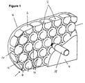
- an exemplary armor plate consists of a plurality of ceramic pellets 2 which are embedded within a solidified material 4.
- a ceramic pellet 2 of the type used in the armor plate shown in figure 1 is seen in more detail in figure 2a .
- the ceramic pellet 2 shown in figure 2a has a cylindrical body portion 6 which has two planar opposite ends 8 and a cylindrical surface 10.
- the body portion 6 has a length which is the distance along the cylindrical axis between the two ends 8, and which is represented in figure 2a by the letter H.
- a respective convexly curved end portion 12 extends from each end 8 of the body portion 6.
- Each convexly curved end portion 12 has the form of a segment of a sphere and has a base which lies adjacent to the body portion 6 and which has a diameter which is equal to the diameter of the body portion 6.
- Ceramic pellets 2 of the type described above are conveniently formed as a unitary body by pressing and methods for manufacturing such pellets are well known in the art.
- the ceramic pellet 2 can be made from any suitable ceramic material, and is preferably made from one of the ceramic materials discussed above.
- the ceramic pellets 2 are arranged in a single layer which is one pellet thick.
- the ceramic pellets 2 are arranged so that the cylindrical axes of the pellets 2 lie substantially parallel to one another.
- each ceramic pellet 2 has a respective convexly curved end portion 12 at each end.
- convexly curved end portions 12 are found at both sides of the armor plate.
- the ceramic pellets 2 need only have a single convexly curved end portion 12.
- the ceramic pellets 2 will be arranged so that the convexly curved end portions 12 are located at one side of the armor plate, and this side will be in impact receiving side of the armor plate.
- the ceramic pellets 2 are arranged so that each body portion 6 (other than the body portions 6 of the ceramic pellets 2 which lie at the edge of the armor plate) is either in contact with, or lies closely adjacent to the respective body portions 6 of six adjacent ceramic pellets 2. As discussed above, whereas direct contact between the body portions 6 is preferred, this cannot always be obtained in practice. For those ceramic pellets 2 which lie at the edge of the armor plate, each body portion 6 lies in contact with, or closely adjacent to the body portions of four adjacent ceramic pellets 2.
- each valley 14 is found between each three adjacent ceramic pellets 2.
- the valleys 14 pass across the layer of ceramic pellets.
- each valley 14 has, in cross section, a shape which is generally triangular, with each side of the triangle being concavely curved. This is because, of course, each valley 14 is formed between the cylindrical surfaces 10 of the body portions 6 of the three adjacent ceramic pellets 2.
- the valleys 14 will have different shapes.
- the shape of the valleys 14 can vary depending upon the shape of the body portions 6 of the ceramic pellets 2.
- the size of each valley 14 is defined with respect to the largest imaginary circle 16 which can fit within the valley 14, between the neighbouring body portions 6, and lying substantial perpendicularly to the axes of the neighbouring body portions 6.
- Such an imaginary circle 16, having a diameter d, is shown in the valley 14 in figure 2c .
- the ceramic pellets 2 are embedded in a solidified material 4, which can be any suitable solidified material, and is preferably one of the solidified materials mentioned above.
- the solidified material 4 passes through the valleys 14 and covers the ceramic pellets 2 on either side of the armor plate.
- the solidified material is generally slightly elastic so that when the armor plate is impacted by a projectile, the armor plate flexes slightly.
- the armor plate is tailored to be particularly effective against a 7.62 mm calibre projectile 18 having a predetermined projectile length. As seen in figure 2b , the projectile length is the entire length of the projectile 16 (but not including any casing).
- the size and shape of the ceramic pellets 2 are chosen so as to give the body portion length H and the diameter d of the largest imaginary circle 16 specific dimensions relative to the projectile 18, the armor plate is particularly effective at protecting against a projectile 18 of that length.
- the size and shape of the ceramic pellets 2 should ideally be chosen so that the body portion length is from 17% to 29% of the projectile length, and the diameter of the largest imaginary circle 16 is from 6% to 10% of the projectile length.
- the body portion length when the projectile length is 35mm, the body portion length may be from 5.95mm to 10.15mm, and the diameter of the largest imaginary circle 16 may be from 2.1mm to 3.5mm. It is also possible to calculate the body portion length and the diameter of the largest imaginary circle 16 based on an anticipated range of projectile length. For example, when the projectile length is anticipated to be from 32.8mm to 37mm, the diameter of the largest imaginary circle 16 will be from 1.96mm to 3.70mm, and the body portion length will be form 5.57mm to 10.73mm.
- the armor plate is used to protect against a projectile of the pre-determined length.
- the armor plate absorbs and dissipates kinetic energy from the projectile, and the projectile is shattered into fragments. It will be noted that the armor plate does not necessarily prevent penetration of the projectile on its own.
- the armor plate will generally be used in combination with the second layer, as discussed above. The second layer serves to catch and retain fragments of the projectile and to absorb the remaining kinetic energy of the fragments.
Landscapes
- Engineering & Computer Science (AREA)
- General Engineering & Computer Science (AREA)
- Chemical & Material Sciences (AREA)
- Ceramic Engineering (AREA)
- Aiming, Guidance, Guns With A Light Source, Armor, Camouflage, And Targets (AREA)
Applications Claiming Priority (2)
| Application Number | Priority Date | Filing Date | Title |
|---|---|---|---|
| IL188051A IL188051A0 (en) | 2007-12-11 | 2007-12-11 | Composite armor plate |
| IL191299A IL191299A0 (en) | 2008-05-07 | 2008-05-07 | Composite armor plate and method for using the same |
Publications (2)
| Publication Number | Publication Date |
|---|---|
| EP2071272A2 true EP2071272A2 (de) | 2009-06-17 |
| EP2071272A3 EP2071272A3 (de) | 2012-11-21 |
Family
ID=40306636
Family Applications (1)
| Application Number | Title | Priority Date | Filing Date |
|---|---|---|---|
| EP08253752A Withdrawn EP2071272A3 (de) | 2007-12-11 | 2008-11-18 | Verbundstoffpanzerplatte und Verwendungsverfahren dafür |
Country Status (2)
| Country | Link |
|---|---|
| US (1) | US20090145289A1 (de) |
| EP (1) | EP2071272A3 (de) |
Cited By (3)
| Publication number | Priority date | Publication date | Assignee | Title |
|---|---|---|---|---|
| EP2363682A3 (de) * | 2010-03-05 | 2013-10-30 | Krauss-Maffei Wegmann GmbH & Co. KG | Verfahren zur Instandsetzung eines Verbundpanzerungselements sowie Reparatur-Set zur Durchführung der Instandsetzung |
| PL424443A1 (pl) * | 2018-01-31 | 2019-08-12 | Instytut Technologii Bezpieczeństwa MORATEX | Sposób wykonania elastycznego pancerza balistycznego oraz pancerz wykonany tym sposobem |
| CN110270686A (zh) * | 2018-11-22 | 2019-09-24 | 无锡银邦防务科技有限公司 | 一种钛合金/陶瓷复合材料及制备方法 |
Families Citing this family (6)
| Publication number | Priority date | Publication date | Assignee | Title |
|---|---|---|---|---|
| US20120312150A1 (en) * | 2005-06-21 | 2012-12-13 | United States Govemment, as represented by the Secretary of the Navy | Body armor of ceramic ball embedded polymer |
| US8701540B2 (en) * | 2006-02-03 | 2014-04-22 | Lockheed Martin Corporation | Armor and method of making same |
| IL182511A (en) * | 2007-04-12 | 2014-07-31 | Yoav Hirschberg | Semi-finished protective layer, method of manufacture and a protective panel produced from it |
| US9347746B1 (en) * | 2008-01-03 | 2016-05-24 | Great Lakes Armor Systems, Inc. | Armored energy-dispersion objects and method of making and using |
| IL191258A0 (en) * | 2008-05-05 | 2009-05-04 | Gigi Simovich | Composite ballistic ceramic armor and method for making the same |
| ITUB20151170A1 (it) * | 2015-05-28 | 2016-11-28 | Elet Ca S R L Con Socio Unico | Struttura di protezione antiproiettile e corrispondente giubbotto antiproiettile |
Citations (19)
| Publication number | Priority date | Publication date | Assignee | Title |
|---|---|---|---|---|
| GB1081464A (en) | 1963-08-06 | 1967-08-31 | Feldmuehle Ag | Armour plate |
| GB1352418A (en) | 1971-05-11 | 1974-05-08 | Feldmuehle Anlagen Prod | Armour plate |
| US4061815A (en) | 1967-10-26 | 1977-12-06 | The Upjohn Company | Novel compositions |
| US4529640A (en) | 1983-04-08 | 1985-07-16 | Goodyear Aerospace Corporation | Spaced armor |
| US4836084A (en) | 1986-02-22 | 1989-06-06 | Akzo Nv | Armour plate composite with ceramic impact layer |
| US4868040A (en) | 1988-10-20 | 1989-09-19 | Canadian Patents & Development Limited | Antiballistic composite armor |
| GB2272272A (en) | 1992-11-10 | 1994-05-11 | T & N Technology Ltd | Armour |
| US5361678A (en) | 1989-09-21 | 1994-11-08 | Aluminum Company Of America | Coated ceramic bodies in composite armor |
| FR2711782A1 (fr) | 1991-07-30 | 1995-05-05 | Creusot Loire | Elément de blindage comportant un réseau de particules en matériau dur et procédé de réalisation de cet élément de blindage. |
| WO1998015796A1 (en) | 1996-10-09 | 1998-04-16 | Goodanew, Martin, Eric | Ceramic bodies for use in composite armor |
| EP0843149A1 (de) | 1996-11-12 | 1998-05-20 | Mofet Etzion | Verbundpanzerplatte und Verfahren zur Herstellung |
| US5763813A (en) | 1996-08-26 | 1998-06-09 | Kibbutz Kfar Etzion | Composite armor panel |
| WO1999060327A1 (en) | 1998-05-19 | 1999-11-25 | Michael Cohen | Composite armor plate |
| US6112635A (en) | 1996-08-26 | 2000-09-05 | Mofet Etzion | Composite armor panel |
| US6203908B1 (en) | 1996-08-26 | 2001-03-20 | Michael Cohen | Composite armor |
| US6289781B1 (en) | 1996-08-26 | 2001-09-18 | Michael Cohen | Composite armor plates and panel |
| US6408734B1 (en) | 1998-04-14 | 2002-06-25 | Michael Cohen | Composite armor panel |
| US6497966B2 (en) | 2001-01-15 | 2002-12-24 | Michael Cohen | Laminated armor |
| EP1521051A1 (de) | 2003-10-02 | 2005-04-06 | Michael Cohen | Keramikkörper für Panzerplatte |
Family Cites Families (3)
| Publication number | Priority date | Publication date | Assignee | Title |
|---|---|---|---|---|
| ATE370382T1 (de) * | 2001-07-25 | 2007-09-15 | Aceram Materials And Technolog | Keramische panzerungssysteme mit frontseitiger splitterfangschicht und dämpfungsschicht |
| US6635357B2 (en) * | 2002-02-28 | 2003-10-21 | Vladimir S. Moxson | Bulletproof lightweight metal matrix macrocomposites with controlled structure and manufacture the same |
| US7866248B2 (en) * | 2006-01-23 | 2011-01-11 | Intellectual Property Holdings, Llc | Encapsulated ceramic composite armor |
-
2008
- 2008-11-18 EP EP08253752A patent/EP2071272A3/de not_active Withdrawn
- 2008-12-11 US US12/333,183 patent/US20090145289A1/en not_active Abandoned
Patent Citations (20)
| Publication number | Priority date | Publication date | Assignee | Title |
|---|---|---|---|---|
| GB1081464A (en) | 1963-08-06 | 1967-08-31 | Feldmuehle Ag | Armour plate |
| US4061815A (en) | 1967-10-26 | 1977-12-06 | The Upjohn Company | Novel compositions |
| GB1352418A (en) | 1971-05-11 | 1974-05-08 | Feldmuehle Anlagen Prod | Armour plate |
| US4529640A (en) | 1983-04-08 | 1985-07-16 | Goodyear Aerospace Corporation | Spaced armor |
| US4836084A (en) | 1986-02-22 | 1989-06-06 | Akzo Nv | Armour plate composite with ceramic impact layer |
| US4868040A (en) | 1988-10-20 | 1989-09-19 | Canadian Patents & Development Limited | Antiballistic composite armor |
| US5361678A (en) | 1989-09-21 | 1994-11-08 | Aluminum Company Of America | Coated ceramic bodies in composite armor |
| FR2711782A1 (fr) | 1991-07-30 | 1995-05-05 | Creusot Loire | Elément de blindage comportant un réseau de particules en matériau dur et procédé de réalisation de cet élément de blindage. |
| GB2272272A (en) | 1992-11-10 | 1994-05-11 | T & N Technology Ltd | Armour |
| US6203908B1 (en) | 1996-08-26 | 2001-03-20 | Michael Cohen | Composite armor |
| US5763813A (en) | 1996-08-26 | 1998-06-09 | Kibbutz Kfar Etzion | Composite armor panel |
| US6112635A (en) | 1996-08-26 | 2000-09-05 | Mofet Etzion | Composite armor panel |
| US6289781B1 (en) | 1996-08-26 | 2001-09-18 | Michael Cohen | Composite armor plates and panel |
| US5972819A (en) | 1996-10-09 | 1999-10-26 | Cohen; Michael | Ceramic bodies for use in composite armor |
| WO1998015796A1 (en) | 1996-10-09 | 1998-04-16 | Goodanew, Martin, Eric | Ceramic bodies for use in composite armor |
| EP0843149A1 (de) | 1996-11-12 | 1998-05-20 | Mofet Etzion | Verbundpanzerplatte und Verfahren zur Herstellung |
| US6408734B1 (en) | 1998-04-14 | 2002-06-25 | Michael Cohen | Composite armor panel |
| WO1999060327A1 (en) | 1998-05-19 | 1999-11-25 | Michael Cohen | Composite armor plate |
| US6497966B2 (en) | 2001-01-15 | 2002-12-24 | Michael Cohen | Laminated armor |
| EP1521051A1 (de) | 2003-10-02 | 2005-04-06 | Michael Cohen | Keramikkörper für Panzerplatte |
Non-Patent Citations (1)
| Title |
|---|
| KO; SONG, CHARACTERIZATION OF MULTIFUNCTIONAL COMPOSITE ARMOR, 1996, pages 947 - 956 |
Cited By (4)
| Publication number | Priority date | Publication date | Assignee | Title |
|---|---|---|---|---|
| EP2363682A3 (de) * | 2010-03-05 | 2013-10-30 | Krauss-Maffei Wegmann GmbH & Co. KG | Verfahren zur Instandsetzung eines Verbundpanzerungselements sowie Reparatur-Set zur Durchführung der Instandsetzung |
| EP2363682B1 (de) | 2010-03-05 | 2019-09-04 | Krauss-Maffei Wegmann GmbH & Co. KG | Verfahren zur Instandsetzung eines Verbundpanzerungselements sowie Reparatur-Set zur Durchführung der Instandsetzung |
| PL424443A1 (pl) * | 2018-01-31 | 2019-08-12 | Instytut Technologii Bezpieczeństwa MORATEX | Sposób wykonania elastycznego pancerza balistycznego oraz pancerz wykonany tym sposobem |
| CN110270686A (zh) * | 2018-11-22 | 2019-09-24 | 无锡银邦防务科技有限公司 | 一种钛合金/陶瓷复合材料及制备方法 |
Also Published As
| Publication number | Publication date |
|---|---|
| EP2071272A3 (de) | 2012-11-21 |
| US20090145289A1 (en) | 2009-06-11 |
Similar Documents
| Publication | Publication Date | Title |
|---|---|---|
| EP1521051B1 (de) | Keramikkörper für Panzerplatte | |
| US7383762B2 (en) | Ceramic pellets and composite armor panel containing the same | |
| EP1510776B1 (de) | Verbundpanzerplatte | |
| US8281700B2 (en) | Composite armor plate and ceramic bodies for use therein | |
| EP1071916B1 (de) | Verbundpanzerplatte | |
| EP2071272A2 (de) | Verbundstoffpanzerplatte und Verwendungsverfahren dafür | |
| CA2479583C (en) | A composite armor plate and ceramic bodies for use therein | |
| US6575075B2 (en) | Composite armor panel | |
| US5763813A (en) | Composite armor panel | |
| EP0843149B1 (de) | Verbundpanzerplatte und Verfahren zur Herstellung | |
| US8402876B2 (en) | Ballistic lightweight ceramic armor with cross-pellets | |
| US20120186434A1 (en) | Ballistic Lightweight ceramic armor with resistant devices based on geometric shapes | |
| EP0942255B1 (de) | Verbundpanzerplatte | |
| EP1400775B1 (de) | Keramikkörper und ballistische Panzerplatte die derartige Körper enthält | |
| EP1707913B1 (de) | Keramisches Panzerelement für Panzerung | |
| IL168029A (en) | Ceramic pellets and composite armor panel containing the same | |
| IL115045A (en) | Complex armor board |
Legal Events
| Date | Code | Title | Description |
|---|---|---|---|
| PUAI | Public reference made under article 153(3) epc to a published international application that has entered the european phase |
Free format text: ORIGINAL CODE: 0009012 |
|
| AK | Designated contracting states |
Kind code of ref document: A2 Designated state(s): AT BE BG CH CY CZ DE DK EE ES FI FR GB GR HR HU IE IS IT LI LT LU LV MC MT NL NO PL PT RO SE SI SK TR |
|
| AX | Request for extension of the european patent |
Extension state: AL BA MK RS |
|
| PUAL | Search report despatched |
Free format text: ORIGINAL CODE: 0009013 |
|
| AK | Designated contracting states |
Kind code of ref document: A3 Designated state(s): AT BE BG CH CY CZ DE DK EE ES FI FR GB GR HR HU IE IS IT LI LT LU LV MC MT NL NO PL PT RO SE SI SK TR |
|
| AX | Request for extension of the european patent |
Extension state: AL BA MK RS |
|
| RIC1 | Information provided on ipc code assigned before grant |
Ipc: F41H 5/04 20060101AFI20121016BHEP |
|
| 17P | Request for examination filed |
Effective date: 20130521 |
|
| AKX | Designation fees paid |
Designated state(s): AT BE BG CH CY CZ DE DK EE ES FI FR GB GR HR HU IE IS IT LI LT LU LV MC MT NL NO PL PT RO SE SI SK TR |
|
| STAA | Information on the status of an ep patent application or granted ep patent |
Free format text: STATUS: THE APPLICATION IS DEEMED TO BE WITHDRAWN |
|
| 18D | Application deemed to be withdrawn |
Effective date: 20130522 |