EP2071288A1 - Procédé destiné à la sélection d'une zone de représentation à partir d'une représentation de carte bidimensionnelle - Google Patents
Procédé destiné à la sélection d'une zone de représentation à partir d'une représentation de carte bidimensionnelle Download PDFInfo
- Publication number
- EP2071288A1 EP2071288A1 EP08105565A EP08105565A EP2071288A1 EP 2071288 A1 EP2071288 A1 EP 2071288A1 EP 08105565 A EP08105565 A EP 08105565A EP 08105565 A EP08105565 A EP 08105565A EP 2071288 A1 EP2071288 A1 EP 2071288A1
- Authority
- EP
- European Patent Office
- Prior art keywords
- display
- display area
- selection
- display areas
- dimensional map
- Prior art date
- Legal status (The legal status is an assumption and is not a legal conclusion. Google has not performed a legal analysis and makes no representation as to the accuracy of the status listed.)
- Withdrawn
Links
- 238000000034 method Methods 0.000 title claims abstract description 19
- 238000012790 confirmation Methods 0.000 claims description 6
- 230000008859 change Effects 0.000 description 6
- 230000008901 benefit Effects 0.000 description 4
- 230000006870 function Effects 0.000 description 3
- 230000001419 dependent effect Effects 0.000 description 2
- 230000009471 action Effects 0.000 description 1
- 235000013410 fast food Nutrition 0.000 description 1
- 230000008569 process Effects 0.000 description 1
Images


Classifications
-
- G—PHYSICS
- G01—MEASURING; TESTING
- G01C—MEASURING DISTANCES, LEVELS OR BEARINGS; SURVEYING; NAVIGATION; GYROSCOPIC INSTRUMENTS; PHOTOGRAMMETRY OR VIDEOGRAMMETRY
- G01C21/00—Navigation; Navigational instruments not provided for in groups G01C1/00 - G01C19/00
- G01C21/26—Navigation; Navigational instruments not provided for in groups G01C1/00 - G01C19/00 specially adapted for navigation in a road network
- G01C21/34—Route searching; Route guidance
- G01C21/36—Input/output arrangements for on-board computers
- G01C21/3679—Retrieval, searching and output of POI information, e.g. hotels, restaurants, shops, filling stations, parking facilities
-
- G—PHYSICS
- G01—MEASURING; TESTING
- G01C—MEASURING DISTANCES, LEVELS OR BEARINGS; SURVEYING; NAVIGATION; GYROSCOPIC INSTRUMENTS; PHOTOGRAMMETRY OR VIDEOGRAMMETRY
- G01C21/00—Navigation; Navigational instruments not provided for in groups G01C1/00 - G01C19/00
- G01C21/38—Electronic maps specially adapted for navigation; Updating thereof
- G01C21/3863—Structures of map data
- G01C21/387—Organisation of map data, e.g. version management or database structures
- G01C21/3881—Tile-based structures
Definitions
- the invention is based on a method and a driver information device according to the preamble of the independent claims.
- a navigation device is already known in which a vehicle position is determined and a map section of a map is determined as a function of the determined vehicle position, which is then displayed by an output unit. Furthermore, it is known to assign a scale order to a driver information, so that a scale of a map section is selected as a function of the scale order.
- the method according to the invention with the features of the independent claim for selecting a display area from a two-dimensional map display has the advantage that in an operating mode a selection of a display area by a user is limited to a selection from a first set of display areas. This is advantageous since a selection of a display area by a user is restricted to a first set of display areas which have particular relevance for the user.
- the subdivision of the two-dimensional map representation into display areas is a tiling. This is advantageous since, given a subdivision of the two-dimensional map representation into at least two tiles, which in turn are two-dimensional display areas, each point of the two-dimensional map representation is assigned exactly to one tile.
- the selection of a display area is displayed to the user by a first graphical identifier. This is advantageous because the user is informed by the first graphical identifier which display area is currently selected by him.
- presentation areas of the first set are presentation areas which contain a representation of the travel route. This is advantageous since display areas which contain a representation of a route are display areas which have a higher relevance for the user with regard to their information content than display areas which do not include a display of the route.
- presentation areas of the first set are display areas, by means of which a symbol along the travel route is displayed. This is advantageous because information can be stored based on symbols along the route, which draw the driver's attention to special circumstances along the route.
- the selection is made by the user based on a direction in one of the directions below, above, right and left. This is advantageous because it is a common action for users of driver information facilities, based on such direction information a selection of To perform display areas on a two-dimensional map display.
- display areas of the first set are displayed by a second graphical identifier different from display areas of the second set.
- the second graphical identification draws the driver's attention to the display areas of the first set, to which a selection in the display area is restricted, so that he can easily associate which display areas are selectable for him.
- the user makes an acknowledgment of the selection of a presentation area by an input, so that on the basis of the confirmation information is displayed to the user which is linked to the selected presentation area.
- This is advantageous because the user gets further information displayed by confirming the selection of a display area, which were not previously displayed in the course of the display of the two-dimensional map display.
- the information is an enlarged representation of the selected display area. This is advantageous because the user can thus select a map section of the two-dimensional map display, in order to enlarge it and thus make it more visible.
- a driver information device has a display unit which carries out a display of a two-dimensional map representation in such a way that the two-dimensional map representation is subdivided into display areas, wherein the display unit divides the display areas into a first set and a second set of display areas depending on the travel route for selecting a display area from the two-dimensional map representation by a user, the display unit having a first interface via which it is connected to a data bus, wherein the operating unit has a second interface, via which it is connected to the data bus, characterized in that in an operating mode, the selection of a display area by the user is limited to a selection from the first set of display areas.
- the driver information device is characterized in that the operating device has a cross-type rocker, a keypad, a trackball or a joystick. This is advantageous since users of driver information facilities are accustomed to make inputs based on such controls an operating device.
- the driver information device has the advantages of the method according to the invention.
- FIG. 1 shows a two-dimensional map representation, which is divided into different display areas, according to an embodiment of the invention.
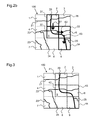
- FIG. 2a showed a two-dimensional map display, in which a selected display area is marked graphically.
- FIG. 2n shows a two-dimensional map representation in which different display areas are selected by the user and therefore marked graphically.
- FIG. 3 shows a two-dimensional map display in which display areas of the first set are displayed together with a second graphical marking.
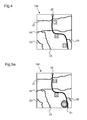
- FIG. 4 shows a two-dimensional map display, in which display areas of the first set are display areas, based on which a symbol along the route is displayed.
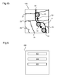
- FIG. 5a . 5b show two-dimensional map representations in which display areas, in the form of symbols along the route, which are selected by the user, are displayed graphically marked.
- FIG. 6 shows information that is displayed to the user on the basis of a confirmation and which are linked to the selected display area.
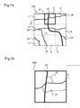
- Figure 7a, 7b show a process of selecting a display area from a two-dimensional map display and an enlarged view of the selected display area.
- FIGS. 8a, 8b, 8c each show a driver information device according to different embodiments of the invention.
- two-dimensional map representations include a representation of a route. It is also known to subdivide the two-dimensional map representation into display areas. According to the invention, the display areas of the two-dimensional map display are divided into a first set and a second set of display areas depending on the route.
- the method according to the invention is characterized in that, in an operating mode, a selection of a display area by a user is restricted to a selection from the first set of display areas. By such a restriction, there is the advantage that a user can select only those display areas that have particular relevance for him.
- FIG. 1 shows a two-dimensional map representation 100, which includes a representation of a route 20.
- the two-dimensional map display 100 is divided into nine display areas 1,..., 9.
- the two-dimensional map representation 100 preferably has a shape of a square according to the exemplary embodiment.
- the nine display areas 1 to 9 also each have the shape of a square.
- the subdivision of the two-dimensional map representation 100 is a tiling, for which reason the two-dimensional map representation 100 is divided into three lines lying one below the other, each of three display areas.
- the first three display areas 1 to 3 are located in the top row from left to right.
- the display areas 4 to 6 are located in the middle row from left to right.
- the display areas 7 to 9 are in the bottom row.
- a tiling in the mathematical sense a subdivision of a two-dimensional plane into sub-areas, also called tiles, where each point of the two-dimensional plane belongs to at least one tile. No point in the plane lies inside two or more tiles. Furthermore, different tiles have at most edge points in common.
- the nine display areas 1 to 9 are shown separated from each other by dashed lines.
- the two-dimensional map display 100 has a travel route 20 which runs along the second display area 2, the fifth display area 5, the sixth display area 6 and the ninth display area 9. Furthermore, a route route 21 extends along the first display area 1 to the second display area 2 and then further to the third display area 3. A second route 22 extends along the fourth display area 4 to the fifth display area 5 and then further to the sixth display area 6, which is in the fifth display area 5 the route 20 crosses. In the fourth display area 4, a fourth branches off from the second route 22 Route 24, which extends from the fourth display area 4 to the seventh display area 7 and then on to the eighth display area 8. Further, a third route route 23 passes through the seventh display area 7 without crossing another route route. It runs in the ninth display area 9, a fifth route route 25 branches off from the route 20 to the right edge of the ninth display area. 9
- the display areas 1 to 9 are divided into a first set and a second set of display areas as a function of the travel route 20. This division preferably takes place in such a way that those display areas through which the travel route 20 runs form the first set of display areas.
- the first set of areas of the first set and the second display area 2, the fifth display area 5, the sixth display area 6 and the ninth display area 9 are all the other display areas.
- all other display areas represent the second set of display areas.
- the selection of a display area by a user is limited to a selection of the first set of display areas.
- the selection of a display area in an operating mode by a user is thus limited to a selection of the second display area 2, the fifth display area 5, the sixth display area 6 or the ninth display area 9.
- the selection of a presentation area is indicated to the user by a first graphical identifier.
- a first graphical identifier there is an embodiment in FIG. 2a .
- FIG. 2a shows the two-dimensional map representation 100 together with all other presentation elements, as already described FIG. 1 explained. Additionally points FIG. 2a a graphical identification of the second display area 2 in the form of a rectangular frame 31. According to the exemplary embodiment, this frame 31 indicates to the user that the second display area 2 is selected.
- the first graphical marking of the selected display area preferably takes place by means of a rectangular frame 31. Further forms of graphic identification of a display area are conceivable. For example, it is possible to make the first graphical marking of a selected display area by making the selected display area brighter than non-selected display areas. Furthermore, it is possible for a selected display area 2 to be displayed with a higher driving intensity than non-selected display areas.
- the selection of a display area by the user is based on a direction in one of the directions below, above, right and / or left.
- FIG. 2b contains all presentation elements already in FIG. 1 are shown. More display elements FIG. 2b will be explained in more detail below.
- the second display area 2 is selected, which is indicated by a border 31 of the second display area 2. Due to an indication of direction by the user in the form of a downward direction, the fifth display area 5 is selected at a second time.
- the change of the selection of a display area from the second display area 2 to the fifth display area 5 is according to FIG.
- the user changes the selection from the fifth display area 5 to the sixth display area 6.
- This change of the selected display area is in the FIG. 2b is symbolized by an arrow 62 pointing from the fifth display area 5 to the sixth display area 6.
- This selection of the sixth display area 6 is displayed according to the exemplary embodiment by a border 33 of the sixth display area 6.
- a selection of the ninth display area 9 at a fourth time point by indicating the direction in the downward direction.
- the change from a selection of the sixth display area 6 to a selection of the ninth display area 9 is according to FIG. 2b symbolized by an arrow 63 which points from the sixth display area 6 to the ninth display area 9.
- a selection of the ninth display area 9 at the fourth time point is indicated by a border 34 of the ninth display area 9.
- the borders 31, 32, 33, 34 of the selectable display areas 2, 5, 6, 9 from the first set of display areas are respectively displayed only at the times at which a corresponding display area 2, 5, 6, 9 is also selected.
- the border 34 is displayed as the first graphic marking.
- FIG. 3 shows a two-dimensional map representation 100, which includes all display elements as already in accordance with FIG. 1 explained.
- FIG. 3 a second graphical marking of display areas of the first set such that display areas of the first set are displayed differently to display areas of the second set.
- FIG. 3 2 shows the two-dimensional map representation 100 in addition to the presentation elements of FIG. 1 a second graphical marking of the second display area 2, the fifth display area 5, the sixth display area 6 and the ninth display area 9.
- the second graphical identification of the display areas 2, 5, 6, 9 of the first set is carried out according to the exemplary embodiment in FIG FIG. 3 based on a dashed border 41, 42, 43, 44 of the respective display areas 2, 5, 6, 9 of the first set.
- the user receives a graphical indication of which display areas can be selected by him.
- the second graphic designation of the selectable display areas can be done by different graphic markings. Such second graphic markings are advantageously carried out on the basis of a border of display areas of the first set.
- a second graphical identification of display areas of the first set is carried out by a display with greater brightness than is done for display areas of the second set.
- a variation of a contrast or a color intensity can be used.
- the first graphic designation of a selected display area and the second graphic designation of display areas of the first set are not mutually exclusive.
- this selection by an additional border 31 of the second display area 2 as in FIG. 2a is possible.
- Representation areas of the first set are preferably display areas, by means of which a symbol along the travel route 20 is displayed.
- An embodiment of this shows FIG. 4 , According to the embodiment in FIG. 4 indicates the two-dimensional map representation 100 the route 20 and the first to the fifth route route 21, ..., 25, which already according to FIG. 1 are described.
- the two-dimensional map representation 100 furthermore has a first symbol 11, a second symbol 12 and a third symbol 13.
- the symbols are rectangular areas which are arranged along the travel route 20.
- a representation of symbols in a two-dimensional map representation 100 along a route 20 is known to the person skilled in the art.
- Symbols 11 through 13 represent the first set of display areas to which user selection is restricted in one mode of operation.
- the symbols 11 to 13 are preferably symbols which are intended to alert a user to certain devices which are located along the route 20. Such devices are for example so-called points of interest.
- a point of interest may be, for example, a gas station, a rest stop, a fast food restaurant, a motorway exit or similar facilities.
- FIG. 5a . 5b show an exemplary embodiment for selecting a display area from a two-dimensional map display 100, in which the display areas of the first set are symbols 11, 12, 13 along a travel route 20.
- FIG. 5a shows the two-dimensional map display 100 with all presentation elements as already in FIG. 4 explained.
- the first symbol 11 is selected.
- the selection of the first icon 11 as a display area from the first set of display areas is indicated by a first graphical identifier 51.
- the first graphical identifier 51 is a star shape that extends around the first symbol 11.
- FIG. 5b a direction input of the user took place, as a result of which the selection changes from the first symbol 11 to the second symbol 12 at a second time.
- This change of the display area from the first set is indicated by an arrow 71 in the FIG. 5b symbolizing which points from the first symbol 11 to the twelfth symbol 12.
- the second graphic designation changes from the graphic designation 41 of the first symbol to the graphic designation 42 of the second symbol 12.
- the second symbol 12 is selected for a second point. Due to a further direction input by the user, the selection of a display area from the first set changes from the second icon 12 to the third icon 13.
- the third icon 13 is selected, which is indicated by a second graphical identifier 43 is displayed in star form around the third symbol 13 around.
- the change of selection from the second symbol 12 to the third symbol 13 is in FIG. 5b symbolized by an arrow 72 from the second symbol 12 to the third symbol 13.
- a direction indication for the selection of a display area by the user takes place using one of the directions below, above, right and / or left.
- a direction indication is preferably carried out by a cross-rocker, a keypad, a trackball or a joystick.
- the directional indication made by the user is not necessarily limited to one of the above-mentioned directions.
- a selection of a display area is based on a cursor, which is moved by means of one of the aforementioned input means on the display of the two-dimensional map display, so that by pressing a button or a button, a selection of a display area is made, on which the cursor points.
- the user makes an acknowledgment of the selection of a display area by an input, and that on the basis of the confirmation information is displayed to the user which is linked to the selected display area.
- An illustration of information 400 which is linked to a symbol, is displayed. Is, for example, according to the embodiment in FIG. 5a
- the user is informed according to the embodiment of information 400.
- An illustration of information 400 takes place, for example, in the form of three text fields 401, 402, 403, which lie below one another, for example. In such text fields 401 to 403, it is possible to display information about a device to the user, such as an address of a device, pricing information, a telephone number or other information.
- the user makes an input confirmation of the selection of a display area, so that the user information is displayed, which is an enlarged view of the selected display area.
- Figure 7a shows a two-dimensional map display 100, which has all the display elements, as already in accordance with FIG. 2a explained.
- the second display area 2 is selected and preferably characterized by a first graphic marking in the form of a border 31 of the second display area 2.
- the user confirms the selection of the selected display area 2.
- the display changes based on the confirmation of a display as in Figure 7a presented to an ad as in FIG. 7b shown.
- FIG. 7b FIG. 10 shows an enlarged two-dimensional map representation 300, which represents an enlargement of the selected second representation area 2.
- the enlarged two-dimensional map representation 300 has the travel route 20 and the first route route 21. Due to the enlarged two-dimensional map display 300 of the selected display area 2, further route routes are preferably displayed in the two-dimensional map display 300, which is shown in FIG Figure 7a not shown.
- the enlarged two-dimensional map representation 300 includes a sixth route 26, which represents a connection of the route 20 and the first route route 21, and a seventh route route 27, which branches off from the first route route 21 and subsequently crosses the second route route 20.
- a sixth route 26 which represents a connection of the route 20 and the first route route 21, and a seventh route route 27, which branches off from the first route route 21 and subsequently crosses the second route route 20.
- FIGS. 8a, 8b, 8c show embodiments of the driver information device according to the invention.
- the driver information device 3000 has a display unit 1001, which is connected to a data bus 2000 via a first interface 1011. Furthermore, the driver information device 3000 has an operating unit 1002, which is likewise connected to the data bus 2000 via a second interface 1012.
- the display unit 1001 displays a two-dimensional map display such that the two-dimensional map representation is divided into display area.
- the display unit divides the display areas depending on the route into a first set and a second set of display areas.
- the user selects a display area from the two-dimensional map display. In an operating mode, the selection of a display area by the user is limited to a selection from the first set of display areas.
- the operating device 1002 preferably has a cross-type rocker, a keypad, a trackball or a joystick. Using these controls, the user selects display areas. Further, the user preferably uses these controls to make inputs.
- FIG. 8b another embodiment of the driver information device 3002 is shown.
- This has the display unit 1001, a computing unit 1100 and map data 1300 on.
- the map data 1300 is preferably stored in a memory unit.
- the display unit 1001 creates a two-dimensional map representation using the arithmetic unit 1100 and the map data 1300.
- the prerequisite for this is that a route is already established.
- a determination of a route in dependence on an input of a user is known to the person skilled in the art.
- FIG. 8c a further embodiment of the driver information device 3003 is shown.
- the computing unit 1100 is designed as a separate unit, which is connected to the data bus 2000 via a third interface 1013.
- the embodiment in FIG. 8c a separate memory unit 1200 in which the map data 1300 are stored.
- the separate memory unit 1200 is connected to the data bus 2000 via a fourth interface 1014. Via the data bus 2000, the units mentioned communicate with the display unit 1001 and the operating unit 1002.
- the driver information device is designed to carry out one of the methods which are described with regard to a selection of a display area of a two-dimensional map display.
Landscapes
- Engineering & Computer Science (AREA)
- Radar, Positioning & Navigation (AREA)
- Remote Sensing (AREA)
- Automation & Control Theory (AREA)
- Physics & Mathematics (AREA)
- General Physics & Mathematics (AREA)
- Databases & Information Systems (AREA)
- Navigation (AREA)
- User Interface Of Digital Computer (AREA)
Applications Claiming Priority (1)
| Application Number | Priority Date | Filing Date | Title |
|---|---|---|---|
| DE102007060055A DE102007060055A1 (de) | 2007-12-13 | 2007-12-13 | Verfahren zur Auswahl eines Darstellungsbereiches aus einer zweidimensionalen Kartendarstellung |
Publications (1)
| Publication Number | Publication Date |
|---|---|
| EP2071288A1 true EP2071288A1 (fr) | 2009-06-17 |
Family
ID=40428102
Family Applications (1)
| Application Number | Title | Priority Date | Filing Date |
|---|---|---|---|
| EP08105565A Withdrawn EP2071288A1 (fr) | 2007-12-13 | 2008-10-14 | Procédé destiné à la sélection d'une zone de représentation à partir d'une représentation de carte bidimensionnelle |
Country Status (2)
| Country | Link |
|---|---|
| EP (1) | EP2071288A1 (fr) |
| DE (1) | DE102007060055A1 (fr) |
Cited By (1)
| Publication number | Priority date | Publication date | Assignee | Title |
|---|---|---|---|---|
| US20240247947A1 (en) * | 2021-06-30 | 2024-07-25 | Huawei Technologies Co., Ltd. | Map display method, apparatus, and terminal device |
Citations (6)
| Publication number | Priority date | Publication date | Assignee | Title |
|---|---|---|---|---|
| DE19835422A1 (de) * | 1997-08-07 | 1999-02-11 | Aisin Aw Co | Kartenanzeigevorrichtung und Aufzeichnungsmedium |
| DE10016674A1 (de) | 2000-04-04 | 2001-10-18 | Bosch Gmbh Robert | Verfahren zur Ausgabe von Daten in einem Fahrzeug und Fahrerinformationsvorrichtung |
| US6401034B1 (en) * | 1999-09-02 | 2002-06-04 | Navigation Technologies Corp. | Method and system for finding intermediate destinations with a navigation system |
| WO2005032177A1 (fr) * | 2003-10-01 | 2005-04-07 | Thinkware Systems Corporation | Procede et systeme permettant d'obtenir un service de recherche de donnees cartographiques |
| US20050261830A1 (en) * | 2004-05-19 | 2005-11-24 | Honda Motor Co., Ltd. | Method for modifying navigation information |
| US7133771B1 (en) * | 2002-08-29 | 2006-11-07 | America Online, Inc. | Automated route determination to avoid a particular maneuver |
-
2007
- 2007-12-13 DE DE102007060055A patent/DE102007060055A1/de not_active Withdrawn
-
2008
- 2008-10-14 EP EP08105565A patent/EP2071288A1/fr not_active Withdrawn
Patent Citations (6)
| Publication number | Priority date | Publication date | Assignee | Title |
|---|---|---|---|---|
| DE19835422A1 (de) * | 1997-08-07 | 1999-02-11 | Aisin Aw Co | Kartenanzeigevorrichtung und Aufzeichnungsmedium |
| US6401034B1 (en) * | 1999-09-02 | 2002-06-04 | Navigation Technologies Corp. | Method and system for finding intermediate destinations with a navigation system |
| DE10016674A1 (de) | 2000-04-04 | 2001-10-18 | Bosch Gmbh Robert | Verfahren zur Ausgabe von Daten in einem Fahrzeug und Fahrerinformationsvorrichtung |
| US7133771B1 (en) * | 2002-08-29 | 2006-11-07 | America Online, Inc. | Automated route determination to avoid a particular maneuver |
| WO2005032177A1 (fr) * | 2003-10-01 | 2005-04-07 | Thinkware Systems Corporation | Procede et systeme permettant d'obtenir un service de recherche de donnees cartographiques |
| US20050261830A1 (en) * | 2004-05-19 | 2005-11-24 | Honda Motor Co., Ltd. | Method for modifying navigation information |
Cited By (1)
| Publication number | Priority date | Publication date | Assignee | Title |
|---|---|---|---|---|
| US20240247947A1 (en) * | 2021-06-30 | 2024-07-25 | Huawei Technologies Co., Ltd. | Map display method, apparatus, and terminal device |
Also Published As
| Publication number | Publication date |
|---|---|
| DE102007060055A1 (de) | 2009-06-18 |
Similar Documents
| Publication | Publication Date | Title |
|---|---|---|
| EP1378723B1 (fr) | Système d'information pour conducteurs | |
| DE10051680B4 (de) | Schema zur Darstellung mehrerer Druckauftragsabänderungselemente in einer Drucksoftware-Benutzerschnittstelle | |
| DE10126421B4 (de) | Fahrzeugrechner-System und Verfahren zur Steuerung eines Cursors für ein Fahrzeugrechner-System | |
| EP3036126B1 (fr) | Procédé pour opérer un dispositif d'opération et d'affichage dans un véhicule et dispositif d'opération et d'affichage dans un véhicule | |
| DE69609130T2 (de) | Umblätterapparat zur Anwendung mit einem Rechnersystem | |
| DE102010020895A1 (de) | Verfahren und Vorrichtung zum Bereitstellen einer Benutzerschnittstelle | |
| DE102007056328A1 (de) | Verfahren und Vorrichtung zum Bereitstellen einer Information über interessante Orte mit einem Navigationssystem | |
| EP2984453B1 (fr) | Méthode pour permettre la restitution et l'utilisation de groupes de poi | |
| EP2930051B1 (fr) | Dispositif et procédé de préparation d'une interface utilisateur graphique dans un véhicule | |
| DE102013006026A1 (de) | Orientierungszoom in Navigationskarten bei Darstellung auf kleinen Bildschirmen | |
| EP1214217B1 (fr) | Dispositif indicateur | |
| EP2050610B1 (fr) | Véhicule automobile | |
| EP1511972A1 (fr) | Procede d'entree de noms de localites | |
| EP1282854B1 (fr) | Procede et dispositif pour entrer une suite de caracteres | |
| DE69912272T2 (de) | Navigationssystem mit benutzerschnittstelle | |
| DE19941945C2 (de) | Verfahren und Vorrichtung zum Darstellen aktivierter Bedien- und Anzeigebereiche | |
| EP2718672A1 (fr) | Procédé et dispositif pour la préparation d'une interface utilisateur | |
| EP2071288A1 (fr) | Procédé destiné à la sélection d'une zone de représentation à partir d'une représentation de carte bidimensionnelle | |
| DE102007052297A1 (de) | Verfahren zum Betrieb eines Navigationssystems | |
| DE102005058145B4 (de) | Verfahren zur optischen Ausgabe einer Vielzahl von auswählbaren Zielbegriffen | |
| EP3364283A1 (fr) | Système d'exploitation, procédé de fonctionnement d'un système d'exploitation et véhicule doté d'un système d'exploitation | |
| EP1804026B1 (fr) | Procédé destiné à la sélection d'un emplacement | |
| DE102005019870A1 (de) | Informationssystem zur Bedienung elektronischer Geräte mit hierarchisch aufgebautem Bedienmenü | |
| WO2005064428A2 (fr) | Systeme de commande pour vehicule a moteur | |
| DE102015004367A1 (de) | Verfahren zum Steuern einer Funktion eines Kraftfahrzeugs |
Legal Events
| Date | Code | Title | Description |
|---|---|---|---|
| PUAI | Public reference made under article 153(3) epc to a published international application that has entered the european phase |
Free format text: ORIGINAL CODE: 0009012 |
|
| AK | Designated contracting states |
Kind code of ref document: A1 Designated state(s): AT BE BG CH CY CZ DE DK EE ES FI FR GB GR HR HU IE IS IT LI LT LU LV MC MT NL NO PL PT RO SE SI SK TR |
|
| AX | Request for extension of the european patent |
Extension state: AL BA MK RS |
|
| AKX | Designation fees paid | ||
| STAA | Information on the status of an ep patent application or granted ep patent |
Free format text: STATUS: THE APPLICATION IS DEEMED TO BE WITHDRAWN |
|
| 18D | Application deemed to be withdrawn |
Effective date: 20091218 |
|
| REG | Reference to a national code |
Ref country code: DE Ref legal event code: 8566 |