EP2071358A2 - Laserdistanzmesser - Google Patents
Laserdistanzmesser Download PDFInfo
- Publication number
- EP2071358A2 EP2071358A2 EP08105806A EP08105806A EP2071358A2 EP 2071358 A2 EP2071358 A2 EP 2071358A2 EP 08105806 A EP08105806 A EP 08105806A EP 08105806 A EP08105806 A EP 08105806A EP 2071358 A2 EP2071358 A2 EP 2071358A2
- Authority
- EP
- European Patent Office
- Prior art keywords
- receiving
- laser distance
- polarization
- distance meter
- photoreceiver
- Prior art date
- Legal status (The legal status is an assumption and is not a legal conclusion. Google has not performed a legal analysis and makes no representation as to the accuracy of the status listed.)
- Withdrawn
Links
- 230000003287 optical effect Effects 0.000 claims abstract 2
- 230000010287 polarization Effects 0.000 claims description 36
- 108091008695 photoreceptors Proteins 0.000 claims description 9
- 238000005259 measurement Methods 0.000 claims description 4
- 238000010276 construction Methods 0.000 description 2
- 239000013078 crystal Substances 0.000 description 2
- 239000011888 foil Substances 0.000 description 2
- 239000011248 coating agent Substances 0.000 description 1
- 238000000576 coating method Methods 0.000 description 1
- 238000011161 development Methods 0.000 description 1
- 230000018109 developmental process Effects 0.000 description 1
- 238000006073 displacement reaction Methods 0.000 description 1
- 238000003384 imaging method Methods 0.000 description 1
- 239000000463 material Substances 0.000 description 1
- 238000000034 method Methods 0.000 description 1
Images
Classifications
-
- G—PHYSICS
- G01—MEASURING; TESTING
- G01S—RADIO DIRECTION-FINDING; RADIO NAVIGATION; DETERMINING DISTANCE OR VELOCITY BY USE OF RADIO WAVES; LOCATING OR PRESENCE-DETECTING BY USE OF THE REFLECTION OR RERADIATION OF RADIO WAVES; ANALOGOUS ARRANGEMENTS USING OTHER WAVES
- G01S7/00—Details of systems according to groups G01S13/00, G01S15/00, G01S17/00
- G01S7/48—Details of systems according to groups G01S13/00, G01S15/00, G01S17/00 of systems according to group G01S17/00
- G01S7/499—Details of systems according to groups G01S13/00, G01S15/00, G01S17/00 of systems according to group G01S17/00 using polarisation effects
-
- G—PHYSICS
- G01—MEASURING; TESTING
- G01C—MEASURING DISTANCES, LEVELS OR BEARINGS; SURVEYING; NAVIGATION; GYROSCOPIC INSTRUMENTS; PHOTOGRAMMETRY OR VIDEOGRAMMETRY
- G01C3/00—Measuring distances in line of sight; Optical rangefinders
- G01C3/02—Details
- G01C3/06—Use of electric means to obtain final indication
- G01C3/08—Use of electric radiation detectors
-
- G—PHYSICS
- G01—MEASURING; TESTING
- G01S—RADIO DIRECTION-FINDING; RADIO NAVIGATION; DETERMINING DISTANCE OR VELOCITY BY USE OF RADIO WAVES; LOCATING OR PRESENCE-DETECTING BY USE OF THE REFLECTION OR RERADIATION OF RADIO WAVES; ANALOGOUS ARRANGEMENTS USING OTHER WAVES
- G01S17/00—Systems using the reflection or reradiation of electromagnetic waves other than radio waves, e.g. lidar systems
- G01S17/02—Systems using the reflection of electromagnetic waves other than radio waves
- G01S17/06—Systems determining position data of a target
- G01S17/08—Systems determining position data of a target for measuring distance only
-
- G—PHYSICS
- G01—MEASURING; TESTING
- G01S—RADIO DIRECTION-FINDING; RADIO NAVIGATION; DETERMINING DISTANCE OR VELOCITY BY USE OF RADIO WAVES; LOCATING OR PRESENCE-DETECTING BY USE OF THE REFLECTION OR RERADIATION OF RADIO WAVES; ANALOGOUS ARRANGEMENTS USING OTHER WAVES
- G01S17/00—Systems using the reflection or reradiation of electromagnetic waves other than radio waves, e.g. lidar systems
- G01S17/02—Systems using the reflection of electromagnetic waves other than radio waves
- G01S17/06—Systems determining position data of a target
- G01S17/08—Systems determining position data of a target for measuring distance only
- G01S17/10—Systems determining position data of a target for measuring distance only using transmission of interrupted, pulse-modulated waves
-
- G—PHYSICS
- G01—MEASURING; TESTING
- G01S—RADIO DIRECTION-FINDING; RADIO NAVIGATION; DETERMINING DISTANCE OR VELOCITY BY USE OF RADIO WAVES; LOCATING OR PRESENCE-DETECTING BY USE OF THE REFLECTION OR RERADIATION OF RADIO WAVES; ANALOGOUS ARRANGEMENTS USING OTHER WAVES
- G01S17/00—Systems using the reflection or reradiation of electromagnetic waves other than radio waves, e.g. lidar systems
- G01S17/02—Systems using the reflection of electromagnetic waves other than radio waves
- G01S17/06—Systems determining position data of a target
- G01S17/08—Systems determining position data of a target for measuring distance only
- G01S17/32—Systems determining position data of a target for measuring distance only using transmission of continuous waves, whether amplitude-, frequency-, or phase-modulated, or unmodulated
-
- G—PHYSICS
- G01—MEASURING; TESTING
- G01S—RADIO DIRECTION-FINDING; RADIO NAVIGATION; DETERMINING DISTANCE OR VELOCITY BY USE OF RADIO WAVES; LOCATING OR PRESENCE-DETECTING BY USE OF THE REFLECTION OR RERADIATION OF RADIO WAVES; ANALOGOUS ARRANGEMENTS USING OTHER WAVES
- G01S7/00—Details of systems according to groups G01S13/00, G01S15/00, G01S17/00
- G01S7/48—Details of systems according to groups G01S13/00, G01S15/00, G01S17/00 of systems according to group G01S17/00
- G01S7/481—Constructional features, e.g. arrangements of optical elements
- G01S7/4816—Constructional features, e.g. arrangements of optical elements of receivers alone
Definitions
- the invention refers to a manageable, electro-optical laser distance meter, preferably for use in the construction industry.
- a measuring accuracy in the mm range is needed.
- the mostly visible bundled light beam of a laser diode is sent to the surface of a measured object.
- the backscattered and / or reflected light is imaged by a receiving optics on the active surface of a photoreceiver.
- the modulation of the light determines the light transit time between the emission and the reception of the light.
- Modern such laser distance meter work with the so-called impulse backmixing method, to which the person skilled in the art with respect to the details DE10112833 is referenced.
- a large usable dynamic range is to be covered, because it should reflect both very weak, from large distances and from bad targets (eg black material) backscattered measuring light pulses as well as very strong, from the near range and on reflecting surfaces (painted surfaces, tiles) Measuring light pulses are detected.
- bad targets eg black material
- backscattered measuring light pulses as well as very strong, from the near range and on reflecting surfaces (painted surfaces, tiles) Measuring light pulses are detected.
- the planar photoreceiver is covered with an opaque diaphragm in such a way that two separate light-sensitive areas are formed.
- the laser diode usually emits linearly polarized light.
- the received light is also linearly polarized. If the surface is ideally scattered, unpolarized light is received.
- Partially reflecting surfaces produce, depending on the reflection properties, both scattering, unpolarized portions and reflected, polarized portions.
- the reflected portions which also appear in apparently pure scattering surfaces such as e.g. Concrete walls are present, advantageous amplifying measurement signal contributions.
- the reflected components in particular in the case of strongly reflecting surfaces, are very disturbing, since they lead to overloading of the photoreceiver.
- the object of the invention is to increase the usable dynamic range in manageable, electro-optical laser distance meters.
- an electro-optical laser distance meter has a manageable housing, an electrical beam source for generating a collimated light beam, a receiving optics with a receiving axis along the axis arranged in the focal point, transversely to the reception axis planar photoreceptor for receiving parts of the backscattered by a measurement object in a received beam, light beam the photoreceiver within the receiving beam is partially shadowed by a polarizing filter (eg formed as foil, layer system or crystal).
- a polarizing filter eg formed as foil, layer system or crystal
- the imaging properties for nearby targets are different from those of distant targets mapped along the receive axis at the focal point, much of the light incident on the photoreceiver along the receive axis is not shadowed by the polarizer.
- a large part of the light striking the planar photoreceiver is shaded by the polarization filter with respect to a polarization direction. Only the portion polarized according to the polarization direction of the polarizing filter can pass and reach the photoreceptor. Since strong, leading to overdriving, light signals are optically suppressed, the receiver can thus be designed much more sensitive, whereby the usable dynamic range is increased. This leads to an increase in the range and the ability to measure at close range on reflective surfaces.
- the polarization filter is impermeable parallel to the polarization of the beam source, whereby the intensive especially in the near field reflection on smooth measuring objects, in which the polarization of the light beam is maintained, additionally suppressed and thus the usable dynamic range is further increased.
- the polarization filter is arranged outside the receiving axis, whereby only a light near measuring objects is shaded with respect to a polarization direction at a receiving axis parallel to the receiving axis of the polarization filter.
- the polarization filter is advantageously a polarization layer which is arranged directly on or in a component of the receiving optics and which is furthermore advantageously applied to the receiving lens, as a result of which it is economically easy to produce.
- the polarizing filter is applied directly to the photoreceiver, whereby a fixed orientation of the polarizing filter is present to the photoreceiver.
- the photoreceiver has a diaphragm, further advantageously also as a directly applied coating, whereby additionally the photosensitive receiving surface area of the photoreceptor can be suitably fixed.
- the polarization filter is arranged within the receiving axis between the receiving lens and the focal point, whereby only a light near Doberteiler is shadowed with respect to a polarization direction at a coaxial to the transmitting axis receiving axis of the polarizing filter.
- the polarization filter is a polarization beam splitter, whereby a light beam emitted by the beam source can be coupled coaxially to the reception axis.
- a paraaxial electro-optical laser distance meter 1 comprises a handleable housing 2, an electric beam source 3 in the form of a laser diode for generating a modulated, linearly polarized, collimated and visible light beam 4 and a reception optics 5 arranged offset parallel thereto.
- an electric beam source 3 in the form of a laser diode for generating a modulated, linearly polarized, collimated and visible light beam 4 and a reception optics 5 arranged offset parallel thereto.
- a transversely to the receiving axis E area photoreceptor 7 in the form of a photodiode for receiving parts of the backscattered by a measuring object 8 in a receiving beam 9 light beam 4 is arranged.
- the photoreceiver 7 within the receiving beam 9 but outside the reception axis E is partially shadowed by a polarizing filter 10 which transmits only the polarized perpendicular to the polarization of the beam source 3 components of the light and thus suppresses the reflected (equal polarized) component.
- the polarizing filter 10 is applied directly to the receiving lens 11 in the form of a layer system. The majority of the receiving beam 9 of the far-field incident on the photosensitive receiving surface area of the photoreceptor 7 does not pass the polarizing filter 10, so that all the polarization components reach the photoreceiver 7.
- the receiving beam 9 of the near zone impinging on the light-sensitive receiving surface area of the photoreceiver 7 passes for the most part the polarization filter 10, so that only those not parallel to the beam source 3 (FIG. Fig. 1 ) polarized polarization components reach the photoreceiver 7 and thus the (on well reflective surfaces) reflected portion is substantially suppressed.
- the polarizing filter 10 ' is arranged in the form of a crystal between the receiving lens 11 and the photoreceiver 7.
- the polarizing filter 10 is disposed in the form of a film directly on the photosensitive receiving surface area of the photoreceptor 7.
- Fig. 5 is applied directly to the photoreceptor 7, an opaque aperture 12 with two openings 13a, 13b, which generates two separate, photosensitive receiving surface areas, wherein a first receiving area on the Reception axis E is located and the other second reception area is spaced therefrom.
- the first reception area is detected only by far-field light
- the second reception area is detected only by near-field light.
- the polarization filter 10 Only on the second reception area is the polarization filter 10 in the form of a foil.
- Fig. 6 has a coaxial electro-optical laser distance meter 1 'a manageable housing 2, an electric beam source 3 in the form of a laser diode for generating a modulated, linearly polarized, collimated and visible light beam 4, a receiving optics 5 arranged along the receiving axis E at the focal point 6, transverse to Reception axis E planar photoreceiver 7 in the form of a photodiode for receiving parts of the backscattered from a measurement object 8 in a receive beam 9 light beam 4.
- an electric beam source 3 in the form of a laser diode for generating a modulated, linearly polarized, collimated and visible light beam 4
- a receiving optics 5 arranged along the receiving axis E at the focal point 6, transverse to Reception axis E planar photoreceiver 7 in the form of a photodiode for receiving parts of the backscattered from a measurement object 8 in a receive beam 9 light beam 4.
- the photoreceiver 7 in the coaxial interior of the receiving beam 9 is partially shadowed by a polarization filter 10 "', which transmits only the components of the light polarized perpendicularly to the polarization of the beam source 3 and thus suppresses the reflected (equally polarized) component.
- a polarization beam splitter in the form of a polarization beam splitter is arranged axially between the focal point 6 and the receiving lens 11 and reflects the light beam 4 generated by the beam source 3 oriented transversely to the receiving axis E coaxially into the receiving axis E.
Landscapes
- Physics & Mathematics (AREA)
- Engineering & Computer Science (AREA)
- Electromagnetism (AREA)
- General Physics & Mathematics (AREA)
- Radar, Positioning & Navigation (AREA)
- Remote Sensing (AREA)
- Computer Networks & Wireless Communication (AREA)
- Optical Radar Systems And Details Thereof (AREA)
- Measurement Of Optical Distance (AREA)
Abstract
Description
- Die Erfindung bezeichnet einen handhabbaren, elektrooptischen Laserdistanzmesser, vorzugsweise zur Verwendung im Bauhilfsgewerbe.
- Bei im Bauhilfsgewerbe benutzten handhabbaren Laserdistanzmessern für einen messbaren Distanzbereich bis zu einigen 100m wird eine Messgenauigkeit im mm-Bereich benötigt. Dafür wird der zumeist sichtbare, gebündelte Lichtstrahl einer Laserdiode auf die Oberfläche eines Messobjektes geschickt. Das von dort zurückgestreute und / oder reflektierte Licht wird von einer Empfangsoptik auf die aktive Fläche eines Photoempfängers abgebildet. Über die Modulation des Lichts (impulsförmig, sinusförmig oder stochastisch) wird die Lichtlaufzeit zwischen dem Aussenden und dem Empfang des Lichtes ermittelt. Moderne derartige Laserdistanzmesser arbeiten mit dem sogenannten Impulsrückmischverfahren, wozu der interessierte Fachmann bezüglich Einzelheiten auf die
DE10112833 verwiesen wird. - Bei obigen Laserdistanzmessern ist ein grosser nutzbarer Dynamikbereich abzudecken, denn es sollen sowohl sehr schwache, aus grossen Entfernungen und von schlechten Zielen (z.B. schwarzer Stoff) zurückgestreute Messlichtimpulse als auch sehr starke, aus dem Nahbereich und an spiegelnden Oberflächen (lackierte Flächen, Fliesen) reflektierte Messlichtimpulse detektiert werden.
- Nach der
DE10051302 wird bei einem Laserdistanzmesser mit einem zur Empfängerachse versetzt angeordneten Lichtsender der flächige Photoempfänger mit einer lichtundurchlässigen Blende derart abgedeckt, dass zwei getrennte lichtempfindliche Bereiche ausgebildet sind. - Nach der
WO03002939 - Die Laserdiode sendet in der Regel linear polarisiertes Licht aus. Bei ideal reflektierenden Oberflächen ist das Empfangslicht ebenfalls linear polarisiert. Bei ideal streuender Oberfläche wird unpolarisiertes Licht empfangen. Teilweise reflektierende Oberflächen produzieren in Abhängigkeit von den Reflexionseigenschaften sowohl streuende, unpolarisierte Anteile als auch reflektierte, polarisierte Anteile. Bei weit entfernten Oberflächen liefern die reflektierten Anteile, welche auch bei scheinbar rein streuenden Oberflächen wie z.B. Betonwänden vorhanden sind, vorteilhafte verstärkende Messsignalbeiträge. Bei nahen Oberflächen sind die reflektierten Anteile insbesondere bei stark reflektierenden Flächen hingegen sehr störend, da sie zu einer Übersteuerung des Photoempfängers führen.
- Die Aufgabe der Erfindung besteht in der Erhöhung des nutzbaren Dynamikbereiches bei handhabbaren, elektrooptischen Laserdistanzmessern.
- Die Aufgabe wird im Wesentlichen durch die Merkmale des Anspruchs 1 gelöst. Vorteilhafte Weiterbildungen ergeben sich aus den Unteransprüchen.
- So weist ein elektrooptischer Laserdistanzmesser ein handhabbares Gehäuse, eine elektrische Strahlquelle zur Erzeugung eines gebündelten Lichtstrahls, eine Empfangsoptik mit einem längs der Empfangsachse im Brennpunkt angeordneten, quer zur Empfangsachse flächigen Photoempfänger zum Empfang von Teilen des von einem Messobjekt in einem Empfangsstrahlenbündel zurückgestreuten Lichtstrahls auf, wobei der Photoempfänger innerhalb des Empfangsstrahlenbündels teilweise von einem Polarisationsfilter (bspw. ausgebildet als Folie, Schichtensystem oder Kristall) abgeschattet ist.
- Da die Abbildungseigenschaften für nahe Messobjekte sich von denen weit entfernter Messobjekte, die längs der Empfangsachse im Brennpunkt abgebildet werden, unterscheiden, wird ein Grossteil des längs der Empfangsachse auf den Photoempfänger auftreffenden Lichtes ferner Messobjekte nicht von dem Polarisationsfilter abgeschattet. Bei nahen Messobjekten, die erst hinter dem Brennpunkt abgebildet werden, hingegen wird ein Grossteil des auf den flächigen Photoempfänger auftreffenden Lichtes bezüglich einer Polarisationsrichtung vom Polarisationsfilter abgeschattet. Nur der entsprechend der Polarisationsrichtung des Polarisationsfilters polarisierte Anteil kann passieren und den Photoempfänger erreichen. Da starke, zur Übersteuerung führende, Lichtsignale optisch unterdrückt werden, kann der Empfänger somit wesentlich empfindlicher ausgelegt werden, wodurch der nutzbare Dynamikbereich vergrössert wird. Dies führt zu einer Erhöhung der Reichweite und zur Möglichkeit, im Nahbereich auf reflektierenden Oberflächen zu messen.
- Vorteilhaft ist der Polarisationsfilter parallel zur Polarisation der Strahlquelle undurchlässig, wodurch die besonders im Nahbereich intensive Reflektion an glatten Messobjekten, bei denen die Polarisation des Lichtstrahls beibehalten wird, zusätzlich unterdrückt und somit der nutzbare Dynamikbereich weiter vergrössert wird.
- Vorteilhaft ist der Polarisationsfilter ausserhalb der Empfangsachse angeordnet, wodurch bei einer zur Sendeachse parallel beabstandeten Empfangsachse vom Polarisationsfilter nur das Licht naher Messobjekte bezüglich einer Polarisationsrichtung abgeschattet wird.
- Vorteilhaft ist der Polarisationsfilter eine direkt an oder in einem Bauteil der Empfangsoptik angeordnete, weiter vorteilhaft auf der Empfangslinse aufgebrachte, Polarisationsschicht, wodurch diese ökonomisch einfach herstellbar ist.
- Vorteilhaft ist der Polarisationsfilter direkt auf dem Photoempfänger aufgebracht, wodurch eine feste Orientierung des Polarisationsfilters zum Photoempfänger vorliegt.
- Vorteilhaft weist der Photoempfänger eine Blende auf, weiter vorteilhaft ebenfalls als direkt aufgebrachte Beschichtung, wodurch zusätzlich der lichtempfindliche Empfangsflächenbereich des Photoempfängers geeignet festlegbar ist.
- Alternativ vorteilhaft ist der Polarisationsfilter innerhalb der Empfangsachse zwischen der Empfangslinse und dem Brennpunkt angeordnet, wodurch bei einer zur Sendeachse koaxialen Empfangsachse vom Polarisationsfilter nur das Licht naher Messobjekte bezüglicher einer Polarisationsrichtung abgeschattet wird.
- Vorteilhaft ist der Polarisationsfilter ein Polarisationsstrahlteiler, wodurch über diesen ein von der Strahlquelle ausgesendeter Lichtstrahl koaxial zur Empfangsachse einkoppelbar ist.
- Die Erfindung wird bezüglich eines vorteilhaften Ausführungsbeispiels näher erläutert mit:
-
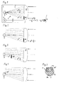
Fig. 1 als Laserdistanzmesser im Fernbereich -
Fig. 2 als Empfangsoptik vonFig. 1 im Nahbereich -
Fig. 3 als Variante des Polarisationsfilters vonFig. 2 -
Fig. 4 als weitere Variante des Polarisationsfilters vonFig. 2 -
Fig. 5 als Photoempfänger vonFig. 4 in Aufsicht -
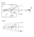
Fig. 6 als Variante der Empfangsoptik im Fernbereich -
Fig. 7 als Empfangsoptik vonFig. 6 im Nahbereich - Nach
Fig. 1 weist ein paraaxialer elektrooptischer Laserdistanzmesser 1 ein handhabbares Gehäuse 2, eine elektrische Strahlquelle 3 in Form einer Laserdiode zur Erzeugung eines modulierten, linear polarisierten, gebündelten und sichtbaren Lichtstrahls 4 und eine dazu parallel versetzt angeordnete Empfangsoptik 5 auf. Längs der Empfangsachse E im Brennpunkt 6 ist ein quer zur Empfangsachse E flächiger Photoempfänger 7 in Form einer Fotodiode zum Empfang von Teilen des von einem Messobjekt 8 in einem Empfangsstrahlenbündel 9 zurückgestreuten Lichtstrahls 4 angeordnet. Dabei ist der Photoempfänger 7 innerhalb des Empfangsstrahlenbündels 9 aber ausserhalb der Empfangsachse E teilweise von einem Polarisationsfilter 10 abgeschattet, der nur die senkrecht zur Polarisation der Strahlquelle 3 polarisierte Komponenten des Lichts durchlässt und somit die reflektierte (gleich polarisierte) Komponente unterdrückt. Der Polarisationsfilter 10 ist in Form eines Schichtensystems direkt auf der Empfangslinse 11 aufgebracht. Der Grossteil des auf den lichtempfindlichen Empfangsflächenbereich des Photoempfängers 7 auftreffenden Empfangsstrahlenbündels 9 des Fernbereichs passiert nicht den Polarisationsfilter 10, so dass alle Polarisationskomponenten den Photoempfänger 7 erreichen. - Nach
Fig. 2 passiert das auf den lichtempfindlichen Empfangsflächenbereich des Photoempfängers 7 auftreffende Empfangsstrahlenbündel 9 des Nahbereichs zum Grossteil den Polarisationsfilter 10, so dass nur die nicht parallel zur Strahlquelle 3 (Fig. 1 ) polarisierten Polarisationskomponenten den Photoempfänger 7 erreichen und somit der (an gut spiegelnden Flächen) reflektierte Anteil wesentlich unterdrückt wird. - Nach
Fig. 3 ist der Polarisationsfilter 10' in Form eines Kristalls zwischen der Empfangslinse 11 und dem Photoempfänger 7 angeordnet. - Nach
Fig. 4 ist der Polarisationsfilter 10" in Form einer Folie direkt auf dem lichtempfindlichen Empfangsflächenbereich des Photoempfängers 7 angeordnet. - Nach
Fig. 5 ist direkt auf dem Photoempfänger 7 eine lichtundurchlässige Blende 12 mit zwei Öffnungen 13a, 13b aufgebracht, die zwei voneinander getrennte, lichtempfindliche Empfangsflächenbereiche erzeugt, wobei ein erster Empfangsbereich auf der Empfangsachse E liegt und der andere zweite Empfangsbereich davon beabstandet ist. Der erste Empfangsbereich wird nur von Licht aus dem Fernbereich und der zweite Empfangsbereich wird nur von Licht aus dem Nahbereich erfasst. Nur auf dem zweiten Empfangsbereich befindet sich der Polarisationsfilter 10 in Form einer Folie. - Nach
Fig. 6 weist ein koaxialer elektrooptischer Laserdistanzmesser 1' ein handhabbares Gehäuse 2, eine elektrische Strahlquelle 3 in Form einer Laserdiode zur Erzeugung eines modulierten, linear polarisierten, gebündelten und sichtbaren Lichtstrahls 4, eine Empfangsoptik 5 mit einem längs der Empfangsachse E im Brennpunkt 6 angeordneten, quer zur Empfangsachse E flächigen Photoempfänger 7 in Form einer Fotodiode zum Empfang von Teilen des von einem Messobjekt 8 in einem Empfangsstrahlenbündel 9 zurückgestreuten Lichtstrahls 4 auf. Dabei ist der Photoempfänger 7 im koaxialen inneren des Empfangsstrahlenbündels 9 teilweise von einem Polarisationsfilter 10"' abgeschattet, der nur die senkrecht zur Polarisation der Strahlquelle 3 polarisierte Komponenten des Lichts durchlässt und somit die reflektierte (gleich polarisierte) Komponente unterdrückt. Der Polarisationsfilter 10"' in Form eines Polarisationsstrahlteilers ist axial zwischen dem Brennpunkt 6 und der Empfangslinse 11 angeordnet und spiegelt den von der quer zur Empfangsachse E orientierten Strahlquelle 3 erzeugten Lichtstrahl 4 koaxial in die Empfangsachse E ein. - Nach
Fig. 7 passiert hingegen das auf den lichtempfindlichen Empfangsflächenbereich des Photoempfängers 7 auftreffende Empfangsstrahlenbündel 9 des Nahbereichs, welches erst hinter dem Brennpunkt 6 fokussiert wird, zum Grossteil den Polarisationsfilter 10"', so dass nur die nicht parallel zur Strahlquelle 3 (Fig. 6 ) polarisierten Polarisationskomponenten den Photoempfänger 7 erreichen und somit der (an gut spiegelnden Flächen) reflektierte Anteil wesentlich unterdrückt wird.
Claims (8)
- Elektrooptischer Laserdistanzmesser mit einem handhabbaren Gehäuse (2), einer elektrischen Strahlquelle (3) zur Erzeugung eines gebündelten Lichtstrahls (4), einer Empfangsoptik (5) mit einem längs der Empfangsachse (E) im Brennpunkt (6) angeordneten, quer zur Empfangsachse (E) flächigen Photoempfänger (7) zum Empfang von Teilen des von einem Messobjekt (8) in einem Empfangsstrahlenbündel (9) zurückgestreuten Lichtstrahls (4), dadurch gekennzeichnet, dass der Photoempfänger (7) innerhalb des Empfangsstrahlenbündels (9) teilweise von einem Polarisationsfilter (10, 10', 10", 10"') abgeschattet ist.
- Laserdistanzmesser nach Anspruch 1, dadurch gekennzeichnet, dass der Polarisationsfilter (10, 10', 10", 10"') parallel zur Polarisation der Strahlquelle (5) undurchlässig ist.
- Laserdistanzmesser nach Anspruch 1 oder 2, dadurch gekennzeichnet, dass der Polarisationsfilter (10, 10', 10") ausserhalb der Empfangsachse (E) angeordnet ist.
- Laserdistanzmesser nach einem der Ansprüche 1 bis 3, dadurch gekennzeichnet, dass der Polarisationsfilter (10, 10', 10") eine direkt an oder in einem Bauteil der Empfangsoptik (5) angeordnete Polarisationsschicht ist.
- Laserdistanzmesser nach einem der Ansprüche 1 bis 4, dadurch gekennzeichnet, dass der Polarisationsfilter (10") direkt auf dem Photoempfänger (7) aufgebracht ist.
- Laserdistanzmesser nach einem der Ansprüche 1 bis 5, dadurch gekennzeichnet, dass der Photoempfänger (7) eine Blende (12) aufweist.
- Laserdistanzmesser nach Anspruch 1 oder 2, dadurch gekennzeichnet, dass der Polarisationsfilter (10"') innerhalb der Empfangsachse (E) zwischen der Empfangslinse (11) und dem Brennpunkt (6) angeordnet ist.
- Laserdistanzmesser nach Anspruch 7, dadurch gekennzeichnet, dass der Polarisationsfilter (10"') ein Polarisationsstrahlteiler ist.
Applications Claiming Priority (1)
| Application Number | Priority Date | Filing Date | Title |
|---|---|---|---|
| DE102007055771A DE102007055771A1 (de) | 2007-12-12 | 2007-12-12 | Laserdistanzmesser |
Publications (2)
| Publication Number | Publication Date |
|---|---|
| EP2071358A2 true EP2071358A2 (de) | 2009-06-17 |
| EP2071358A3 EP2071358A3 (de) | 2012-06-27 |
Family
ID=40547567
Family Applications (1)
| Application Number | Title | Priority Date | Filing Date |
|---|---|---|---|
| EP08105806A Withdrawn EP2071358A3 (de) | 2007-12-12 | 2008-11-17 | Laserdistanzmesser |
Country Status (5)
| Country | Link |
|---|---|
| US (1) | US8068215B2 (de) |
| EP (1) | EP2071358A3 (de) |
| JP (1) | JP5209455B2 (de) |
| CN (1) | CN101458330B (de) |
| DE (1) | DE102007055771A1 (de) |
Cited By (2)
| Publication number | Priority date | Publication date | Assignee | Title |
|---|---|---|---|---|
| EP2597483A1 (de) | 2011-11-25 | 2013-05-29 | Vectronix AG | Entfernungsmesser |
| DE102012006869A1 (de) * | 2012-04-04 | 2013-10-10 | Valeo Schalter Und Sensoren Gmbh | Optoelektronische Sensoreinrichtung, insbesondere Laserscanner, mit einer angepassten Empfangseinheit zur optimierten Empfangspegelreduzierung |
Families Citing this family (9)
| Publication number | Priority date | Publication date | Assignee | Title |
|---|---|---|---|---|
| DE102009029026A1 (de) * | 2009-08-31 | 2011-03-03 | Robert Bosch Gmbh | Vorrichtung zur optischen Distanzmessung sowie Verfahren zur Justierung einer solchen Vorrichtung |
| CN103293529B (zh) * | 2012-06-04 | 2015-04-08 | 南京德朔实业有限公司 | 激光测距装置 |
| CN103991553B (zh) | 2013-02-19 | 2016-02-24 | 成都海存艾匹科技有限公司 | 飞机精准着陆辅助装置 |
| CN103219968B (zh) * | 2013-03-21 | 2016-06-22 | 电子科技大学 | 一种高功率超宽带信号发生装置 |
| PL2963627T3 (pl) * | 2014-07-04 | 2016-11-30 | Urządzenie do osłabiania padającego światła wiązki promieni | |
| WO2017056479A1 (en) * | 2015-09-28 | 2017-04-06 | Ricoh Company, Ltd. | System |
| JP6206560B2 (ja) | 2015-09-28 | 2017-10-04 | 株式会社リコー | システム |
| JP6946921B2 (ja) * | 2017-10-17 | 2021-10-13 | 株式会社デンソー | 発受光装置の筐体 |
| CN112985541A (zh) * | 2019-12-12 | 2021-06-18 | 上海梅山钢铁股份有限公司 | 一种锌锅液位检测装置 |
Citations (3)
| Publication number | Priority date | Publication date | Assignee | Title |
|---|---|---|---|---|
| DE10051302A1 (de) | 2000-10-13 | 2002-04-25 | Jenoptik Jena Gmbh | Laserentfernungsmessgerät für große Messbereiche mit speziellem Empfänger |
| WO2003002939A1 (de) | 2001-06-26 | 2003-01-09 | Robert Bosch Gmbh | Vorrichtung zur optischen distanzmessung über einen grossen messbereich |
| DE10112833C1 (de) | 2001-03-16 | 2003-03-13 | Hilti Ag | Verfahren und Einrichtung zur elektrooptischen Distanzmessung |
Family Cites Families (13)
| Publication number | Priority date | Publication date | Assignee | Title |
|---|---|---|---|---|
| JPS6196625A (ja) * | 1984-10-15 | 1986-05-15 | オムロン株式会社 | 反射形光電スイツチ |
| JPH0511082U (ja) * | 1991-07-24 | 1993-02-12 | 三菱電機株式会社 | レーザ光送受信光学系 |
| US5270795A (en) * | 1992-08-11 | 1993-12-14 | National Research Council Of Canada/Conseil National De Rechereches Du Canada | Validation of optical ranging of a target surface in a cluttered environment |
| US5319434A (en) * | 1992-12-30 | 1994-06-07 | Litton Systems, Inc. | Laser rangefinder apparatus with fiber optic interface |
| US5489984A (en) * | 1994-04-01 | 1996-02-06 | Imra America, Inc. | Differential ranging measurement system and method utilizing ultrashort pulses |
| US5521694A (en) * | 1994-05-10 | 1996-05-28 | Innova Laboratories, Inc. | Laser beam path profile sensor system |
| FR2731522A1 (fr) * | 1995-03-06 | 1996-09-13 | Ruiz Ventura Ricardo | Procede et dispositif de telemetre optique et detecteur d'obstacles |
| US6411370B1 (en) * | 1998-11-23 | 2002-06-25 | Vantageport, Inc. | Optical system and method for measuring distance |
| JP2001174557A (ja) * | 1999-12-16 | 2001-06-29 | Hamamatsu Photonics Kk | 全天候型光学式距離計および距離測定方法 |
| JP3892704B2 (ja) * | 2001-10-30 | 2007-03-14 | ペンタックス株式会社 | 光波測距儀 |
| DE10160439A1 (de) * | 2001-12-08 | 2003-06-26 | Bosch Gmbh Robert | Laserentfernungsmeßgerät |
| WO2003089950A2 (en) * | 2002-04-15 | 2003-10-30 | Toolz, Ltd. | Distance measurement device |
| DE102005045280B3 (de) * | 2005-09-22 | 2006-12-28 | Leuze Electronic Gmbh & Co Kg | Distanzsensor |
-
2007
- 2007-12-12 DE DE102007055771A patent/DE102007055771A1/de not_active Ceased
-
2008
- 2008-11-17 EP EP08105806A patent/EP2071358A3/de not_active Withdrawn
- 2008-12-10 JP JP2008314194A patent/JP5209455B2/ja active Active
- 2008-12-10 US US12/316,301 patent/US8068215B2/en active Active
- 2008-12-11 CN CN200810184629.0A patent/CN101458330B/zh active Active
Patent Citations (3)
| Publication number | Priority date | Publication date | Assignee | Title |
|---|---|---|---|---|
| DE10051302A1 (de) | 2000-10-13 | 2002-04-25 | Jenoptik Jena Gmbh | Laserentfernungsmessgerät für große Messbereiche mit speziellem Empfänger |
| DE10112833C1 (de) | 2001-03-16 | 2003-03-13 | Hilti Ag | Verfahren und Einrichtung zur elektrooptischen Distanzmessung |
| WO2003002939A1 (de) | 2001-06-26 | 2003-01-09 | Robert Bosch Gmbh | Vorrichtung zur optischen distanzmessung über einen grossen messbereich |
Cited By (4)
| Publication number | Priority date | Publication date | Assignee | Title |
|---|---|---|---|---|
| EP2597483A1 (de) | 2011-11-25 | 2013-05-29 | Vectronix AG | Entfernungsmesser |
| US9036135B2 (en) | 2011-11-25 | 2015-05-19 | Vectronix Ag | Distance measuring device |
| DE102012006869A1 (de) * | 2012-04-04 | 2013-10-10 | Valeo Schalter Und Sensoren Gmbh | Optoelektronische Sensoreinrichtung, insbesondere Laserscanner, mit einer angepassten Empfangseinheit zur optimierten Empfangspegelreduzierung |
| US9606222B2 (en) | 2012-04-04 | 2017-03-28 | Valeo Schalter Und Sensoren Gmbh | Optoelectronic sensor device, in particular laser scanner, having an adapted receiving unit for optimized reduction of the reception level |
Also Published As
| Publication number | Publication date |
|---|---|
| DE102007055771A1 (de) | 2009-06-18 |
| JP2009145340A (ja) | 2009-07-02 |
| CN101458330B (zh) | 2014-04-30 |
| US8068215B2 (en) | 2011-11-29 |
| JP5209455B2 (ja) | 2013-06-12 |
| US20090153834A1 (en) | 2009-06-18 |
| CN101458330A (zh) | 2009-06-17 |
| EP2071358A3 (de) | 2012-06-27 |
Similar Documents
| Publication | Publication Date | Title |
|---|---|---|
| EP2071358A2 (de) | Laserdistanzmesser | |
| CN101405613B (zh) | 用于光学测距的装置 | |
| EP1405037B1 (de) | Vorrichtung zur optischen distanzmessung über einen grossen messbereich | |
| EP3239734B1 (de) | Dynamikerweiterung einer distanzmessvorrichtung mit einem variablen optischen abschwächelement im sendekanal | |
| CN110914706B (zh) | Lidar测量装置 | |
| DE102004037137B4 (de) | Verfahren und Vorrichtung zur Entfernungsmessung | |
| DE10339495B4 (de) | Anordnung zur optischen Detektion eines bewegten Targetstromes für eine gepulste energiestrahlgepumpte Strahlungserzeugung | |
| DE102004042466A1 (de) | Vorrichtung und Verfahren zur optischen Distanzmessung | |
| DE112017006183T5 (de) | Laserradarvorrichtung | |
| DE102017200691B4 (de) | Projektionsvorrichtung und Verfahren zum Abtasten eines Raumwinkelbereichs mit einem Laserstrahl | |
| CN205300800U (zh) | 荧光光纤温度传感解调系统 | |
| DE102004033928A1 (de) | Abtastvorrichtung zum Vermessen der Konturen eines Objektes | |
| WO2003087875A1 (de) | Vorrichtung zum erzeugen eines dreidimensionalen umgebungsbildes | |
| DE10147987B9 (de) | Optoelektronisches Bauelement | |
| DE3485931T2 (de) | Einrichtung zur entfernungsmessung. | |
| DE102015004903A1 (de) | Optoelektronische Messvorrichtung | |
| WO2018086786A1 (de) | Partikelsensor mit wenigstens zwei laser-doppler-sensoren | |
| US7826039B2 (en) | Target acquisition device | |
| JP6278457B2 (ja) | 非破壊検査方法およびその装置 | |
| WO2015003833A1 (de) | Bestimmung eines abstands und eines winkels in bezug auf eine ebene mittels mehrerer entfernungsmessungen | |
| DE102022004473A1 (de) | Sensoranordnung zum Erfassen mindestens einer ersten Torsion eines Rotorblatts einer Windkraftanlage | |
| CN212275978U (zh) | 实时测量机载高光谱成像激光雷达光谱的装置 | |
| DE102008020201A1 (de) | Messvorrichtung | |
| DE102005045280B3 (de) | Distanzsensor | |
| DE19805200B4 (de) | Auswerteverfahren für eine Dickenmessung an Objekten |
Legal Events
| Date | Code | Title | Description |
|---|---|---|---|
| PUAI | Public reference made under article 153(3) epc to a published international application that has entered the european phase |
Free format text: ORIGINAL CODE: 0009012 |
|
| AK | Designated contracting states |
Kind code of ref document: A2 Designated state(s): AT BE BG CH CY CZ DE DK EE ES FI FR GB GR HR HU IE IS IT LI LT LU LV MC MT NL NO PL PT RO SE SI SK TR |
|
| AX | Request for extension of the european patent |
Extension state: AL BA MK RS |
|
| PUAL | Search report despatched |
Free format text: ORIGINAL CODE: 0009013 |
|
| AK | Designated contracting states |
Kind code of ref document: A3 Designated state(s): AT BE BG CH CY CZ DE DK EE ES FI FR GB GR HR HU IE IS IT LI LT LU LV MC MT NL NO PL PT RO SE SI SK TR |
|
| AX | Request for extension of the european patent |
Extension state: AL BA MK RS |
|
| RIC1 | Information provided on ipc code assigned before grant |
Ipc: G01S 17/08 20060101AFI20120524BHEP Ipc: G01S 17/32 20060101ALI20120524BHEP Ipc: G01S 17/10 20060101ALI20120524BHEP Ipc: G01S 7/499 20060101ALI20120524BHEP |
|
| 17P | Request for examination filed |
Effective date: 20130102 |
|
| AKX | Designation fees paid |
Designated state(s): CH DE FR GB IT LI |
|
| STAA | Information on the status of an ep patent application or granted ep patent |
Free format text: STATUS: THE APPLICATION IS DEEMED TO BE WITHDRAWN |
|
| 18D | Application deemed to be withdrawn |
Effective date: 20130103 |