EP2071423B1 - Augmentation de contrôle à trajet vertical utilisant des surfaces de contrôle latéral - Google Patents
Augmentation de contrôle à trajet vertical utilisant des surfaces de contrôle latéral Download PDFInfo
- Publication number
- EP2071423B1 EP2071423B1 EP08253760.6A EP08253760A EP2071423B1 EP 2071423 B1 EP2071423 B1 EP 2071423B1 EP 08253760 A EP08253760 A EP 08253760A EP 2071423 B1 EP2071423 B1 EP 2071423B1
- Authority
- EP
- European Patent Office
- Prior art keywords
- aircraft
- control
- vertical
- error
- vertical path
- Prior art date
- Legal status (The legal status is an assumption and is not a legal conclusion. Google has not performed a legal analysis and makes no representation as to the accuracy of the status listed.)
- Active
Links
Images

Classifications
-
- G—PHYSICS
- G05—CONTROLLING; REGULATING
- G05D—SYSTEMS FOR CONTROLLING OR REGULATING NON-ELECTRIC VARIABLES
- G05D1/00—Control of position, course, altitude or attitude of land, water, air or space vehicles, e.g. using automatic pilots
- G05D1/04—Control of altitude or depth
- G05D1/06—Rate of change of altitude or depth
- G05D1/0607—Rate of change of altitude or depth specially adapted for aircraft
- G05D1/0653—Rate of change of altitude or depth specially adapted for aircraft during a phase of take-off or landing
- G05D1/0676—Rate of change of altitude or depth specially adapted for aircraft during a phase of take-off or landing specially adapted for landing
Definitions
- the disclosure relates to aircraft flight control systems and specifically to the automatic control of an aircraft's flight path.
- Automatic pilot systems are widely used in the aviation industry to control the flight path of an aircraft.
- Conventional control systems typically utilize the elevator as the control surface for effecting changes in the aircraft's vertical path.
- One objective of the disclosure is to enhance the precision of vertical path control afforded by one or more conventional pitch control systems coupled with an automatic pilot system, both during landing and non-landing flight situations.
- an automatic landing is a vertical path tracking task that requires precise vertical path control in order to achieve acceptable performance.
- Automatic landing capability is required for operations in the most severe low visibility weather, referred to as Category IIIB low weather minima, and is used in less restrictive weather minimums to enhance safety and reduce flight crew work load.
- An Automatic Landing System (ALS) provides the precise vertical and lateral path guidance necessary to meet the stringent performance requirements specified for low weather minimum operations.
- the vertical path guidance provided by an ALS includes both glide path control and the flare maneuver. Precise control of vertical position relative to the desired vertical path is essential in order to achieve the performance required for Category III operations.
- the glide path provides the established descent gradient and longitudinal position reference for final approach flight path guidance.
- the flare maneuver provides the transition from the glide path to touchdown at the desired location on the runway.
- the ALS will land the aircraft at the same point on the runway regardless of environment or facility. In other words, the design must be very robust given the wide range of environmental conditions, terrain, and runway characteristics that the aircraft will be subjected to during automatic landings.
- the vertical path tracking provided by the ALS is significantly affected by shearing winds, terrain, and runway characteristics. Any enhancement of an existing autopilot design that improves vertical path tracking will reduce the impact of the aforementioned disturbances during automatic landing operations.
- the autopilot used in airplanes such as the 777, 757, 767, and 747-400 utilizes a vertical position control law design to generate an elevator command that provides glide path control and the flare maneuver.
- the elevator command is generated with an elevator vertical position feedback control system.
- the vertical position control law design produces a pitch attitude command that is proportional to the altitude error and altitude rate error and the integral of the altitude error.
- the error is defined as the difference between the command and the actual (as measured by a sensor).
- the pitch attitude command is converted into an elevator command that is used to move the elevator control surface.
- the design is tuned to provide accurate vertical path tracking with acceptable stability characteristics.
- Autopilots typically utilize a predictive or feed forward elevator compensation of some sort in combination with elevator feedback control to achieve disturbance rejection.
- This combination of feed forward elevator compensation and elevator feedback control allow performance objectives to be met without resorting to excessively high and potentially destabilizing feedback gains.
- the types of elevator feed forward compensation utilized are typically either short term moment compensation or long term force compensation.
- a control surface command (elevator) is generated such that a moment is created that cancels the moment predicted to be generated by the disturbance.
- a pitch attitude command is generated to counteract the steady state trim changes due to a disturbance.
- Short term moment compensation tends to limit pitch attitude change in response to a disturbance
- long term force compensation tends to generate pitch attitude change in response to a disturbance.
- Short term moment compensation is used for balancing pitching moments due to changes in stabilizer, and changes in thrust and ground effects, but is not very effective for dealing with vertical path disturbance due to changing winds.
- Long term force compensation is quite effective in countering the disturbances due to changing winds.
- the pitch attitude changes resulting from long term force compensation tend to result in undesirable pitch activity from a fight crew acceptability standpoint.
- the pitch attitude of the airplane must be limited to prevent ground contact of the nose landing gear prior to the main landing gear and ground contact of the aft body (tail strike). While limiting the pitch attitude within the geometrical constraints reduces the probability of a nose gear first contact and tail strike during an automatic landing, the ability of the autopilot to maintain the commanded vertical path using a vertical position elevator feedback control system and feed forward elevator compensation can be diminished by these geometrical constraints. For example, during a flare maneuver, the geometrical constraints may prevent the autopilot from maneuvering as aggressively in response to the vertical path upset caused by shearing winds.
- a method for reducing vertical position control errors of an aircraft is needed to decrease one or more problems associated with one or more of the existing methods.
- EP 0,530,924 discloses an aircraft flare control system in which a signal commanding pitch or roll correction is output when the aircraft deviates from the flare envelope.
- a method for reducing vertical position control errors of an aircraft.
- displacement of the aircraft from a commanded vertical path may be determined.
- it may be determined whether a magnitude of a vertical path error is outside a pre-determined criteria.
- no more steps of the method may be followed if the vertical path error is not outside the criteria, and the vertical path error may be converted into a delta lift command if the vertical path error is outside the criteria.
- the delta lift command may be limited and/or filtered.
- the limited and/or filtered delta lift command may be converted into lateral surface position commands.
- the lateral surface position commands may be communicated to lateral control surface actuators to move the control surfaces according to the lateral surface position commands such that the vertical position error may be reduced.
- a method for reducing vertical position errors of an aircraft.
- an aircraft's actual position may be compared to a commanded position of the aircraft.
- an autopilot system may be used to determine altitude error and altitude rate error values.
- the altitude error and altitude rate error values may be passed through a set of criteria to determine if action should be taken. No more steps of the method may be followed if the altitude error and altitude rate error values do not meet the criteria for action. If the altitude error and altitude rate error values do meet the criteria, in yet another step, the altitude error and altitude rate error values may be multiplied by at least one gain signal to produce two delta lift commands.
- the two delta lift commands may be summed to produce a single delta lift command.
- the single delta lift command may be used in unison with a conventional vertical position feedback elevator control loop to maintain the commanded position of the aircraft.
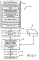
- FIG. 1 shows a system block diagram 10 which may be used under one embodiment of the disclosure.
- the system 10 may include sensors 12, an autopilot system 14, a flight control system 16, one or more actuators 18, one or more control surfaces 20, and one or more computers 22.
- the sensors 12 may comprise one or more of a vertical path sensor, a glidepath sensor, an instrument landing system sensor, a global positioning system sensor, a microwave landing positioning system landing system sensor, a radio altitude sensor, a pressure altitude sensor, an inertial sensor, and/or one or more other types of sensors.
- the autopilot system 14 may comprise a vertical path deviation calculator, and/or other types of autopilot devices.
- the flight control system 16 may comprise one or more of a delta lift to surface deflection converter, a surface command processor, and/or other types of flight control functions.
- the one or more actuators 18 may comprise one or more devices that may be used to move the control surfaces 20.
- the one or more computers 22 may comprise a vertical position feedback symmetric lateral control surface deflection (or direct lift) computer.
- the one or more computers 22 may further comprise one or more of a processor, a memory, an autopilot interface module, a flight control interface module, and/or other types of computer systems. In other embodiments, the one or more computers 22 may comprise a separate processing computer, may be embedded in the autopilot system 14, and/or may be embedded in the flight control system 16.
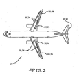
- control surfaces 20 may comprise spoilers 24, ailerons 26, flaperons 28, an elevator 30, and/or other types of control surfaces.
- the spoilers 24 may be deflected asymmetrically for lateral control, and/or can be symmetrically deflected for longitudinal control, and/or lift generation/reduction .
- the ailerons 26 may be deflected asymmetrically for lateral control, and/or may be symmetrically deflected for longitudinal control and/or lift generation.
- the flaperons 28 may be deflected asymmetrically for lateral control, and/or may be symmetrically deflected for longitudinal control and/or lift generation.
- the elevator 30 may comprise a longitudinal control surface.
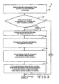
- Figure 3 shows a flowchart of one embodiment of a method 32 for reducing vertical position errors in an aircraft 23.
- Figure 4 shows one embodiment of a block diagram 34 which may be followed to implement the method 32 of Figure 3 .
- the aircraft's displacement from its commanded vertical path may be determined. This may be done utilizing the aircraft's autopilot's conventional elevator feedback vertical position control law using the computer 22.
- This vertical displacement may comprise the aircraft's vertical path error signal which may be determined by the autopilot system 14 utilizing the aircraft's sensors 12 and signal synthesis to determine the aircraft's actual vertical position relative to the aircraft's commanded vertical position.
- the aircraft's glideslope signal, radio altimeter signal, and/or other types of signals, devices, and/or mechanisms may be used to assist in determining the aircraft's displacement from the commanded vertical path.
- the vertical displacement of the aircraft 23 may be caused by a disturbance, such as a wind gust, glideslope beam bend, and/or due to abrupt changes in radio altitude caused by changing terrain.
- Step 36 may further comprise, as shown in Figure 4 , determining both the altitude error signal 38 and the altitude rate error signal 40 using the automatic pilot system's 14 vertical position control law and/or computer 22.
- These altitude and altitude rate error signals 38 and 40 respectively may indicate the difference in the commanded vertical position and vertical rate from the actual vertical position and vertical rate of the aircraft 23.
- a determination may be made using the computer 22 as to whether the magnitude of the vertical path error is outside (exceeds) a set of criteria such as a threshold or one of a set of predetermined criteria (represented as a deadzone/deadzone filter/and/or filter) and therefore warrants a deflection of the lateral control surfaces 20.
- a set of criteria such as a threshold or one of a set of predetermined criteria (represented as a deadzone/deadzone filter/and/or filter) and therefore warrants a deflection of the lateral control surfaces 20.
- Factors such as actuator wear, surface fatigue, and system stability may be considered in setting the criteria.
- Step 42 may comprise sending/passing the altitude error signal 38 through a set of criteria (e.g., deadzone/deadzone filter/and/or filter) 44 and the altitude rate error signal 40 through a set of criteria (similarly represented, e.g., as a deadzone/deadzone filter/and/or filter) 46 using the autopilot system 14 and/or computer 22.
- a set of criteria e.g., deadzone/deadzone filter/and/or filter
- the method may conclude/end 63 without doing/completing any more steps of the method. If the vertical path error exceeds the criteria, then in step 47 the vertical path error may be converted into a delta lift command using the computer 22 shown in Figure 1 .
- the delta lift command may be proportional to the vertical position error.
- Step 47 may comprise, as shown in Figure 4 , using the autopilot system 14 and/or computer 22 to multiply the altitude error signal 38 by a first gain signal 48 to produce a first delta lift command 50, to multiply the altitude rate error signal 40 by a second gain signal 52 to produce a second delta lift command 53, and to sum the first delta lift command 50 and the second delta lift command 53 to obtain the single (or total) delta lift command 54.
- the gains K may be determined using methods well-known to those skilled in the art.
- the first and second gain signals 48 and 52 may be identical. In other embodiments, the first and second gain signals 48 and 52 may vary.
- step 56 the delta lift command 54 may be limited and/or filtered. This may occur by communicating (passing) on the delta lift command 54 to the flight control system 16 and limiting and/or filtering the delta lift command 54 using the computer 22.
- the limiting and/or filtering could be done in computer 22 or in the flight control system 16 based on the delta lift available from the lateral control surface deflections to prevent command saturation. In other embodiments, the limiting and/or filtering may be done by the autopilot system 14.
- Step 56 may comprise, as shown in Figure 4 , limiting and/or filtering 57 the delta lift command 54 using the flight control system 16 and/or computer 22. This limiting and/or filtering may prevent commanding more delta lift than is available with the applicable lateral control surfaces 20 shown in Figure 2 . If any of the input signals are exceptionally noisy, then appropriate filtering of the delta lift command 54 may be applied. Other sorts of limiting and/or filtering may also be applied as appropriate.
- step 58 the delta lift command 54, which may have been limited and/or filtering in step 56, may then be converted using the computer 22 into lateral surface position commands for the control surfaces 20 by the flight control system 16, such as the spoiler 24, the flaperon 28, and/or other control surfaces 20.
- the limited and/or filtered delta lift command 54 may be converted into lateral surface position commands for the control surfaces 20 by the autopilot system 14.
- the lateral surface position commands may comprise symmetric lateral control surface commands for the control surfaces 20.
- Step 58 may comprise, as shown in Figure 4 , converting the delta lift command 54 (which may have been limited) into lateral surface position commands 60 using the flight control system 16 and/or computer 22.
- the lateral surface position commands may be communicated using the computer 22 to the lateral control surface actuators 18 which may control/move the control surfaces 20 according to the lateral surface position commands using the flight control system 16.
- the autopilot system 14 may communicate the lateral surface position commands to the lateral control surface actuators 18 to control/move the control surfaces 20 according to the lateral surface position commands.
- the feedback control loop may work in parallel/unison with the conventional vertical position feedback elevator control loop (the elevator command) to maintain the commanded vertical path of the aircraft 23 and to correspondingly reduce vertical position error.
- Step 62 may comprise communicating 64 the lateral surface position commands to the lateral control surface actuators 18 to control/move the control surfaces 20 using the flight control system 16.
- the embodiments of the disclosure may be used to enhance the accuracy of the automatic pilot vertical position command tracking task provided by one or more of the conventional longitudinal control systems.
- the enhancement may be achieved by using a vertical position feedback control to produce commands that result in symmetric deflections of lateral control surfaces on the aircraft's wings for the purpose of augmenting the autopilot's existing vertical position control. Symmetric deflections of the wing's lateral control surfaces may result in small changes in lift.
- the commands may be proportional to the vertical path error signal used to drive a conventional longitudinal control system. In such manner, vertical position command tracking may be improved during an automatic landing.
- the embodiments of the disclosure could be applied to any phase of flight where a vertical position control strategy is utilized.
- the improved vertical position command tracking achieved by one or more embodiments of the disclosure may increase the robustness and improve the performance of an existing automatic landing system. Symmetric deflections of the lateral control surfaces may produce significantly less pitching movement than elevator deflections. Therefore, one or more embodiments of the disclosure may provide a unique way to improve vertical position command tracking during an automatic landing without creating pitch activity that may be objectionable to the flight crew or requiring excessively high vertical position feedback gains that may compromise system stability.
- the development and certification of an automatic landing system may be a costly endeavor, requiring extensive flight testing, gain tuning, and simulation model updates.
- a more robust automatic landing system may be less sensitive to discrepancies between the simulation models for aerodynamic and sensors and the actual aircraft aerodynamics and sensor characteristics, and may therefore reduce the overall cost and design refinement involved in certification of the automatic landing system. Additionally, lower vertical position feedback gains may reduce the possibility of structural mode interaction.
Landscapes
- Engineering & Computer Science (AREA)
- Aviation & Aerospace Engineering (AREA)
- Radar, Positioning & Navigation (AREA)
- Remote Sensing (AREA)
- Physics & Mathematics (AREA)
- General Physics & Mathematics (AREA)
- Automation & Control Theory (AREA)
- Control Of Position, Course, Altitude, Or Attitude Of Moving Bodies (AREA)
- Feedback Control In General (AREA)
Claims (15)
- Procédé pour réduire des erreurs de position verticale d'un aéronef (23) comprenant les étapes de :déterminer (36) le déplacement d'un aéronef à partir d'un chemin vertical commandé de l'aéronef ;déterminer (42) si une grandeur d'une erreur de chemin vertical est en dehors d'un critère (44, 46) ;ne pas suivre d'autres étapes du procédé si l'erreur de chemin vertical n'est pas en dehors du critère et convertir (47) l'erreur de chemin vertical en une commande de levée delta (50, 53, 54) si l'erreur de chemin vertical est en dehors du critère ;au moins un d'une limitation et d'un filtrage (57) de la commande de levée delta (54) ;convertir (58) la commande de levée delta en des commandes de position de la surface latérale (60) pour des surfaces de commande (20) ; etcommuniquer (62) les commandes de position de surface latérale en actionneurs de surface de commande latérale (18) pour déplacer les surfaces de commande en accord avec les commandes de position de surface latérale,caractérisé en établissant les critères en utilisant au moins une parmi une usure de l'actionneur, une fatigue de surface et une stabilité du système.
- Procédé selon la revendication 1, dans lequel l'étape de détermination du déplacement de l'aéronef du chemin vertical commandé de l'aéronef utilise une loi de commande de position verticale de rétroaction de gouverne de profondeur classique par pilote automatique (22).
- Procédé selon la revendication 1, dans lequel l'étape de détermination du déplacement de l'aéronef du chemin vertical commandé de l'aéronef comprend la détermination d'un signal d'erreur de chemin vertical de l'aéronef en utilisant un système à pilote automatique (14) de l'aéronef.
- Procédé selon l'une quelconque des revendications précédentes, dans lequel l'étape de détermination du déplacement de l'aéronef du chemin vertical commandé de l'aéronef utilise des capteurs (12) et une synthèse des signaux pour déterminer la position verticale actuelle de l'aéronef relativement à la position verticale commandée de l'aéronef.
- Procédé selon l'une quelconque des revendications précédentes, dans lequel l'étape de détermination du déplacement de l'aéronef utilise au moins un parmi un signal d'alignement de descente, un signal d'altimètre radio et un signal.
- Procédé selon la revendication 1, dans lequel l'étape de détermination du déplacement de l'aéronef utilise une loi de commande de position vertical à système de pilote automatique pour déterminer un signal d'erreur d'altitude (38) comprenant une différence dans une position verticale commandée d'une position verticale actuelle de l'aéronef et pour déterminer un signal d'erreur de taux d'altitude (40) comprenant une différence dans un taux vertical commandé d'un taux vertical actuel de l'aéronef.
- Procédé selon l'une quelconque des revendications précédentes, dans lequel l'étape de détermination si la grandeur de l'erreur du chemin vertical est en dehors des critères (44, 46) comprend l'envoi d'un signal d'erreur d'altitude (38) et d'une erreur de taux d'altitude (40) à travers au moins un des critères et une zone morte utilisant un système à pilote automatique (14).
- Procédé selon l'une quelconque des revendications précédentes, dans lequel l'étape de limitation de la commande de levée delta utilise au moins un parmi un système à pilote automatique (14) et un système de commande de vol (16).
- Procédé selon l'une quelconque des revendications précédentes, dans lequel la commande de levée delta est proportionnelle à une erreur de position verticale.
- Procédé selon l'une quelconque des revendications précédentes, dans lequel l'étape de conversion de l'erreur du chemin vertical en commande de levée delta utilise un système à pilote automatique pour multiplier un signal d'erreur d'altitude (38) par un premier signal de gain (48) pour produire une première commande de levée delta (50), pour multiplier un signal d'erreur de taux d'altitude (40) par un deuxième signal de gain (52) pour produire une deuxième commande de levée delta (53), et pour additionner la première commande de levée delta et la deuxième commande de levée delta pour obtenir une commande de levée delta totale (54).
- Procédé selon l'une quelconque des revendications précédentes, dans lequel l'étape d'au moins un parmi la limitation et le filtrage (57) de la commande de levée delta est effectué en utilisant un ordinateur (22) basé sur une levée delta disponible de déflexions de la surface de commande latérale pour prévenir une saturation de commande.
- Procédé selon l'une quelconque des revendications précédentes, comprenant en outre l'étape consistant à filtrer la commande de levée delta s'il y a des signaux d'entrée qui sont bruyants.
- Procédé selon l'une quelconque des revendications précédentes, dans lequel les surfaces de commande (20) comprennent au moins une parmi un déflecteur (24), un flapéron (28), un aileron (26) et un élévateur (30).
- Procédé selon l'une quelconque des revendications précédentes, dans lequel les commandes de position de la surface latérale (60) comprennent des commandes de surface de commande latérale symétriques pour les surfaces de commande (20).
- Procédé selon l'une quelconque des revendications précédentes, dans lequel une boucle de commande de rétroaction fonctionne conjointement avec une boucle de gouverne de profondeur à rétroaction de position verticale classique pour maintenir le chemin vertical commandé de l'aéronef et pour réduire l'erreur de position verticale.
Priority Applications (1)
| Application Number | Priority Date | Filing Date | Title |
|---|---|---|---|
| EP15175420.7A EP3037908A3 (fr) | 2007-11-27 | 2008-11-19 | Augmentation de contrôle d'un trajet vertical utilisant des surfaces de contrôle latéral |
Applications Claiming Priority (1)
| Application Number | Priority Date | Filing Date | Title |
|---|---|---|---|
| US11/945,803 US9671788B2 (en) | 2007-11-27 | 2007-11-27 | Vertical path control augmentation using lateral control surfaces |
Related Child Applications (1)
| Application Number | Title | Priority Date | Filing Date |
|---|---|---|---|
| EP15175420.7A Division EP3037908A3 (fr) | 2007-11-27 | 2008-11-19 | Augmentation de contrôle d'un trajet vertical utilisant des surfaces de contrôle latéral |
Publications (3)
| Publication Number | Publication Date |
|---|---|
| EP2071423A2 EP2071423A2 (fr) | 2009-06-17 |
| EP2071423A3 EP2071423A3 (fr) | 2014-04-23 |
| EP2071423B1 true EP2071423B1 (fr) | 2015-07-08 |
Family
ID=40490999
Family Applications (2)
| Application Number | Title | Priority Date | Filing Date |
|---|---|---|---|
| EP08253760.6A Active EP2071423B1 (fr) | 2007-11-27 | 2008-11-19 | Augmentation de contrôle à trajet vertical utilisant des surfaces de contrôle latéral |
| EP15175420.7A Withdrawn EP3037908A3 (fr) | 2007-11-27 | 2008-11-19 | Augmentation de contrôle d'un trajet vertical utilisant des surfaces de contrôle latéral |
Family Applications After (1)
| Application Number | Title | Priority Date | Filing Date |
|---|---|---|---|
| EP15175420.7A Withdrawn EP3037908A3 (fr) | 2007-11-27 | 2008-11-19 | Augmentation de contrôle d'un trajet vertical utilisant des surfaces de contrôle latéral |
Country Status (2)
| Country | Link |
|---|---|
| US (1) | US9671788B2 (fr) |
| EP (2) | EP2071423B1 (fr) |
Families Citing this family (19)
| Publication number | Priority date | Publication date | Assignee | Title |
|---|---|---|---|---|
| AU2009327362A1 (en) * | 2008-12-19 | 2011-08-04 | Xollai, Llc | System and method for determining an orientation and position of an object |
| US8374736B1 (en) | 2009-12-02 | 2013-02-12 | The Boeing Company | Runway slope compensation for an automatic landing system |
| US8712606B2 (en) * | 2012-04-27 | 2014-04-29 | The Boeing Company | System and method for configuring a direct lift control system of a vehicle |
| US9051061B2 (en) * | 2012-12-14 | 2015-06-09 | Safe Flight Instrument Corporation | Systems and methods for safely landing an aircraft |
| US12260769B1 (en) | 2012-12-28 | 2025-03-25 | Otto Aero Company | System and apparatus for reducing the urgency of a flight condition |
| US11657721B1 (en) | 2013-08-26 | 2023-05-23 | Otto Aero Company | Aircraft with flight assistant |
| US20140343765A1 (en) | 2012-12-28 | 2014-11-20 | Sean Patrick Suiter | Flight Assistant with Automatic Configuration and Landing Site Selection |
| US9430938B2 (en) | 2013-03-04 | 2016-08-30 | Hello Inc. | Monitoring device with selectable wireless communication |
| US10058290B1 (en) | 2013-06-21 | 2018-08-28 | Fitbit, Inc. | Monitoring device with voice interaction |
| US10004451B1 (en) | 2013-06-21 | 2018-06-26 | Fitbit, Inc. | User monitoring system |
| US9993166B1 (en) | 2013-06-21 | 2018-06-12 | Fitbit, Inc. | Monitoring device using radar and measuring motion with a non-contact device |
| US9828113B2 (en) | 2013-11-05 | 2017-11-28 | Safe Flight Instrument Corporation | Tailstrike warning system |
| US9546003B2 (en) | 2014-03-14 | 2017-01-17 | Safe Flight Instrument Corporation | Deflare pitch command |
| US9346552B2 (en) | 2014-04-11 | 2016-05-24 | Safe Flight Instrument Corporation | Autothrottle retard control |
| US10227742B2 (en) | 2015-06-05 | 2019-03-12 | Neusch Innovations, Lp | Anti-ram sliding crash gate |
| US20170008639A1 (en) | 2015-07-08 | 2017-01-12 | Safe Flight Instrument Corporation | Aircraft turbulence detection |
| US9989972B2 (en) * | 2016-02-22 | 2018-06-05 | The Boeing Company | Systems and methods to prevent an aircraft from tail contact with the ground |
| US12384550B2 (en) | 2021-12-23 | 2025-08-12 | Electra Aero, Inc. | System and method for controlling flight path of a blown lift aircraft |
| WO2023122111A1 (fr) | 2021-12-23 | 2023-06-29 | Electra Aero, Inc. | Système et procédé de commande de trajectoire de vol d'un aéronef à portance soufflée |
Family Cites Families (21)
| Publication number | Priority date | Publication date | Assignee | Title |
|---|---|---|---|---|
| US3343221A (en) * | 1964-08-07 | 1967-09-26 | United Shoe Machinery Corp | Extensible conduit for an injection molding machine |
| US3333795A (en) | 1966-01-10 | 1967-08-01 | Collins Radio Co | Flare computer |
| US3626163A (en) | 1970-01-28 | 1971-12-07 | Us Army | Automatic landing system |
| US3658280A (en) * | 1970-10-29 | 1972-04-25 | Mc Donnell Douglas Corp | Altitude and glide slope track controller |
| US3738594A (en) | 1971-08-16 | 1973-06-12 | Mc Donnell Douglas Corp | Lift control mechanism |
| US4261537A (en) * | 1979-02-28 | 1981-04-14 | The United States Of America As Represented By The Administrator Of The National Aeronautics And Space Administration | Velocity vector control system augmented with direct lift control |
| US4377848A (en) * | 1980-10-16 | 1983-03-22 | Sperry Corporation | Altitude capture mode for aircraft automatic flight control system |
| US4617633A (en) | 1984-05-29 | 1986-10-14 | The United States Of America As Represented By The Secretary Of The Air Force | Direct lift command blending |
| US4956780A (en) * | 1988-12-08 | 1990-09-11 | The Boeing Company | Flight path angle command flight control system for landing flare |
| US5377937A (en) * | 1991-09-03 | 1995-01-03 | The Boeing Company | Aircraft flare control system utilizing an envelope limiter |
| IL115977A (en) * | 1995-11-14 | 1998-10-30 | Israel Aircraft Ind Ltd | System and method for automatically landing an aircraft |
| US5823479A (en) | 1996-05-20 | 1998-10-20 | The Boeing Company | Landing attitude modifier for airplane |
| US5908176A (en) * | 1997-01-14 | 1999-06-01 | The United States Of America As Represented By The Administrator Of The National Aeronautics And Space Administration | In-flight adaptive performance optimization (APO) control using redundant control effectors of an aircraft |
| DE19819341C2 (de) * | 1998-04-30 | 2000-06-15 | Daimler Chrysler Aerospace | Verfahren zur Reduktion von an einem Flugzeug auftretenden Böenlasten unterhalb der Reiseflughöhe |
| US6575410B2 (en) * | 2001-04-25 | 2003-06-10 | Safe Flight Instrument Corporation | Glide slope tracking system |
| US6641086B2 (en) * | 2001-08-14 | 2003-11-04 | Northrop Grumman Corporation | System and method for controlling an aircraft |
| US6870490B2 (en) * | 2001-08-23 | 2005-03-22 | Honeywell International Inc. | Display of altitude and path capture trajectories |
| GB0127254D0 (en) * | 2001-11-13 | 2002-01-02 | Lucas Industries Ltd | Aircraft flight surface control system |
| FR2857760B1 (fr) * | 2003-07-15 | 2005-09-23 | Airbus France | Systeme pour commander automatiquement des dispositifs hypersustentateurs d'un aeronef, en particulier des becs de bord d'attaque d'aile. |
| EP1768899B1 (fr) * | 2004-07-16 | 2013-12-11 | Airbus Operations | Procede et dispositif d'amelioration de la manoeuvrabilite d'un aeronef lors des phases d'approche avant l'atterrissage puis d'arrondi |
| US7551989B2 (en) * | 2006-06-21 | 2009-06-23 | Calspan Corporation | Autonomous outer loop control of man-rated fly-by-wire aircraft |
-
2007
- 2007-11-27 US US11/945,803 patent/US9671788B2/en active Active
-
2008
- 2008-11-19 EP EP08253760.6A patent/EP2071423B1/fr active Active
- 2008-11-19 EP EP15175420.7A patent/EP3037908A3/fr not_active Withdrawn
Also Published As
| Publication number | Publication date |
|---|---|
| EP2071423A2 (fr) | 2009-06-17 |
| EP3037908A3 (fr) | 2016-07-20 |
| US20090138144A1 (en) | 2009-05-28 |
| US9671788B2 (en) | 2017-06-06 |
| EP3037908A2 (fr) | 2016-06-29 |
| EP2071423A3 (fr) | 2014-04-23 |
Similar Documents
| Publication | Publication Date | Title |
|---|---|---|
| EP2071423B1 (fr) | Augmentation de contrôle à trajet vertical utilisant des surfaces de contrôle latéral | |
| US8275496B2 (en) | Longitudinal and vertical gust feed forward compensation using lateral control surfaces | |
| US8165733B2 (en) | Stall, buffeting, low speed and high attitude protection system | |
| AU2018214162B2 (en) | System and method for optimizing horizontal tail loads | |
| EP0530924B1 (fr) | Système de contrÔle de l'arrondi pour un avion utilisant un limiteur d'enveloppe | |
| US8489257B2 (en) | Method and device for moveable tail trimming in an aircraft | |
| US9058040B2 (en) | Automatic pilot pitch angle compensation | |
| US11834152B2 (en) | Process and machine for load alleviation | |
| EP3848289B1 (fr) | Organes de commande et aéronef doté d'un système de protection contre le décrochage au décollage | |
| CN107697271B (zh) | 航空器及控制其上的稳定器和升降舵的移动的控制单元 | |
| EP0183282B1 (fr) | Système d'augmentation de la stabilité longitudinale | |
| JP2017077882A (ja) | ロール姿勢依存ロールレート制限 | |
| Gudeta et al. | Design of a smooth landing trajectory tracking system for a fixed-wing aircraft | |
| CN119882401B (zh) | 一种飞机横向分层控制的稳定性增强系统 | |
| Grohs et al. | X-31 VECTOR Control Law Design for ESTOL to the Ground | |
| Didenko et al. | The specific features of FBW control laws of advanced regional jet | |
| Grohs et al. | X-31 VECTOR-ESTOL to the Ground Flight Test Results and Lessons Learned | |
| Hueschen | Implementation and flight tests for the Digital Integrated Automatic Landing System (DIALS). Part 1: Flight software equations, flight test description and selected flight test data | |
| Lykken | Direct Lift Control for Improved Automatic Landing Performance of Aircraft |
Legal Events
| Date | Code | Title | Description |
|---|---|---|---|
| PUAI | Public reference made under article 153(3) epc to a published international application that has entered the european phase |
Free format text: ORIGINAL CODE: 0009012 |
|
| 17P | Request for examination filed |
Effective date: 20081119 |
|
| AK | Designated contracting states |
Kind code of ref document: A2 Designated state(s): AT BE BG CH CY CZ DE DK EE ES FI FR GB GR HR HU IE IS IT LI LT LU LV MC MT NL NO PL PT RO SE SI SK TR |
|
| AX | Request for extension of the european patent |
Extension state: AL BA MK RS |
|
| PUAL | Search report despatched |
Free format text: ORIGINAL CODE: 0009013 |
|
| AK | Designated contracting states |
Kind code of ref document: A3 Designated state(s): AT BE BG CH CY CZ DE DK EE ES FI FR GB GR HR HU IE IS IT LI LT LU LV MC MT NL NO PL PT RO SE SI SK TR |
|
| AX | Request for extension of the european patent |
Extension state: AL BA MK RS |
|
| RIC1 | Information provided on ipc code assigned before grant |
Ipc: G05D 1/06 20060101AFI20140317BHEP |
|
| AKX | Designation fees paid |
Designated state(s): AT BE BG CH CY CZ DE DK EE ES FI FR GB GR HR HU IE IS IT LI LT LU LV MC MT NL NO PL PT RO SE SI SK TR |
|
| AXX | Extension fees paid |
Extension state: RS Extension state: BA Extension state: MK Extension state: AL |
|
| GRAP | Despatch of communication of intention to grant a patent |
Free format text: ORIGINAL CODE: EPIDOSNIGR1 |
|
| INTG | Intention to grant announced |
Effective date: 20150116 |
|
| GRAS | Grant fee paid |
Free format text: ORIGINAL CODE: EPIDOSNIGR3 |
|
| GRAA | (expected) grant |
Free format text: ORIGINAL CODE: 0009210 |
|
| AK | Designated contracting states |
Kind code of ref document: B1 Designated state(s): AT BE BG CH CY CZ DE DK EE ES FI FR GB GR HR HU IE IS IT LI LT LU LV MC MT NL NO PL PT RO SE SI SK TR |
|
| REG | Reference to a national code |
Ref country code: GB Ref legal event code: FG4D |
|
| REG | Reference to a national code |
Ref country code: AT Ref legal event code: REF Ref document number: 735853 Country of ref document: AT Kind code of ref document: T Effective date: 20150715 Ref country code: CH Ref legal event code: EP |
|
| REG | Reference to a national code |
Ref country code: IE Ref legal event code: FG4D |
|
| REG | Reference to a national code |
Ref country code: DE Ref legal event code: R096 Ref document number: 602008038886 Country of ref document: DE |
|
| REG | Reference to a national code |
Ref country code: AT Ref legal event code: MK05 Ref document number: 735853 Country of ref document: AT Kind code of ref document: T Effective date: 20150708 |
|
| REG | Reference to a national code |
Ref country code: FR Ref legal event code: PLFP Year of fee payment: 8 |
|
| REG | Reference to a national code |
Ref country code: NL Ref legal event code: MP Effective date: 20150708 |
|
| REG | Reference to a national code |
Ref country code: LT Ref legal event code: MG4D |
|
| PG25 | Lapsed in a contracting state [announced via postgrant information from national office to epo] |
Ref country code: LV Free format text: LAPSE BECAUSE OF FAILURE TO SUBMIT A TRANSLATION OF THE DESCRIPTION OR TO PAY THE FEE WITHIN THE PRESCRIBED TIME-LIMIT Effective date: 20150708 Ref country code: GR Free format text: LAPSE BECAUSE OF FAILURE TO SUBMIT A TRANSLATION OF THE DESCRIPTION OR TO PAY THE FEE WITHIN THE PRESCRIBED TIME-LIMIT Effective date: 20151009 Ref country code: FI Free format text: LAPSE BECAUSE OF FAILURE TO SUBMIT A TRANSLATION OF THE DESCRIPTION OR TO PAY THE FEE WITHIN THE PRESCRIBED TIME-LIMIT Effective date: 20150708 Ref country code: NO Free format text: LAPSE BECAUSE OF FAILURE TO SUBMIT A TRANSLATION OF THE DESCRIPTION OR TO PAY THE FEE WITHIN THE PRESCRIBED TIME-LIMIT Effective date: 20151008 Ref country code: LT Free format text: LAPSE BECAUSE OF FAILURE TO SUBMIT A TRANSLATION OF THE DESCRIPTION OR TO PAY THE FEE WITHIN THE PRESCRIBED TIME-LIMIT Effective date: 20150708 |
|
| PG25 | Lapsed in a contracting state [announced via postgrant information from national office to epo] |
Ref country code: SE Free format text: LAPSE BECAUSE OF FAILURE TO SUBMIT A TRANSLATION OF THE DESCRIPTION OR TO PAY THE FEE WITHIN THE PRESCRIBED TIME-LIMIT Effective date: 20150708 Ref country code: PL Free format text: LAPSE BECAUSE OF FAILURE TO SUBMIT A TRANSLATION OF THE DESCRIPTION OR TO PAY THE FEE WITHIN THE PRESCRIBED TIME-LIMIT Effective date: 20150708 Ref country code: AT Free format text: LAPSE BECAUSE OF FAILURE TO SUBMIT A TRANSLATION OF THE DESCRIPTION OR TO PAY THE FEE WITHIN THE PRESCRIBED TIME-LIMIT Effective date: 20150708 Ref country code: IS Free format text: LAPSE BECAUSE OF FAILURE TO SUBMIT A TRANSLATION OF THE DESCRIPTION OR TO PAY THE FEE WITHIN THE PRESCRIBED TIME-LIMIT Effective date: 20151108 Ref country code: ES Free format text: LAPSE BECAUSE OF FAILURE TO SUBMIT A TRANSLATION OF THE DESCRIPTION OR TO PAY THE FEE WITHIN THE PRESCRIBED TIME-LIMIT Effective date: 20150708 Ref country code: PT Free format text: LAPSE BECAUSE OF FAILURE TO SUBMIT A TRANSLATION OF THE DESCRIPTION OR TO PAY THE FEE WITHIN THE PRESCRIBED TIME-LIMIT Effective date: 20151109 Ref country code: HR Free format text: LAPSE BECAUSE OF FAILURE TO SUBMIT A TRANSLATION OF THE DESCRIPTION OR TO PAY THE FEE WITHIN THE PRESCRIBED TIME-LIMIT Effective date: 20150708 |
|
| REG | Reference to a national code |
Ref country code: DE Ref legal event code: R097 Ref document number: 602008038886 Country of ref document: DE |
|
| PG25 | Lapsed in a contracting state [announced via postgrant information from national office to epo] |
Ref country code: SK Free format text: LAPSE BECAUSE OF FAILURE TO SUBMIT A TRANSLATION OF THE DESCRIPTION OR TO PAY THE FEE WITHIN THE PRESCRIBED TIME-LIMIT Effective date: 20150708 Ref country code: DK Free format text: LAPSE BECAUSE OF FAILURE TO SUBMIT A TRANSLATION OF THE DESCRIPTION OR TO PAY THE FEE WITHIN THE PRESCRIBED TIME-LIMIT Effective date: 20150708 Ref country code: EE Free format text: LAPSE BECAUSE OF FAILURE TO SUBMIT A TRANSLATION OF THE DESCRIPTION OR TO PAY THE FEE WITHIN THE PRESCRIBED TIME-LIMIT Effective date: 20150708 Ref country code: IT Free format text: LAPSE BECAUSE OF FAILURE TO SUBMIT A TRANSLATION OF THE DESCRIPTION OR TO PAY THE FEE WITHIN THE PRESCRIBED TIME-LIMIT Effective date: 20150708 Ref country code: CZ Free format text: LAPSE BECAUSE OF FAILURE TO SUBMIT A TRANSLATION OF THE DESCRIPTION OR TO PAY THE FEE WITHIN THE PRESCRIBED TIME-LIMIT Effective date: 20150708 |
|
| PLBE | No opposition filed within time limit |
Free format text: ORIGINAL CODE: 0009261 |
|
| STAA | Information on the status of an ep patent application or granted ep patent |
Free format text: STATUS: NO OPPOSITION FILED WITHIN TIME LIMIT |
|
| PG25 | Lapsed in a contracting state [announced via postgrant information from national office to epo] |
Ref country code: RO Free format text: LAPSE BECAUSE OF FAILURE TO SUBMIT A TRANSLATION OF THE DESCRIPTION OR TO PAY THE FEE WITHIN THE PRESCRIBED TIME-LIMIT Effective date: 20150708 |
|
| 26N | No opposition filed |
Effective date: 20160411 |
|
| PG25 | Lapsed in a contracting state [announced via postgrant information from national office to epo] |
Ref country code: LU Free format text: LAPSE BECAUSE OF FAILURE TO SUBMIT A TRANSLATION OF THE DESCRIPTION OR TO PAY THE FEE WITHIN THE PRESCRIBED TIME-LIMIT Effective date: 20151119 Ref country code: MC Free format text: LAPSE BECAUSE OF FAILURE TO SUBMIT A TRANSLATION OF THE DESCRIPTION OR TO PAY THE FEE WITHIN THE PRESCRIBED TIME-LIMIT Effective date: 20150708 |
|
| REG | Reference to a national code |
Ref country code: CH Ref legal event code: PL |
|
| PG25 | Lapsed in a contracting state [announced via postgrant information from national office to epo] |
Ref country code: CH Free format text: LAPSE BECAUSE OF NON-PAYMENT OF DUE FEES Effective date: 20151130 Ref country code: LI Free format text: LAPSE BECAUSE OF NON-PAYMENT OF DUE FEES Effective date: 20151130 |
|
| REG | Reference to a national code |
Ref country code: IE Ref legal event code: MM4A |
|
| PG25 | Lapsed in a contracting state [announced via postgrant information from national office to epo] |
Ref country code: SI Free format text: LAPSE BECAUSE OF FAILURE TO SUBMIT A TRANSLATION OF THE DESCRIPTION OR TO PAY THE FEE WITHIN THE PRESCRIBED TIME-LIMIT Effective date: 20150708 |
|
| PG25 | Lapsed in a contracting state [announced via postgrant information from national office to epo] |
Ref country code: IE Free format text: LAPSE BECAUSE OF NON-PAYMENT OF DUE FEES Effective date: 20151119 |
|
| REG | Reference to a national code |
Ref country code: FR Ref legal event code: PLFP Year of fee payment: 9 |
|
| PG25 | Lapsed in a contracting state [announced via postgrant information from national office to epo] |
Ref country code: BE Free format text: LAPSE BECAUSE OF FAILURE TO SUBMIT A TRANSLATION OF THE DESCRIPTION OR TO PAY THE FEE WITHIN THE PRESCRIBED TIME-LIMIT Effective date: 20150708 |
|
| PG25 | Lapsed in a contracting state [announced via postgrant information from national office to epo] |
Ref country code: HU Free format text: LAPSE BECAUSE OF FAILURE TO SUBMIT A TRANSLATION OF THE DESCRIPTION OR TO PAY THE FEE WITHIN THE PRESCRIBED TIME-LIMIT; INVALID AB INITIO Effective date: 20081119 Ref country code: BG Free format text: LAPSE BECAUSE OF FAILURE TO SUBMIT A TRANSLATION OF THE DESCRIPTION OR TO PAY THE FEE WITHIN THE PRESCRIBED TIME-LIMIT Effective date: 20150708 |
|
| PG25 | Lapsed in a contracting state [announced via postgrant information from national office to epo] |
Ref country code: NL Free format text: LAPSE BECAUSE OF FAILURE TO SUBMIT A TRANSLATION OF THE DESCRIPTION OR TO PAY THE FEE WITHIN THE PRESCRIBED TIME-LIMIT Effective date: 20150708 Ref country code: CY Free format text: LAPSE BECAUSE OF FAILURE TO SUBMIT A TRANSLATION OF THE DESCRIPTION OR TO PAY THE FEE WITHIN THE PRESCRIBED TIME-LIMIT Effective date: 20150708 |
|
| PG25 | Lapsed in a contracting state [announced via postgrant information from national office to epo] |
Ref country code: MT Free format text: LAPSE BECAUSE OF FAILURE TO SUBMIT A TRANSLATION OF THE DESCRIPTION OR TO PAY THE FEE WITHIN THE PRESCRIBED TIME-LIMIT Effective date: 20150708 Ref country code: TR Free format text: LAPSE BECAUSE OF FAILURE TO SUBMIT A TRANSLATION OF THE DESCRIPTION OR TO PAY THE FEE WITHIN THE PRESCRIBED TIME-LIMIT Effective date: 20150708 |
|
| REG | Reference to a national code |
Ref country code: FR Ref legal event code: PLFP Year of fee payment: 10 |
|
| P01 | Opt-out of the competence of the unified patent court (upc) registered |
Effective date: 20230516 |
|
| REG | Reference to a national code |
Ref country code: DE Ref legal event code: R079 Ref document number: 602008038886 Country of ref document: DE Free format text: PREVIOUS MAIN CLASS: G05D0001060000 Ipc: G05D0001485000 |
|
| PGFP | Annual fee paid to national office [announced via postgrant information from national office to epo] |
Ref country code: DE Payment date: 20251128 Year of fee payment: 18 |
|
| PGFP | Annual fee paid to national office [announced via postgrant information from national office to epo] |
Ref country code: GB Payment date: 20251127 Year of fee payment: 18 |
|
| PGFP | Annual fee paid to national office [announced via postgrant information from national office to epo] |
Ref country code: FR Payment date: 20251125 Year of fee payment: 18 |