EP2071582A2 - Outil et procédé de levage de canal - Google Patents
Outil et procédé de levage de canal Download PDFInfo
- Publication number
- EP2071582A2 EP2071582A2 EP08170545A EP08170545A EP2071582A2 EP 2071582 A2 EP2071582 A2 EP 2071582A2 EP 08170545 A EP08170545 A EP 08170545A EP 08170545 A EP08170545 A EP 08170545A EP 2071582 A2 EP2071582 A2 EP 2071582A2
- Authority
- EP
- European Patent Office
- Prior art keywords
- lifting
- channel
- leg
- bail
- lifting tool
- Prior art date
- Legal status (The legal status is an assumption and is not a legal conclusion. Google has not performed a legal analysis and makes no representation as to the accuracy of the status listed.)
- Granted
Links
- 238000000034 method Methods 0.000 title claims description 18
- 239000003758 nuclear fuel Substances 0.000 claims abstract description 25
- 230000000007 visual effect Effects 0.000 claims description 2
- 239000000446 fuel Substances 0.000 description 18
- XLYOFNOQVPJJNP-UHFFFAOYSA-N water Substances O XLYOFNOQVPJJNP-UHFFFAOYSA-N 0.000 description 7
- 125000006850 spacer group Chemical group 0.000 description 4
- 238000009835 boiling Methods 0.000 description 3
- 239000011159 matrix material Substances 0.000 description 2
- 238000006748 scratching Methods 0.000 description 2
- 230000002393 scratching effect Effects 0.000 description 2
- 238000012986 modification Methods 0.000 description 1
- 230000004048 modification Effects 0.000 description 1
- 239000008188 pellet Substances 0.000 description 1
- 229910001220 stainless steel Inorganic materials 0.000 description 1
- 239000010935 stainless steel Substances 0.000 description 1
Images




Classifications
-
- G—PHYSICS
- G21—NUCLEAR PHYSICS; NUCLEAR ENGINEERING
- G21C—NUCLEAR REACTORS
- G21C19/00—Arrangements for treating, for handling, or for facilitating the handling of, fuel or other materials which are used within the reactor, e.g. within its pressure vessel
- G21C19/02—Details of handling arrangements
- G21C19/10—Lifting devices or pulling devices adapted for co-operation with fuel elements or with control elements
- G21C19/105—Lifting devices or pulling devices adapted for co-operation with fuel elements or with control elements with grasping or spreading coupling elements
-
- G—PHYSICS
- G21—NUCLEAR PHYSICS; NUCLEAR ENGINEERING
- G21C—NUCLEAR REACTORS
- G21C3/00—Reactor fuel elements and their assemblies; Selection of substances for use as reactor fuel elements
- G21C3/30—Assemblies of a number of fuel elements in the form of a rigid unit
- G21C3/32—Bundles of parallel pin-, rod-, or tube-shaped fuel elements
- G21C3/33—Supporting or hanging of elements in the bundle; Means forming part of the bundle for inserting it into, or removing it from, the core; Means for coupling adjacent bundles
-
- G—PHYSICS
- G21—NUCLEAR PHYSICS; NUCLEAR ENGINEERING
- G21C—NUCLEAR REACTORS
- G21C1/00—Reactor types
- G21C1/04—Thermal reactors ; Epithermal reactors
- G21C1/06—Heterogeneous reactors, i.e. in which fuel and moderator are separated
- G21C1/08—Heterogeneous reactors, i.e. in which fuel and moderator are separated moderator being highly pressurised, e.g. boiling water reactor, integral super-heat reactor, pressurised water reactor
- G21C1/084—Boiling water reactors
-
- Y—GENERAL TAGGING OF NEW TECHNOLOGICAL DEVELOPMENTS; GENERAL TAGGING OF CROSS-SECTIONAL TECHNOLOGIES SPANNING OVER SEVERAL SECTIONS OF THE IPC; TECHNICAL SUBJECTS COVERED BY FORMER USPC CROSS-REFERENCE ART COLLECTIONS [XRACs] AND DIGESTS
- Y02—TECHNOLOGIES OR APPLICATIONS FOR MITIGATION OR ADAPTATION AGAINST CLIMATE CHANGE
- Y02E—REDUCTION OF GREENHOUSE GAS [GHG] EMISSIONS, RELATED TO ENERGY GENERATION, TRANSMISSION OR DISTRIBUTION
- Y02E30/00—Energy generation of nuclear origin
- Y02E30/30—Nuclear fission reactors
Definitions
- the invention relates to tools for use in connection with a nuclear fuel assembly and, more particularly, to a channel-lifting tool for lifting a channel on and off of a nuclear fuel bundle.
- a typical nuclear fuel assembly in a boiling light water nuclear reactor includes a lower tie plate, an upper tie plate and a matrix of sealed fuel rods of various length and water rods held in place by spacers supported between the upper and lower tie plates.
- the fuel rods contain nuclear fuel pellets in sealed containment for supporting a required critical reaction for the generation of steam.
- a channel is used to surround the upper and lower tie plates, spacers, water rods and fuel rods that make up the nuclear fuel assembly.
- the channel setting process involves positioning the channel directly over the fuel bundle and either lowering the channel onto the fuel bundle or by raising the fuel bundle into the channel.
- a square stainless steel bar rounded on it ends, is used with an attached I-bolt that fits between the corners under the channel clips, which are typically located only on two of the four corners of the channel, on opposite sides.
- the functionality of this tool is sufficient until it encounters the handle located on the upper tie plate near the end of the channel setting process. At this point, the channel must be lifted and/or held up manually by one or two people while the lift bar is removed. This manual lifting or holding the channel up off the lower and upper tie plates is a particular problem with the existing tool. If the channel slips while the tool is being disengaged, an operator's finger can be crushed or severed.
- a channel-lifting tool device that is capable of lifting channels from a storage location and securing the channel while being placed on the fuel bundle prior to assembly as a nuclear fuel assembly. It would also be desirable for the tool to facilitate channelling and the removal of a channel from a nuclear fuel assembly without doing damage to the fuel assembly components.
- a lifting tool is used for lifting a channel on and off of a nuclear fuel bundle.
- the lifting tool includes a lifting bail and a leg assembly secured to the lifting bail.
- the leg assembly is selectively displaceable between a pre-lifting position and a lifting position, where the leg assembly is lockable in the lifting position. In the pre-lifting position, the leg assembly is insertable within the channel, and in the lifting position, the leg assembly is engageable with channel clips of the channel.
- a method of lifting a channel on and off of a nuclear fuel bundle includes the steps of (a) manipulating the lifting tool into the pre-lifting position; (b) inserting the lifting tool into the channel; (c) expanding the lifting tool into the lifting position such that the lifting tool engages the channel clips; and (d) lifting the channel with the lifting tool.
- the lifting tool includes a lifting bail, and a pair of lifting legs secured to the lifting bail.
- the lifting legs have an adjustable width, adjustable between a narrower pre-lifting position and a wider lifting position.
- the lifting legs are engageable with the channel clips in the lifting position.
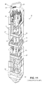
- FIG. 11 illustrates a typical boiling light water reactor nuclear fuel assembly and the many various components that go into making the assembly.
- a typical nuclear fuel assembly in a boiling light water nuclear reactor includes a lower tie plate 15, an upper tie plate 13 and a matrix of sealed nuclear fuel rods, both full length 11 and part-length 23, that are held in place by spacers 27 that help to retain a pair of central located water rods 29 supported between the upper and lower tie plates 13, 15.
- a square hollow channel 22 is used to surround the upper and lower tie plates 13, 15, spacers 27, water rods 29 and fuel rods 11, 23 that make up the nuclear fuel assembly 8.
- the upper tie plate has a bail handle 21 that is used to move the nuclear fuel assembly 8 within the reactor core.
- Each of the square hollow channels 22 is fitted with a single pair of channel clips 20 that are located on opposite corners of the channel 22.
- One of the two channel clips 20 is designed to have a single hole that allows a channel fastener to retain the channel 22 to the fuel bundle by a threaded post 31 located on one opposite corner of the upper tie plate 13.
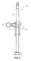
- FIGS. 1-5 illustrate a first embodiment of a channel-lifting tool 10 for lifting a channel on and off of a nuclear fuel bundle.
- the channel-lifting tool 10 includes a lifting bail 12, and a leg assembly 14 secured to the lifting bail 12.
- the leg assembly 14 includes a stationary leg 16 including a lifting foot 17 at an end thereof and a movable leg 18 including a lifting foot 19 at an end thereof.
- the lifting feet 17, 19 are selectively engageable with channel clips 20 of a fuel bundle channel 22 and are preferably machined to be fork-like to fit around the upper tie plate 13 threaded support post 31.
- the lifting feet 17, 19 may also be forged and/or cast as shown in FIGS. 2 and 4 to more securely engage the channel clips 20 on the top of the channel 22.
- the lifting feet 17, 19 are designed so as to fit under the channel clips 20 to the inside corner areas of the channel 22.
- the cutouts (forks) in the lifting feet of the channel-lifting tool 10 allow the tooling to surround three sides of the upper tie plate supporting post 31 located on the upper tie plate 13 and used to secure the channel 22 to the fuel assembly 8.
- the movable leg 18 is pivotable relative to the stationary leg 16 via a pivot 24.
- a locking leg 25 is disposed substantially perpendicular to the movable leg 18 and is fixed to the movable leg 18.
- An end of the locking leg 25 opposite from the pivot 24 is lockable to a leg locking section of the lifting bail 12 via a locking mechanism 26.
- the locking mechanism 26 includes a spring biased locking pin 28, which is biased toward engagement with a pin aperture 30 in the leg locking section of the lifting bail 12.
- the spring biased locking pin 28 In the locked position, the spring biased locking pin 28 preferably extends substantially the entire way through the lifting bail 12, and an opening through the lifting bail 12 provides a visual acknowledgement that the locking pin 28 is in the locked position when substantially flush to the opposite side of the channel-lifting tool 10.
- a ring 32 or other suitable structure enables an operator to pull the spring biased locking pin 28 against a force of a biasing spring 34.
- the movable leg 18 is pivotable relative to the lifting bail 12 and the stationary leg 16. See, for example, FIGS. 3 and 4 .
- the channel-lifting tool 10 has a narrower width with the movable leg 18 pivoted closer to the stationary leg 16. With the narrower width, the channel-lifting tool 10 is insertable into the channel 22 and under the channel clips 20. Once inserted, the movable leg 18 is pivoted (clockwise in FIGS. 1 and 2 ) until the locking mechanism 26 engages the pin aperture 30 ( FIG. 3 ) in the lifting bail 12 to lock the movable leg 18 in the lifting position as shown in FIGS. 1 and 2 . In this position, the lifting feet 17, 19 have a wider width and engage the channel clips 20 for safe lifting of the channel 22. A crane or the like is securable to a gripping section of the lifting bail 12 as part of the channel-lifting tool 10.
- the channel-lifting tool 10 has be orientated to the channel clip 20 that has a single hole, which is aligned with the movable leg 18 of the channel-lifting tool 10, prior to placing the tool under the two channel clips 20 on the top side of the channel 22. This is preferable because once the channel 22 is lifted into the air and above the fuel bundle, it is difficult to see the channel clip 20 with the hole that must be aligned with the threaded support post 31 on the upper tie plate 13, in order to secure the channel 22 to the fuel bundle using the channel fastener that has a male threaded like end plug that secures the channel to the fuel bundle.
- the leg assembly 14 is insertable within the channel 22, in a pre-aligned ordination position with the leg assembly 14 lockable in the lifting position with the location of the channel clip 20 that has a single hole for receiving the channel fastener.
- a length of the leg assembly 14 is preferably greater than a height of the bail handle 21 on the upper tie plate 13 of the nuclear fuel bundle.
- the channel-lifting tool 10 can remain in place and support the channel 22 until the channel 22 is fully seated on the fuel bundle without the aid of additional operators.
- FIGS. 6-10 illustrate an alternative embodiment of the channel-lifting tool.
- the channel-lifting tool 110 similarly includes a lifting bail 112 and a leg assembly 114.
- the leg assembly 114 includes lifting legs 116, 118, both of which in this embodiment are stationary to the lifting bail 112.
- a lifting foot 117 and a movable lifting foot 119 are similarly provided at distal ends of the lifting legs 116, 118, respectively.
- a movable lifting foot 119 is displaceable via sliding or the like between a lifting position ( FIGS. 6 and 7 ) and a pre-lifting position ( FIGS. 8 and 9 ).
- the movable lifting foot 119 is lockable in the lifting position by a locking mechanism 126.
- the locking mechanism 126 includes a spring biased locking pin 128 engageable with an opening 130 in the movable lifting foot 119.
- a release mechanism 132 is secured to the spring biased locking pin 128 and can be manually pulled to release the spring biased locking pin 128 from the aperture 130 in the movable lifting foot 119.
- the movable lifting foot 119 can be slid or otherwise displaced relative to the lifting leg 118.
- the lifting legs 116, 118 have a width that is narrow enough to be fit within the channel.
- the movable lifting foot 119 is shifted and locked in the lifting position into engagement with the channel clip 20. Once locked, the lifting tool 110 can be used for lifting a channel onto a fuel bundle and/or off a nuclear fuel assembly 8.
- the channel setting process in assembling a nuclear fuel assembly is made easier. Additionally, manual lifting of the channel by additional operators is no longer required, thereby improving operator safety. Moreover, scratching and/or marking of the channel surfaces and the possibility of distorting the channel are prevented and eliminated by the use of this tool.
Landscapes
- Physics & Mathematics (AREA)
- Engineering & Computer Science (AREA)
- Plasma & Fusion (AREA)
- General Engineering & Computer Science (AREA)
- High Energy & Nuclear Physics (AREA)
- Monitoring And Testing Of Nuclear Reactors (AREA)
- Load-Engaging Elements For Cranes (AREA)
Applications Claiming Priority (1)
| Application Number | Priority Date | Filing Date | Title |
|---|---|---|---|
| US11/955,701 US20110216871A1 (en) | 2007-12-13 | 2007-12-13 | Channel-Lifting Tool and Method |
Publications (3)
| Publication Number | Publication Date |
|---|---|
| EP2071582A2 true EP2071582A2 (fr) | 2009-06-17 |
| EP2071582A3 EP2071582A3 (fr) | 2011-07-20 |
| EP2071582B1 EP2071582B1 (fr) | 2014-02-26 |
Family
ID=40445282
Family Applications (1)
| Application Number | Title | Priority Date | Filing Date |
|---|---|---|---|
| EP08170545.1A Not-in-force EP2071582B1 (fr) | 2007-12-13 | 2008-12-03 | Outil et procédé de levage de canal |
Country Status (5)
| Country | Link |
|---|---|
| US (1) | US20110216871A1 (fr) |
| EP (1) | EP2071582B1 (fr) |
| JP (1) | JP2009145335A (fr) |
| ES (1) | ES2454241T3 (fr) |
| TW (1) | TWI456590B (fr) |
Cited By (1)
| Publication number | Priority date | Publication date | Assignee | Title |
|---|---|---|---|---|
| CN110718311A (zh) * | 2019-10-10 | 2020-01-21 | 中国科学院近代物理研究所 | 一种用于铅基反应堆燃料组件的换料抓头机构 |
Families Citing this family (2)
| Publication number | Priority date | Publication date | Assignee | Title |
|---|---|---|---|---|
| US20180161944A1 (en) * | 2016-12-09 | 2018-06-14 | Ge-Hitachi Nuclear Energy Americas Llc | Systems and methods for nuclear reactor dry tube assembly removal and installation |
| KR101987105B1 (ko) * | 2017-08-30 | 2019-06-11 | 한국원자력연구원 | 판형 핵연료 집합체 가공용 고정구 및 이를 이용한 판형 핵연료 집합체의 가공방법 |
Family Cites Families (4)
| Publication number | Priority date | Publication date | Assignee | Title |
|---|---|---|---|---|
| US5064606A (en) * | 1990-03-21 | 1991-11-12 | Gotech, Limited | Channel box removing apparatus |
| JP2555540B2 (ja) * | 1993-12-10 | 1996-11-20 | 有限会社ゴーテック | 核燃料集合体組立て用チャネルボックス吊り具 |
| JP2528786B2 (ja) * | 1993-12-10 | 1996-08-28 | 有限会社ゴーテック | 核燃料集合体組立て用チャネルボックス吊り具 |
| US5420899A (en) * | 1994-05-23 | 1995-05-30 | Apple, Jr.; Edward G. | Grapple for a fuel bundle channel |
-
2007
- 2007-12-13 US US11/955,701 patent/US20110216871A1/en not_active Abandoned
-
2008
- 2008-12-03 ES ES08170545.1T patent/ES2454241T3/es active Active
- 2008-12-03 EP EP08170545.1A patent/EP2071582B1/fr not_active Not-in-force
- 2008-12-09 JP JP2008312795A patent/JP2009145335A/ja active Pending
- 2008-12-11 TW TW097148284A patent/TWI456590B/zh not_active IP Right Cessation
Non-Patent Citations (1)
| Title |
|---|
| None |
Cited By (2)
| Publication number | Priority date | Publication date | Assignee | Title |
|---|---|---|---|---|
| CN110718311A (zh) * | 2019-10-10 | 2020-01-21 | 中国科学院近代物理研究所 | 一种用于铅基反应堆燃料组件的换料抓头机构 |
| CN110718311B (zh) * | 2019-10-10 | 2020-07-07 | 中国科学院近代物理研究所 | 一种用于铅基反应堆燃料组件的换料抓头机构 |
Also Published As
| Publication number | Publication date |
|---|---|
| TWI456590B (zh) | 2014-10-11 |
| EP2071582B1 (fr) | 2014-02-26 |
| ES2454241T3 (es) | 2014-04-10 |
| EP2071582A3 (fr) | 2011-07-20 |
| JP2009145335A (ja) | 2009-07-02 |
| TW200941501A (en) | 2009-10-01 |
| US20110216871A1 (en) | 2011-09-08 |
Similar Documents
| Publication | Publication Date | Title |
|---|---|---|
| KR101799130B1 (ko) | 원자로 헤드 내진 지지 타이 로드 시스템 | |
| EP2071582A2 (fr) | Outil et procédé de levage de canal | |
| TW201327577A (zh) | 核子反應爐補充燃料方法及裝置 | |
| JP2008216246A (ja) | 核燃料集合体内で燃料棒を位置合せしかつ操作するためのシステム | |
| CN105023623B (zh) | 核燃料组件修复装置及方法 | |
| CN102376375B (zh) | 一种用于抓取核燃料组件端部配件的水下操作装置 | |
| KR101227019B1 (ko) | 제어봉 구동축 취급 장치 | |
| JPH0422478B2 (fr) | ||
| JPS61176883A (ja) | 燃料集合体用のロツク管取外し装置 | |
| EP0327055B1 (fr) | Outil de manutention pour saisir un assemblage combustible nucléaire | |
| CN204792008U (zh) | 燃料棒永久储存容器 | |
| US5420899A (en) | Grapple for a fuel bundle channel | |
| CN207781215U (zh) | 核电站换料机夹爪检修装置 | |
| JP4965070B2 (ja) | 燃料集合体ノズル交換用の工具と方法 | |
| CN221876356U (zh) | 一种核反应堆驱动杆组件专用吊装装置 | |
| JPS6032839B2 (ja) | 制御棒を炉心から抜き出すためのリフト具 | |
| JP5432217B2 (ja) | 鋳鉄管の接続強度の試験機およびその試験方法 | |
| JPH0731274B2 (ja) | 格子の混合羽根の整直方法及び装置 | |
| KR102942708B1 (ko) | 상부 안내 구조물 인양볼트 안전 핸들링 기구 | |
| CN220840108U (zh) | 用于变速箱托架的安装支架 | |
| KR100216503B1 (ko) | 핵연료 취급 장치 | |
| JP2003177197A (ja) | 原子炉構造物の交換方法および交換装置 | |
| US6310930B1 (en) | Methods for guiding a fuel bundle into a channel | |
| CN222396800U (zh) | 一种锁紧机构及铁塔防护装置 | |
| CN217734938U (zh) | 用于建筑施工的防护网 |
Legal Events
| Date | Code | Title | Description |
|---|---|---|---|
| PUAI | Public reference made under article 153(3) epc to a published international application that has entered the european phase |
Free format text: ORIGINAL CODE: 0009012 |
|
| AK | Designated contracting states |
Kind code of ref document: A2 Designated state(s): AT BE BG CH CY CZ DE DK EE ES FI FR GB GR HR HU IE IS IT LI LT LU LV MC MT NL NO PL PT RO SE SI SK TR |
|
| AX | Request for extension of the european patent |
Extension state: AL BA MK RS |
|
| PUAL | Search report despatched |
Free format text: ORIGINAL CODE: 0009013 |
|
| AK | Designated contracting states |
Kind code of ref document: A3 Designated state(s): AT BE BG CH CY CZ DE DK EE ES FI FR GB GR HR HU IE IS IT LI LT LU LV MC MT NL NO PL PT RO SE SI SK TR |
|
| AX | Request for extension of the european patent |
Extension state: AL BA MK RS |
|
| RIC1 | Information provided on ipc code assigned before grant |
Ipc: G21C 3/33 20060101ALI20110614BHEP Ipc: G21C 19/105 20060101AFI20090325BHEP |
|
| 17P | Request for examination filed |
Effective date: 20120120 |
|
| AKX | Designation fees paid |
Designated state(s): CH DE ES FR LI |
|
| 17Q | First examination report despatched |
Effective date: 20120301 |
|
| GRAP | Despatch of communication of intention to grant a patent |
Free format text: ORIGINAL CODE: EPIDOSNIGR1 |
|
| RIC1 | Information provided on ipc code assigned before grant |
Ipc: G21C 19/105 20060101AFI20130723BHEP Ipc: G21C 3/33 20060101ALI20130723BHEP Ipc: G21C 1/08 20060101ALN20130723BHEP |
|
| RIC1 | Information provided on ipc code assigned before grant |
Ipc: G21C 1/08 20060101ALN20130809BHEP Ipc: G21C 3/33 20060101ALI20130809BHEP Ipc: G21C 19/105 20060101AFI20130809BHEP |
|
| INTG | Intention to grant announced |
Effective date: 20130826 |
|
| GRAS | Grant fee paid |
Free format text: ORIGINAL CODE: EPIDOSNIGR3 |
|
| GRAA | (expected) grant |
Free format text: ORIGINAL CODE: 0009210 |
|
| AK | Designated contracting states |
Kind code of ref document: B1 Designated state(s): CH DE ES FR LI |
|
| REG | Reference to a national code |
Ref country code: CH Ref legal event code: EP |
|
| REG | Reference to a national code |
Ref country code: DE Ref legal event code: R096 Ref document number: 602008030413 Country of ref document: DE Effective date: 20140410 Ref country code: ES Ref legal event code: FG2A Ref document number: 2454241 Country of ref document: ES Kind code of ref document: T3 Effective date: 20140410 |
|
| REG | Reference to a national code |
Ref country code: DE Ref legal event code: R097 Ref document number: 602008030413 Country of ref document: DE |
|
| PLBE | No opposition filed within time limit |
Free format text: ORIGINAL CODE: 0009261 |
|
| STAA | Information on the status of an ep patent application or granted ep patent |
Free format text: STATUS: NO OPPOSITION FILED WITHIN TIME LIMIT |
|
| 26N | No opposition filed |
Effective date: 20141127 |
|
| REG | Reference to a national code |
Ref country code: DE Ref legal event code: R097 Ref document number: 602008030413 Country of ref document: DE Effective date: 20141127 |
|
| REG | Reference to a national code |
Ref country code: DE Ref legal event code: R119 Ref document number: 602008030413 Country of ref document: DE |
|
| REG | Reference to a national code |
Ref country code: CH Ref legal event code: PL |
|
| REG | Reference to a national code |
Ref country code: FR Ref legal event code: ST Effective date: 20150831 |
|
| PG25 | Lapsed in a contracting state [announced via postgrant information from national office to epo] |
Ref country code: DE Free format text: LAPSE BECAUSE OF NON-PAYMENT OF DUE FEES Effective date: 20150701 Ref country code: CH Free format text: LAPSE BECAUSE OF NON-PAYMENT OF DUE FEES Effective date: 20141231 Ref country code: LI Free format text: LAPSE BECAUSE OF NON-PAYMENT OF DUE FEES Effective date: 20141231 |
|
| PG25 | Lapsed in a contracting state [announced via postgrant information from national office to epo] |
Ref country code: FR Free format text: LAPSE BECAUSE OF NON-PAYMENT OF DUE FEES Effective date: 20141231 |
|
| REG | Reference to a national code |
Ref country code: ES Ref legal event code: FD2A Effective date: 20160126 |
|
| PG25 | Lapsed in a contracting state [announced via postgrant information from national office to epo] |
Ref country code: ES Free format text: LAPSE BECAUSE OF NON-PAYMENT OF DUE FEES Effective date: 20141204 |