EP2071645A2 - Module piézoactionneur doté d'une construction multicouches de piézoactionneurs et son procédé de fabrication - Google Patents
Module piézoactionneur doté d'une construction multicouches de piézoactionneurs et son procédé de fabrication Download PDFInfo
- Publication number
- EP2071645A2 EP2071645A2 EP08105687A EP08105687A EP2071645A2 EP 2071645 A2 EP2071645 A2 EP 2071645A2 EP 08105687 A EP08105687 A EP 08105687A EP 08105687 A EP08105687 A EP 08105687A EP 2071645 A2 EP2071645 A2 EP 2071645A2
- Authority
- EP
- European Patent Office
- Prior art keywords
- piezoelectric actuator
- piezoelectric
- piezo
- actuator according
- layer
- Prior art date
- Legal status (The legal status is an assumption and is not a legal conclusion. Google has not performed a legal analysis and makes no representation as to the accuracy of the status listed.)
- Granted
Links
- 238000004519 manufacturing process Methods 0.000 title claims abstract description 6
- 238000000034 method Methods 0.000 title abstract description 7
- 238000000576 coating method Methods 0.000 claims abstract description 12
- 238000005245 sintering Methods 0.000 claims description 8
- 239000000463 material Substances 0.000 claims description 6
- 239000011248 coating agent Substances 0.000 claims description 4
- 238000002485 combustion reaction Methods 0.000 claims description 3
- 238000002347 injection Methods 0.000 claims description 3
- 239000007924 injection Substances 0.000 claims description 3
- 239000000446 fuel Substances 0.000 claims description 2
- 239000007769 metal material Substances 0.000 claims description 2
- 239000011368 organic material Substances 0.000 claims description 2
- 230000000694 effects Effects 0.000 description 5
- 238000000926 separation method Methods 0.000 description 4
- 230000005684 electric field Effects 0.000 description 3
- 238000002955 isolation Methods 0.000 description 3
- 230000015572 biosynthetic process Effects 0.000 description 2
- 239000000919 ceramic Substances 0.000 description 2
- 238000006243 chemical reaction Methods 0.000 description 2
- 238000010276 construction Methods 0.000 description 2
- 239000013078 crystal Substances 0.000 description 2
- 239000000126 substance Substances 0.000 description 2
- 239000011230 binding agent Substances 0.000 description 1
- 238000005336 cracking Methods 0.000 description 1
- 238000009434 installation Methods 0.000 description 1
- 230000009528 severe injury Effects 0.000 description 1
- 238000007493 shaping process Methods 0.000 description 1
- 239000000243 solution Substances 0.000 description 1
Images
Classifications
-
- H—ELECTRICITY
- H10—SEMICONDUCTOR DEVICES; ELECTRIC SOLID-STATE DEVICES NOT OTHERWISE PROVIDED FOR
- H10N—ELECTRIC SOLID-STATE DEVICES NOT OTHERWISE PROVIDED FOR
- H10N30/00—Piezoelectric or electrostrictive devices
- H10N30/50—Piezoelectric or electrostrictive devices having a stacked or multilayer structure
- H10N30/508—Piezoelectric or electrostrictive devices having a stacked or multilayer structure adapted for alleviating internal stress, e.g. cracking control layers
-
- H—ELECTRICITY
- H10—SEMICONDUCTOR DEVICES; ELECTRIC SOLID-STATE DEVICES NOT OTHERWISE PROVIDED FOR
- H10N—ELECTRIC SOLID-STATE DEVICES NOT OTHERWISE PROVIDED FOR
- H10N30/00—Piezoelectric or electrostrictive devices
- H10N30/01—Manufacture or treatment
- H10N30/05—Manufacture of multilayered piezoelectric or electrostrictive devices, or parts thereof, e.g. by stacking piezoelectric bodies and electrodes
- H10N30/053—Manufacture of multilayered piezoelectric or electrostrictive devices, or parts thereof, e.g. by stacking piezoelectric bodies and electrodes by integrally sintering piezoelectric or electrostrictive bodies and electrodes
Definitions
- the invention relates to a piezoelectric actuator with a multilayer structure of piezoelectric elements, for example for actuating a mechanical component such as a valve or the like, according to the preamble of claim 1 and a method for its production according to the method claim. 7
- the piezoelectric elements can be used so that by utilizing the so-called piezoelectric effect, a control of the needle stroke of a valve or the like can be made.
- the piezoelectric element is constructed of a material having a suitable crystal structure such that upon application of an external electrical voltage, a mechanical reaction of the piezoelectric element takes place, which represents a pressure or tension in a predeterminable direction as a function of the crystal structure and the contact regions of the electrical voltage.
- Such piezoelectric actuators are suitable, for example, for applications in which lifting movements take place under high operating forces and high clock frequencies.
- a piezoelectric actuator as part of a piezo injector from the DE 199 28 177 A1 known, which can be used to drive the nozzle needle at injectors for injection of fuel into the combustion chamber of an internal combustion engine.
- a piezoelectric element is constructed as a stack of a plurality of piezoceramic layers electrically coupled to one another, which is held under pretension between two stops.
- Each piezoceramic layer is enclosed as a piezoelectric layer between two internal electrodes, via which an electrical voltage can be applied externally. Due to this electrical voltage, the piezoceramic layers then each carry out small strokes in the direction of the potential gradient, which add up to the total stroke of the piezoelectric actuator. This Total stroke is variable by the amount of voltage applied and can be transferred to a mechanical actuator.
- a mutual lateral contacting of the internal electrodes via external electrodes is carried out, in which conductive surfaces are mounted on a respective side surface of the piezoelectric element, which are in contact with the respective internal electrodes.
- the invention is based on a piezoelectric actuator described in the introduction, which is provided with a multi-layer structure of piezoelectric elements and internal electrodes arranged between the piezoelectric layers of the piezoelectric elements.
- the inner electrodes are alternately applied in the direction of the layer structure of the piezoelectric element with a different polarity of an electrical voltage via a mutual lateral contact.
- at least one planar separating layer with predetermined coatings at least at the contacting of the internal electrodes is advantageously arranged at predetermined locations of the layer structure between the piezo elements.
- the coating consists preferably of organic or metallic material which is largely destructible by sintering the piezoelectric actuator.
- the areas of the coatings approximately cover the area from the outer surface of the piezoelectric actuator to the inner electrode, which is not contacted on this outer surface of the piezoelectric actuator, that is to say the region of the isolation zone.
- the inner electrodes adjacent to the respective separating layer each have the same polarity of the applied electrical voltage.
- the respective separating layer is produced by printing a respective adjacent piezoelectric element with the previously described material in the region of the coating, wherein the material is largely reduced during the sintering of the piezoelectric actuator.
- the separating layer In the area of the separating layer eliminates a negative or positive position, so that the separating layer is advantageously constructed between two gleichpoligen layers and thus no electric field between these layers or the respective inner electrodes is applied.
- the advantage of the invention lies in particular in the simple production of the separating layers with an increase in the robustness of the piezoactuators thus formed.
- the release liner is completely or partially removed depending on the chosen process or material. This takes place during the binder removal and / or sintering phase, so that the sintering in this area is completely or partially impeded; the separation effect thus changes in the mentioned predetermined breaking effect.
- this is preferably done by printing a preferably organic or metallic coating which is destroyed or removed in the course of sintering of the piezoelectric actuator so that no or at least no strong reduced bonding of the adjacent ceramic layers of the piezoelectric elements occurs in this region.
- the surface, the design and the layer thickness of the separating layer must be adapted to the respective material pairing of the piezo elements and the respective removal method become.
- the number of incorporated separation layers can range from at least one to the technically relevant number of known possible Hauptpolungsrissen. Their number is limited only by the tolerable loss of stroke of the piezoelectric actuator or by a possible corresponding extension of the piezoelectric actuator.
- the shape of the separating layer is in general, as described, adapted to the isolation zone, but also deviating designs depending on the geometry of the piezoelectric actuator bring about the desired effect.
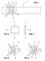
- FIG. 1 is a, for example, in principle from the above-mentioned prior art DE 199 28 177 A1 known piezoelectric actuator 1, which has piezoelectric elements 2 of piezoelectric layers or films, which cause a mechanical reaction of the piezoelectric actuator 1 in the direction of the layer structure by utilizing the piezoelectric effect when applying an electrical voltage to internal electrodes 3 and 4.
- the electrical voltage is brought to the piezoelectric actuator via outer electrodes, not shown here, for example with positive potential to the side up here with the internal electrodes 3 led out to the edge and with the negative potential to the side down here with the internal electrodes 4 led out to the edge , so that the inner electrodes 3 and 4 are thus alternately applied in the direction of the layer structure of the piezoelectric elements 2 with a different polarity of an electrical voltage.
- the piezoelectric actuator 1 can then be firmly embedded in a housing, for example the housing of an injection valve for motor vehicles for controlling the valve, via an actuator head and an actuator foot at the respective ends of the layer structure, and thus be part of a so-called piezo injector.
- FIG. 2 is the separating layer 6 according to the section after FIG. 1 shown in a plan view, in which case the two areas 7 and 8 are clearly visible.
- FIG. 3 shows the separating layer 6 with the areas 7 and 8 again in a section in an enlarged view.
- FIG. 4 is the section 5 after the FIG. 1 to illustrate the invention with a mechanical longitudinal crack 9 at the area 8 in the release layer 6, which can occur through the physical boundary condition mentioned in the introduction to the description.
- FIG. 5 is the section 5 after the FIG. 1 to illustrate the invention with two transversely extending from the region 8 of the separator layer 6 transverse to the internal electrodes 4 cracks 10, which may also occur by the physical boundary condition mentioned in the introduction.
- Such a transverse or oblique crack 10 in an extreme case, which runs in the direction of both adjacent internal electrodes 4, is defused by the fact that both adjacent internal electrodes 4 have the same potential and such a crack 10 can lead to no electrical flashover without an electric field.
Landscapes
- Engineering & Computer Science (AREA)
- Manufacturing & Machinery (AREA)
- Fuel-Injection Apparatus (AREA)
- General Electrical Machinery Utilizing Piezoelectricity, Electrostriction Or Magnetostriction (AREA)
Applications Claiming Priority (1)
| Application Number | Priority Date | Filing Date | Title |
|---|---|---|---|
| DE102007060167A DE102007060167A1 (de) | 2007-12-13 | 2007-12-13 | Piezoaktor mit einem Multilagenaufbau von Piezoelementen und ein Verfahren zu dessen Herstellung |
Publications (3)
| Publication Number | Publication Date |
|---|---|
| EP2071645A2 true EP2071645A2 (fr) | 2009-06-17 |
| EP2071645A3 EP2071645A3 (fr) | 2013-01-30 |
| EP2071645B1 EP2071645B1 (fr) | 2015-12-23 |
Family
ID=40510628
Family Applications (1)
| Application Number | Title | Priority Date | Filing Date |
|---|---|---|---|
| EP08105687.1A Not-in-force EP2071645B1 (fr) | 2007-12-13 | 2008-10-29 | Module piézoactionneur doté d'une construction multicouches de piézoactionneurs |
Country Status (2)
| Country | Link |
|---|---|
| EP (1) | EP2071645B1 (fr) |
| DE (1) | DE102007060167A1 (fr) |
Citations (1)
| Publication number | Priority date | Publication date | Assignee | Title |
|---|---|---|---|---|
| DE19928177A1 (de) | 1999-06-19 | 2001-01-11 | Bosch Gmbh Robert | Piezoaktor |
Family Cites Families (5)
| Publication number | Priority date | Publication date | Assignee | Title |
|---|---|---|---|---|
| DE10307825A1 (de) * | 2003-02-24 | 2004-09-09 | Epcos Ag | Elektrisches Vielschichtbauelement und Schichtstapel |
| JP4470504B2 (ja) * | 2004-02-03 | 2010-06-02 | 株式会社デンソー | 積層型圧電素子及びその製造方法 |
| DE102004031402A1 (de) * | 2004-06-29 | 2006-02-09 | Siemens Ag | Piezoelektrisches Bauteil mit Sollbruchstelle, Verfahren zum Herstellen des Bauteils und Verwendung des Bauteils |
| JP4706209B2 (ja) * | 2004-08-30 | 2011-06-22 | 株式会社デンソー | 積層型圧電体素子及びその製造方法並びに導電性接着剤 |
| WO2006073018A1 (fr) * | 2005-01-06 | 2006-07-13 | Murata Manufacturing Co., Ltd. | Procédé de fabrication d’actionneur piézoélectrique, et actionneur piézoélectrique |
-
2007
- 2007-12-13 DE DE102007060167A patent/DE102007060167A1/de not_active Withdrawn
-
2008
- 2008-10-29 EP EP08105687.1A patent/EP2071645B1/fr not_active Not-in-force
Patent Citations (1)
| Publication number | Priority date | Publication date | Assignee | Title |
|---|---|---|---|---|
| DE19928177A1 (de) | 1999-06-19 | 2001-01-11 | Bosch Gmbh Robert | Piezoaktor |
Also Published As
| Publication number | Publication date |
|---|---|
| EP2071645A3 (fr) | 2013-01-30 |
| DE102007060167A1 (de) | 2009-06-25 |
| EP2071645B1 (fr) | 2015-12-23 |
Similar Documents
| Publication | Publication Date | Title |
|---|---|---|
| EP1908132B1 (fr) | Actionneur piezo-electrique monolithe a rotation du sens de polarisation dans la zone de transition et utilisation dudit actionneur piezo-electrique | |
| EP2132796B1 (fr) | Composant piézoélectrique présentant une couche de sécurité et son procédé de réalisation | |
| EP2030263B1 (fr) | Actionneur piézoélectrique | |
| DE102008042232A1 (de) | Laminiertes piezoelektrisches Element und Verfahren, dieses herzustellen | |
| EP2030261B1 (fr) | Actionneur piézoélectrique | |
| DE102006026152A1 (de) | Anordnung mit einem beschichteten Piezoaktor | |
| EP2071645B1 (fr) | Module piézoactionneur doté d'une construction multicouches de piézoactionneurs | |
| DE102007058874A1 (de) | Piezoelektrisches Bauteil mit direkt strukturierter Außenkontaktierung, Verfahren zum Herstellen des Bauteils und Verwendung des Bauteils | |
| EP1503435B1 (fr) | Méthode de fabrication d'un actionneur piézo-électrique | |
| EP2798679B1 (fr) | Pile piézo-électrique avec passivation et procédé de passivation d'une pile piézo-électrique | |
| EP2417643B1 (fr) | Actionneur piézoélectrique et procédé de fabrication d'un actionneur piézoélectrique | |
| EP1981097B1 (fr) | Procédé de fabrication d'un actionneur piézoélectrique | |
| EP1909338B1 (fr) | Dispositif piézoactionneur avec une couche d'isolation | |
| EP1926156A2 (fr) | Piézoacteur doté de piézoéléments empilés les uns sur les autres | |
| EP3056724A1 (fr) | Injecteur de carburant et procede de fabrication d'un element piezoelectrique pour un injecteur de carburant | |
| EP1878907B1 (fr) | Soupape d'injection de combustible | |
| EP2149921B1 (fr) | Piézoactionneur doté de zones passives à la tête et/ou au pied | |
| EP2318687B1 (fr) | Actionneur piézoélectrique | |
| DE102006043709A1 (de) | Anordnung eines Piezoaktors in einem Gehäuse | |
| DE102007037552A1 (de) | Piezoelektrischer Aktor | |
| WO2017028985A1 (fr) | Composant piézoélectrique | |
| DE102009002313A1 (de) | Piezoelektrischer Aktor und Brennstoffeinspritzventil | |
| EP1767770A1 (fr) | Actionneur piézo-électrique | |
| DE102005040119A1 (de) | Piezoaktor mit innenliegender Kontaktierung | |
| DE102008000537A1 (de) | Piezoaktor |
Legal Events
| Date | Code | Title | Description |
|---|---|---|---|
| PUAI | Public reference made under article 153(3) epc to a published international application that has entered the european phase |
Free format text: ORIGINAL CODE: 0009012 |
|
| AK | Designated contracting states |
Kind code of ref document: A2 Designated state(s): AT BE BG CH CY CZ DE DK EE ES FI FR GB GR HR HU IE IS IT LI LT LU LV MC MT NL NO PL PT RO SE SI SK TR |
|
| AX | Request for extension of the european patent |
Extension state: AL BA MK RS |
|
| PUAL | Search report despatched |
Free format text: ORIGINAL CODE: 0009013 |
|
| AK | Designated contracting states |
Kind code of ref document: A3 Designated state(s): AT BE BG CH CY CZ DE DK EE ES FI FR GB GR HR HU IE IS IT LI LT LU LV MC MT NL NO PL PT RO SE SI SK TR |
|
| AX | Request for extension of the european patent |
Extension state: AL BA MK RS |
|
| RIC1 | Information provided on ipc code assigned before grant |
Ipc: H01L 41/083 20060101AFI20121224BHEP |
|
| 17P | Request for examination filed |
Effective date: 20130730 |
|
| RBV | Designated contracting states (corrected) |
Designated state(s): AT BE BG CH CY CZ DE DK EE ES FI FR GB GR HR HU IE IS IT LI LT LU LV MC MT NL NO PL PT RO SE SI SK TR |
|
| AKX | Designation fees paid |
Designated state(s): DE ES FR GB IT |
|
| 17Q | First examination report despatched |
Effective date: 20140728 |
|
| GRAP | Despatch of communication of intention to grant a patent |
Free format text: ORIGINAL CODE: EPIDOSNIGR1 |
|
| INTG | Intention to grant announced |
Effective date: 20150731 |
|
| GRAS | Grant fee paid |
Free format text: ORIGINAL CODE: EPIDOSNIGR3 |
|
| GRAA | (expected) grant |
Free format text: ORIGINAL CODE: 0009210 |
|
| AK | Designated contracting states |
Kind code of ref document: B1 Designated state(s): DE ES FR GB IT |
|
| REG | Reference to a national code |
Ref country code: GB Ref legal event code: FG4D Free format text: NOT ENGLISH |
|
| REG | Reference to a national code |
Ref country code: DE Ref legal event code: R096 Ref document number: 502008013687 Country of ref document: DE |
|
| PG25 | Lapsed in a contracting state [announced via postgrant information from national office to epo] |
Ref country code: IT Free format text: LAPSE BECAUSE OF FAILURE TO SUBMIT A TRANSLATION OF THE DESCRIPTION OR TO PAY THE FEE WITHIN THE PRESCRIBED TIME-LIMIT Effective date: 20151223 Ref country code: ES Free format text: LAPSE BECAUSE OF FAILURE TO SUBMIT A TRANSLATION OF THE DESCRIPTION OR TO PAY THE FEE WITHIN THE PRESCRIBED TIME-LIMIT Effective date: 20151223 |
|
| REG | Reference to a national code |
Ref country code: DE Ref legal event code: R097 Ref document number: 502008013687 Country of ref document: DE |
|
| PLBE | No opposition filed within time limit |
Free format text: ORIGINAL CODE: 0009261 |
|
| STAA | Information on the status of an ep patent application or granted ep patent |
Free format text: STATUS: NO OPPOSITION FILED WITHIN TIME LIMIT |
|
| 26N | No opposition filed |
Effective date: 20160926 |
|
| GBPC | Gb: european patent ceased through non-payment of renewal fee |
Effective date: 20161029 |
|
| REG | Reference to a national code |
Ref country code: FR Ref legal event code: ST Effective date: 20170630 |
|
| PG25 | Lapsed in a contracting state [announced via postgrant information from national office to epo] |
Ref country code: FR Free format text: LAPSE BECAUSE OF NON-PAYMENT OF DUE FEES Effective date: 20161102 Ref country code: GB Free format text: LAPSE BECAUSE OF NON-PAYMENT OF DUE FEES Effective date: 20161029 |
|
| PGFP | Annual fee paid to national office [announced via postgrant information from national office to epo] |
Ref country code: DE Payment date: 20191212 Year of fee payment: 12 |
|
| REG | Reference to a national code |
Ref country code: DE Ref legal event code: R119 Ref document number: 502008013687 Country of ref document: DE |
|
| PG25 | Lapsed in a contracting state [announced via postgrant information from national office to epo] |
Ref country code: DE Free format text: LAPSE BECAUSE OF NON-PAYMENT OF DUE FEES Effective date: 20210501 |