EP2071664A1 - Antenne, dispositif de communication, procédé de fabrication d'antenne - Google Patents
Antenne, dispositif de communication, procédé de fabrication d'antenne Download PDFInfo
- Publication number
- EP2071664A1 EP2071664A1 EP08253860A EP08253860A EP2071664A1 EP 2071664 A1 EP2071664 A1 EP 2071664A1 EP 08253860 A EP08253860 A EP 08253860A EP 08253860 A EP08253860 A EP 08253860A EP 2071664 A1 EP2071664 A1 EP 2071664A1
- Authority
- EP
- European Patent Office
- Prior art keywords
- coil
- antenna
- current
- standing wave
- winding wire
- Prior art date
- Legal status (The legal status is an assumption and is not a legal conclusion. Google has not performed a legal analysis and makes no representation as to the accuracy of the status listed.)
- Withdrawn
Links
Images

















Classifications
-
- H—ELECTRICITY
- H01—ELECTRIC ELEMENTS
- H01Q—ANTENNAS, i.e. RADIO AERIALS
- H01Q9/00—Electrically-short antennas having dimensions not more than twice the operating wavelength and consisting of conductive active radiating elements
- H01Q9/04—Resonant antennas
- H01Q9/16—Resonant antennas with feed intermediate between the extremities of the antenna, e.g. centre-fed dipole
- H01Q9/26—Resonant antennas with feed intermediate between the extremities of the antenna, e.g. centre-fed dipole with folded element or elements, the folded parts being spaced apart a small fraction of operating wavelength
- H01Q9/27—Spiral antennas
-
- H—ELECTRICITY
- H01—ELECTRIC ELEMENTS
- H01Q—ANTENNAS, i.e. RADIO AERIALS
- H01Q1/00—Details of, or arrangements associated with, antennas
- H01Q1/36—Structural form of radiating elements, e.g. cone, spiral, umbrella; Particular materials used therewith
-
- H—ELECTRICITY
- H01—ELECTRIC ELEMENTS
- H01Q—ANTENNAS, i.e. RADIO AERIALS
- H01Q1/00—Details of, or arrangements associated with, antennas
- H01Q1/12—Supports; Mounting means
- H01Q1/22—Supports; Mounting means by structural association with other equipment or articles
- H01Q1/24—Supports; Mounting means by structural association with other equipment or articles with receiving set
-
- H—ELECTRICITY
- H01—ELECTRIC ELEMENTS
- H01Q—ANTENNAS, i.e. RADIO AERIALS
- H01Q1/00—Details of, or arrangements associated with, antennas
- H01Q1/12—Supports; Mounting means
- H01Q1/22—Supports; Mounting means by structural association with other equipment or articles
- H01Q1/24—Supports; Mounting means by structural association with other equipment or articles with receiving set
- H01Q1/241—Supports; Mounting means by structural association with other equipment or articles with receiving set used in mobile communications, e.g. GSM
- H01Q1/242—Supports; Mounting means by structural association with other equipment or articles with receiving set used in mobile communications, e.g. GSM specially adapted for hand-held use
- H01Q1/243—Supports; Mounting means by structural association with other equipment or articles with receiving set used in mobile communications, e.g. GSM specially adapted for hand-held use with built-in antennas
-
- H—ELECTRICITY
- H01—ELECTRIC ELEMENTS
- H01Q—ANTENNAS, i.e. RADIO AERIALS
- H01Q9/00—Electrically-short antennas having dimensions not more than twice the operating wavelength and consisting of conductive active radiating elements
- H01Q9/04—Resonant antennas
- H01Q9/16—Resonant antennas with feed intermediate between the extremities of the antenna, e.g. centre-fed dipole
-
- H—ELECTRICITY
- H01—ELECTRIC ELEMENTS
- H01Q—ANTENNAS, i.e. RADIO AERIALS
- H01Q9/00—Electrically-short antennas having dimensions not more than twice the operating wavelength and consisting of conductive active radiating elements
- H01Q9/04—Resonant antennas
- H01Q9/30—Resonant antennas with feed to end of elongated active element, e.g. unipole
-
- Y—GENERAL TAGGING OF NEW TECHNOLOGICAL DEVELOPMENTS; GENERAL TAGGING OF CROSS-SECTIONAL TECHNOLOGIES SPANNING OVER SEVERAL SECTIONS OF THE IPC; TECHNICAL SUBJECTS COVERED BY FORMER USPC CROSS-REFERENCE ART COLLECTIONS [XRACs] AND DIGESTS
- Y10—TECHNICAL SUBJECTS COVERED BY FORMER USPC
- Y10T—TECHNICAL SUBJECTS COVERED BY FORMER US CLASSIFICATION
- Y10T29/00—Metal working
- Y10T29/49—Method of mechanical manufacture
- Y10T29/49002—Electrical device making
- Y10T29/49016—Antenna or wave energy "plumbing" making
Definitions
- the present invention contains subject matter related to Japanese Patent Application JP 2007-321251 filed in the Japan Patent Office on December 12, 2007, the entire contents of which being incorporated herein by reference.
- the present invention relates to an antenna, a communication device, and an antenna manufacturing method.
- wireless communication that uses various frequency bands is utilised.
- wireless communication it is important to reduce noise and thereby improve gain.
- various electronic devices have been developed and are used.
- a clock of a signal transmitted through electronic devices tends to have a higher frequency.
- various electric noises are generated from inside the electronic devices. These electric noises may interfere with wireless communication. Further, electric noise comes not only from outside a communication device that is performing wireless communication, but also electric noise is generated inside the communication device itself.
- a noise source in a communication device is located nearer than a transmitting side communication device of a received signal and other noise sources. Therefore, the communication device is likely to be affected by the influence of the noise generated inside the communication device. For example, a signal from an artificial satellite used for a global positioning system (GPS) has a low level, and influence of electric noise cannot be ignored.
- GPS global positioning system
- the magnetic current antenna detects a magnetic field in a transmitted electromagnetic wave. It is expected that an electric field is the main cause of the influence of electric noise generated inside the device. Because the magnetic current antenna detects a magnetic field, it is considered that the magnetic current antenna is unlikely to be affected by the influence of electric noise caused by an electric field. Examples of the magnetic current antenna include a very small loop antenna.
- the radiation element is very small as compared to the wavelength, and the ratio of radiation resistance to input resistance is low. Accordingly, efficiency in the entire antenna system of the magnetic current antenna is extremely low as compared to other antennas. Thus, although the magnetic current antenna is unlikely to be affected by the influence of electric noise, reception sensitivity of desired signals is reduced due to a reduction in antenna efficiency.
- the present invention addresses the issues described above and provides an antenna, a communication device, and an antenna manufacturing method that are new and improved and that make it possible to suppress the influence of electric noise without reducing antenna gain.
- an antenna that includes a coil that is formed such that one end of the coil is short circuited or open to a ground and a current standing wave is generated when a high frequency signal is applied to another end of the coil.
- the coil generates a magnetic field standing wave having a frequency corresponding to the high frequency signal, and thereby detects or radiates an electromagnetic wave having the frequency.
- a magnetic field of a signal (an electromagnetic wave) transmitted from a transmitter side when the coil is used for a receiving device, a magnetic field of a signal (an electromagnetic wave) transmitted from a transmitter side generates a magnetic field standing wave having the frequency of the magnetic field in the coil.
- the magnetic field standing wave causes the coil to generate a current standing wave.
- the current standing wave is output from the other end of the coil.
- the coil can detect a magnetic field while increasing gain, in the same manner that a dipole antenna that utilizes electric current detects an electric field while increasing gain.
- the coil when the coil is used for a transmitting device, the coil can generate a magnetic field in the opposite manner to the above.
- the coil may have an effective length that is an integral multiple of a quarter wavelength of the current standing wave.
- a winding wire of the coil may be wound in a turning direction so that directions of a magnetic field generated in the coil when the current standing wave is generated are the same.
- the winding wire of the coil may be wound in a turning direction that is reversed by setting a node in the magnetic field standing wave as a boundary. With this structure, the directions of the magnetic field in the coil can be aligned.
- One end of the coil may be short circuited to the ground, the coil may have an effective length that is a half wavelength of the current standing wave, and the winding wire of the coil may be wound in a turning direction that is reversed by setting a half point of an overall length of the winding wire as a boundary.
- the winding wire of the coil may be wound around a surface of a core having a high permeability or may be embedded in the core.
- a length of the winding wire of the coil may be adjusted to a length at which the current standing wave is generated when the high frequency signal is applied.
- a communication device that includes a coil that is formed such that one end of the coil is short circuited or open to a ground and a current standing wave is generated when a high frequency signal is applied to another end of the coil.
- the coil generates a magnetic field standing wave having a frequency corresponding to the high frequency signal, and thereby detects or radiates an electromagnetic wave having the frequency.
- an antenna manufacturing method that includes the steps of: short circuiting or opening one end of a coil serving as a radiation element to a ground; applying a high frequency signal to another end of the coil; and adjusting a length of a winding wire of the coil so that a current standing wave is generated in the coil by the high frequency signal.
- influence of electric noise can be suppressed without reducing antenna gain.
- a global positioning system is taken as an example of a communication system to which the antenna according to each embodiment of the present invention is applied.
- GPS global positioning system
- this example is not intended to limit the communication system to which the antenna according to each embodiment of the present invention is applied.
- the antenna according to each embodiment of the present invention can be applied to various communication systems.
- FIG. 1 is an explanatory diagram that illustrates a GPS that is an applied example of the antenna according to each embodiment of the present invention.
- an artificial satellite 10 transmits a signal (an electromagnetic wave) in the GPS.
- the electromagnetic wave can be regarded as a wave of an electric field E and a magnetic field H in the far field.
- Antennas are roughly classified, based on the reception principle, into a current antenna 11 (for example, a dipole antenna) that detects the electric field E and a magnetic current antenna 12 (for example, a very small loop antenna) that detects the magnetic field H.
- the current antenna 11 receives the electric field E of an electromagnetic wave, and also receives an electric noise N from an internal circuit 13 of a communication device in which the current antenna 11 itself is incorporated. Meanwhile, the magnetic current antenna 12 receives the magnetic field H of an electromagnetic wave, but is unlikely to receive the electric noise N.
- the electric noise Z is caused by a current flowing in the internal circuit 13. Therefore, the electric noise Z is mainly electric field noise, and includes little magnetic current noise.
- an electromagnetic field generated by the current antenna 11 is approximated as an infinitesimal electric dipole
- the electromagnetic field is expressed as the following Expressions 1A to 1C.
- r denotes a distance from the dipole
- ⁇ denotes an angle from the direction of an axis of the dipole
- ⁇ denotes a rotation angle about the axis of the dipole
- ⁇ denotes a dielectric constant
- 1 denotes a length of the dipole
- Q denotes the oscillation of an electric charge of the current dipole
- ⁇ denotes an angular frequency
- k denotes a wave number.
- an electric field E r denotes an electric field of a longitudinal wave generated from the dipole
- an electric field E ⁇ denotes an electric field of a transverse wave generated from the dipole
- a magnetic field H ⁇ denotes a magnetic field of a transverse wave generated around the dipole.
- the electric field E r and the electric field E ⁇ includes a term that is attenuated by the cube of the distance r, but the magnetic field H ⁇ does not include a term that is attenuated by the cube of the distance r. It is conceivable that an electromagnetic field generated by an infinitesimal electric dipole directly indicates the reception sensitivity of an electromagnetic wave of the infinitesimal electric dipole. Thus, from Expressions 1A to 1C, it is found that the reception sensitivity of the current antenna 11 is high with respect to the electric field E r and the electric field E ⁇ in the near field, but the reception sensitivity of the current antenna 11 is low with respect to the magnetic field H ⁇ in the near field.
- an electromagnetic field generated by the magnetic current antenna 12 is approximated as an infinitesimal magnetic dipole
- this electromagnetic field is expressed as the following Expressions 2A to 2C.
- r denotes a distance from the dipole
- ⁇ denotes an angle from the direction of an axis (a coil axis) of the dipole
- ⁇ denotes a rotation angle about the axis of the dipole
- ⁇ denotes permeability
- S denotes a cross sectional area of a coil
- I denotes a current flowing in the coil
- ⁇ denotes an angular frequency
- k denotes a wave number.
- a magnetic field H r denotes a magnetic field of a longitudinal wave generated from the dipole
- a magnetic field H ⁇ denotes a magnetic field of a transverse wave generated from the dipole
- an electric field E ⁇ denotes an electric field of a transverse wave generated around the dipole.
- H r IS 2 ⁇ ⁇ ⁇ e - jkr ⁇ 1 r 3 + jk r 2 cos ⁇ Expression 2 ⁇
- a H ⁇ IS 4 ⁇ ⁇ ⁇ e - jkr ⁇ 1 r 3 + jk r 2 - k 2 r sin ⁇ Expression 2 ⁇
- B H ⁇ - J ⁇ IS 4 ⁇ ⁇ ⁇ e - jkr ⁇ 1 r 2 - jk r sin ⁇ Expression 2 ⁇ C
- the magnetic field H r and the magnetic field H ⁇ include a term that is attenuated by the cube of the distance r, but the electric field E ⁇ does not include a term that is attenuated by the cube of the distance r.
- an electromagnetic field generated by an infinitesimal electric dipole directly indicates the reception sensitivity of an electromagnetic wave of the infinitesimal electric dipole.
- the magnetic current antenna 12 has lower reception sensitivity to an electric field in the near field as compared to the current antenna 11. Accordingly, it can be expected that the magnetic current antenna 12 receives radio waves in the far field, but has lower sensitivity to electric noise (an electric field) in the near field.
- the radiation element is very small as compared to the wavelength, and the ratio of the radiation resistance to the input resistance is low. As a result, efficiency of the entire antenna system of the very small loop antenna is low.
- a magnetic current antenna having a half wavelength radiation element can be fabricated in the same manner as is a normal current dipole antenna, while reducing the influence of electric noise by utilizing magnetic current, gain can be increased and efficiency of the entire antenna system can thereby be improved.
- the normal current dipole antenna by utilizing the fact that "electric charge (electron) that produces current” and an "electric conductor through which current flows" exist, the wavelength of the electric field or current is determined, and the radiation element is formed based on the wavelength.
- the present inventors identified the issues of the antenna according to the related art, and conducted painstaking research on an antenna that can obtain the above-described characteristics. As a result, the present inventors have conceived of the antenna according to each embodiment of the present invention. Next, the antenna that has been created as a result of the painstaking research conducted by the present inventors will be explained.
- FIG. 2A and FIG. 2B are explanatory diagrams each showing a displacement magnetic current that is used when the antenna according to each embodiment of the present invention is fabricated.
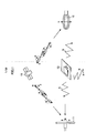
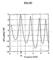
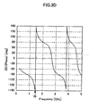
- the coil 23 shown in FIG. 3A was prepared, and characteristics of the coil 23 were measured. Measurement results are shown in FIG. 3B to FIG. 3D .
- FIG. 3A is an explanatory diagram that illustrates a coil whose characteristics were measured when the antenna according to each embodiment of the present invention was fabricated.
- FIG. 3B to FIG. 3D are diagrams each showing a measurement result of the characteristics of the coil shown in FIG. 3A .
- the coil 23 shown in FIG. 3A was formed such that a coil inner diameter ⁇ was set to 1mm, the number of turns to 36, and the coil length to 5mm.
- the coil 23 was placed on an upper surface of a substrate 25 having a bottom surface on which a tabular ground 24 is formed.
- the thickness of the substrate 25 was set to 0.8 mm.
- Ports P1 and P2 were formed using micro strip lines, as an input terminal (a feeding point) and an output terminal of the coil 23, respectively.
- S parameters were measured using the ports P1 and P2 as reference planes. Note that, in FIG. 3A , x1 denotes an end of the coil 23 on the port P1 side, and x2 denotes an end of the coil 23 on the port P2 side.
- the finite-length coil 23 behaves like a distributed constant circuit not like a lumped circuit, and the phase at the port P1 differs from the phase at the port P2. As shown in FIG. 3B and FIG. 3C , it is found from the measurement results of the S parameters that, at frequency f0, the phase of the coil 23 rotates by a half wavelength (180°) between the port P1 and the port P2.
- FIG. 3A conceptually shows the voltage V, the current I, the rate of change of the current dI/dt, and the displacement magnetic current I H that are generated in the coil 23. Note that each waveform shows a waveform at a predetermined time point, and time points of the respective waveforms are not the same (also in the measurement results of the characteristics, which will be described later). Due to this standing wave, the current I also forms a half wavelength standing wave. However, x1 and x2 of the standing wave of the current I are free ends.
- the phases of the current I1 at x1 and the current I2 at x2 are reversed.
- the rate of change of the current dI/dt takes the largest value at an anti-node of the standing wave of the current I, and takes the value of 0 at a node of the standing wave. Accordingly, the rate of change of the current dI/dt forms a half wavelength standing wave with x1 and x2 being free ends, like the current I.
- the displacement magnetic current I H is proportional to the rate of change of the current dI/dt. Therefore, it is conceivable that the displacement magnetic current I H also forms a half wavelength standing wave with x1 and x2 being free ends.
- the coil 23 that was formed and arranged as described above has an element length corresponding to a half wavelength, with respect to the displacement magnetic current I H at the frequency f0.
- This frequency f0 is defined as the resonance frequency with respect to the magnetic current.
- the resonance frequency f0 of the magnetic current is defined as described above.
- the next issue is how to determine the size of the coil 23 in order to adjust the resonance frequency f0 to a desired frequency.
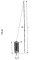
- FIG. 4A and FIG. 4B show the results of the measurements performed to determine the size of the coil 23.
- FIG. 4A and FIG. 4B are explanatory diagrams that illustrate a resonance frequency of the antenna according to each embodiment of the present invention.
- the resonance frequency f0 depends on, for example, the material and thickness of the winding wire of the coil 23. However, here, what influence the size of the coil 23 has on the resonance frequency f0 was measured.
- a copper wire of a thickness of 0.3 mm was used as a winding wire 26 of the coil 23.
- the winding wire 26 was wound around a cylinder to form the coil 23. Note that an inner diameter of the coil 23 is denoted as ⁇ .
- the inner diameter ⁇ of the coil 23 represents the diameter of the cylinder around which the winding wire 26 was wound.
- the pitch of the coil was set to 0.4 mm. Further, as shown in FIG. 4A , the resonance frequency f0 was measured while changing the overall length L of the winding wire 26. FIG. 4B shows the measurement results of the resonance frequency f0. As can be seen from FIG. 4B , the resonance frequency f0 does not significantly depends on the inner diameter ⁇ of the coil 23, while it significantly depends on the overall length L of the winding wire 26. It is found from the measurement results that, in order to form the coil 23 having an effective length corresponding to a desired resonance frequency, the overall length L of the winding wire 26 should be adjusted and determined so that the following Expression 5 is satisfied.
- the desired resonance frequency f0 namely, the resonance frequency that is desirably used for wireless communication is 1575 MHz, which is used for a GPS etc.
- the resonance frequency f0 is 1575 MHz
- the overall length L of the winding wire 26 is approximately 137 mm. This length is 1.4 times a half wavelength 95 mm of an electromagnetic wave of 1575 MHz in a free space.
- the resonance frequency f0 is not limited to 1575MHz. It is needless to say that the resonance frequency f0 may be set, for example, to the frequency that is used for wireless communication to which the antenna is applied.
- the value of the denominator constant (216) in Expression 5 also depends on the material and thickness of the winding wire and the coil pitch. Accordingly, the size of the coil 23 (the overall length L of the wining wire 26) is not limited to the above example, and is determined appropriately from the measurement results.
- the research findings of the present inventors make it possible to form the coil 23 that has an effective length corresponding to a desired resonance frequency f0. Then, based on the research findings, fabrication of a magnetic current antenna having an effective length corresponding to a quarter wavelength, and a magnetic current antenna having an effective length corresponding to a half wavelength will be described.
- FIG. 5A to FIG. 5C are explanatory diagrams that illustrate a resonance state of a quarter wavelength antenna according to each embodiment of the present invention
- one end (the port P2) of the coil 23 is open to a ground 24, and a high frequency signal is input and output through the other end (the port P1).
- x2 serves as a free end with respect to the voltage V, and serves as a fixed end with respect to the current I. Accordingly, x2 also serves as a fixed end with respect to the rate of change of the current dI/dt and the magnetic current I H .
- the input/output port x1 serves as a fixed end with respect to the voltage V, and serves as a free end with respect to other factors, i.e., the current I, the rate of change of the current dI/dt, and the magnetic current I H . Therefore, the mode of the standing wave occurring in the coil 23 is an odd number multiple of a quarter wavelength.
- FIG. 5B and FIG. 5C show measurement results of the resonance frequency f0.
- FIG. 5B and FIG. 5C show the measurement results of S11 (LogMag and Phase) of the S parameters, using the input/output port P1 as a reference plane.
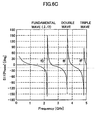
- FIG. 6A to FIG. 6C are explanatory diagrams that illustrate a resonance state of a half wavelength antenna according to each embodiment of the present invention.
- one end (the port P2) of the coil 23 is short circuited to the ground 24, and a high frequency signal is input and output through the other end (the port P1).
- x2 serves as a fixed end with respect to the voltage V (constantly 0V), and serves as a free end with respect to the current I. Accordingly, x2 also serves as a free end with respect to the rate of change of the current dI/dt and the magnetic current I H .
- the input/output port x1 serves as a fixed end with respect to the voltage V, and serves as a free end with respect to other factors, i.e., the current I, the rate of change of the current dI/dt, and the magnetic current I H . Therefore, the mode of the standing wave occurring in the coil 23 is an integral multiple of a half wavelength.
- FIG. 5B and FIG. 5C show measurement results of the resonance frequency f0.
- FIG. 5B and FIG. 5C show the measurement results of S11 (LogMag and Phase) of the S parameters, using the input/output port P1 as a reference plane.
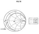
- a half wavelength magnetic current antenna (the coil 23) that resonates at 1575 MHz was fabricated as shown in FIG. 7A , and characteristics of the coil 23 were measured.
- FIG. 7B and FIG. 7C show measurement results of the input impedance when viewed from the feeding point at this time, and a standing wave ratio, respectively.
- the coil 23 in order to use the coil 23 as a radiation element of a magnetic current antenna, it is necessary to connect a high frequency signal line to the feeding point (the port 1).
- the impedance of a high frequency signal line such as a coaxial cable, is approximately 50 ⁇ . Therefore, it is necessary to reduce return loss by performing matching between the coil 23 and the signal line.
- a matching circuit 27 shown in FIG. 8A was connected to the feeding point.
- FIG.8A and FIG. 8C show the measurement results of the input impedance when viewed from the feeding point after connecting the matching circuit 27, and the standing wave ratio, respectively.
- the coil 23 having the diameter ⁇ of 2.6 mm was used, and the length of the coil 23 was set to 8 mm (18 turns). Further, the size of the ground substrate was set to 20 mm x 20 mm, and the thickness of the substrate was set to 0.8 mm.
- the VSWR in the vicinity of the resonance frequency f0 of 1575MHz becomes smaller than that before matching, and radiation efficiency is improved.
- the input impedance when viewed from the feeding point (the port P1) could be set to approximately 50 ⁇ at 1575MHz.
- this magnetic current antenna can be formed to be very small, as compared to a normal current antenna (a half wavelength dipole antenna, which has a half wavelength of 95 mm in the free space).
- the matching circuit 27 (refer to FIG. 8A ) shown here is only an example, and it is needless to say that any circuit can be used as long as matching can be performed. Although the matching circuit 27 is not shown below for convenience of explanation, it is assumed that the matching circuit 27 is connected to a feeding point in the measurements described later.
- FIG. 9A is an explanatory diagram that illustrates a coil whose radiation gain was measured when the antenna according to each embodiment of the present invention was fabricated.
- FIG. 9B to FIG. 9E are diagrams each showing a measurement result of the radiation gain of the coil shown in FIG. 9A .
- FIG. 10 is an explanatory diagram that illustrates a magnetic current direction of the half wavelength antenna according to each embodiment of the present invention.
- the magnetic current I H generated by the coil 23 has a waveform of a half wavelength.
- the ends x1 and x2 of the coil 23 become anti-nodes of the magnetic current I H , and a center O of the coil 23 becomes a node of the magnetic current I H .
- the direction of the magnetic current I H is reversed with the node serving as a boundary. Accordingly, it can be understood that an upper half of the magnetic current I H and a lower half of the magnetic current I H cancel each other out, with the center O of the coil 23 serving as the boundary.
- a normal current antenna for example, a dipole antenna
- the present inventors conceived of the idea that the direction of the magnetic current I H can be controlled by changing the turning direction of the coil 23 (the winding direction of the winding wire 26), and further improved the coil 23.
- the present inventors fabricated an antenna 100 according to a first embodiment of the present invention. Next, the antenna 100 will be described.
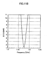
- FIG. 11A is an explanatory diagram that illustrates the antenna 100 according to the first embodiment of the present invention.
- FIG. 11B is a diagram that shows a measurement result of a standing wave ratio of the antenna 100 shown in FIG. 11A .
- the antenna 100 includes a coil 31 and a matching circuit 32.
- one end (on the port P2 side) of the coil 31 is short-circuited, and the overall length L of the winding wire 26 is determined so that the coil 31 has an effective length corresponding to a half wavelength.
- the matching circuit 32 is connected to the other end of the coil 31.
- the matching circuit 32 is formed to adjust an input impedance of the coil 31, in the same manner as in the above-described matching circuit 27.
- the coil 31 is placed on the substrate 25 that has a bottom surface on which the ground 24 is formed, and is connected to the port P1 (not shown in the figures) having one end formed with a micro strip line.
- the coil 31 is formed such that the winding wire 26 is wound in a turning direction that is reversed, with the center O of the coil 31, namely, the half point of the winding wire 26, serving as a boundary. That is, the coil 31 is formed by reversing the turning direction at the center of the coil 31.
- the number of turns was 18, and the turning direction of the winding wire 26 was all the same.
- the coil 31 of the present embodiment is formed such that, if the number of turns of the coil 31 is 18, the winding wire 26 is wound in the clockwise direction 9 times to the half point, and the remaining half thereof is wound in the counterclockwise direction 9 times.
- the coil 31 is formed by reversing the winding direction of the coil 23 shown in FIG. 10 , using the node position of the standing wave of the magnetic current I H as the boundary.
- the coil 31 can also be formed by connecting in series two coils that have opposite turning directions. However, it is preferable that two coils are connected such that their coil axes are aligned on the same straight line.
- a standing wave of the magnetic current I H occurs in the coil 31, in the same manner as in the coil 23.
- the directions of the magnetic current I H namely, the directions of the magnetic field H
- the directions of the magnetic current I H can be aligned by reversing the turning direction of the coil 31 using the node position of the magnetic current I H as the boundary.
- the coil 31 can inhibit the cancelling out of the magnetic current I H in the coil 31.
- radiation efficiency can further be improved.
- the antenna 100 utilizes the magnetic current I H . Accordingly, even if the antenna 100 is arranged near the metal plate such that the direction of the magnetic current I H is in parallel with the metal plate, magnetic current does not flow on the metal plate. Therefore, the operation of the antenna is not interfered with. Thus, the antenna 100 can be arranged close to the ground 24 in parallel therewith. Therefore, the antenna 100 makes it possible to reduce the size of the entire system.
- FIG. 12A is an explanatory diagram that illustrates an arrangement when a radiation gain of the antenna 100 according to the first embodiment of the present invention is measured.
- FIG. 12B to FIG. 12E are diagrams each showing a measurement result of the radiation gain of the antenna 100 shown in FIG. 12A
- the coil axis of the coil 31 provided in the antenna 100 of the present embodiment was vertically aligned and taken as the Z axis, the direction extending vertically from the substrate 25 toward the coil 31 was taken as the X axis, and the direction perpendicular to the Z axis and the X axis was taken as the Y axis.
- the coil 31 also operates as a radiation element, and is able to radiate an electromagnetic wave of the resonance frequency f0 (1575 MHz) as shown in FIG. 12B to FIG. 12E .
- the radiation gain of the coil 31 can be improved by 4 to 5 dB as compared to that of the coil 23, by reversing the turning direction of the coil 31 at the center thereof.
- the present inventors further conducted painstaking research to further improve the radiation gain of the antenna 100 according to the present embodiment.
- an antenna 200 according to a second embodiment of the present invention was fabricated. Next, the antenna 200 will be described.
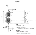
- FIG. 13A is an explanatory diagram that illustrates the antenna 200 according to the second embodiment of the present invention.
- FIG. 13B is a diagram that shows a measurement result of a standing wave ratio of the antenna 200 shown in FIG. 13A .
- the antenna 200 includes a coil 41 and a matching circuit 42.
- the coil 41 is formed by extending the coil length L (namely, the element length, refer to FIG. 4A ) of the coil 31 provided in the antenna 100 according to the first embodiment. More specifically, the coil 41 is formed by enlarging the pitch of the coil 31 to elongate the radiation element, without changing the inner diameter ⁇ of the coil 31. Therefore, the number of turns of the coil 41 was set to 16 (18 in the coil 31). That is, the coil 41 is formed such that the winding wire 26 is wound in the clockwise direction 8 times to the half point, and the remaining half thereof is wound in the counterclockwise direction 8 times. Further, the matching circuit 42 is formed to adjust an input impedance of the coil 41, in the same manner as in the above-described matching circuit 27.
- the other structural elements of the antenna 200 according to the second embodiment are the same as those of the antenna 100 according to the first embodiment. Therefore, a detailed explanation thereof is omitted.
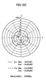
- FIG. 14A is an explanatory diagram that illustrates an arrangement when a radiation gain of the antenna 200 according to the second embodiment of the present invention is measured.
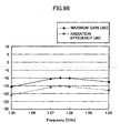
- FIG. 14B to FIG. 14E are diagrams each showing a measurement result of the radiation gain of the antenna 200 shown in FIG. 14A .
- the coil axis of the coil 41 provided in the antenna 200 of the present embodiment was vertically aligned and taken as the Z axis, the direction extending vertically from the substrate 25 toward the coil 41 was taken as the X axis, and the direction perpendicular to the Z axis and the X axis was taken as the Y axis.
- the coil 41 also operates as a radiation element, and is able to radiate an electromagnetic wave of the resonance frequency f0 (1575 MHz) as shown in FIG. 14B to FIG. 14E .
- the radiation gain of the coil 41 can be improved by 2 to 3 dB as compared to that of the coil 31, by forming the coil 41 to be 1.5 times longer than the coil length L of the coil 31.
- Performance of the antenna 200 according to the present embodiment In order to measure the performance of the antenna 200 of the present embodiment fabricated as described above, the antenna 200 was installed in a commercially available GPS receiver, and comparative experiments were carried out to compare the antenna 200 with a patch antenna of the related art that was originally installed in the GPS receiver.
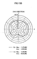
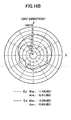
- FIG. 15A and FIG. 15B each show the radiation gain in this case. Note that, in order to install the antenna 200 in the GPS receiver, the antenna 200 was arranged such that the coil 41 was laid down and the coil axis was directed in the horizontal direction (the X axis direction). On the other hand, FIG. 16A and FIG. 16B each show a radiation gain of the patch antenna originally installed in the GPS receiver.
- a 50 ⁇ terminal, a low noise amplifier (LNA) having a gain of 23.7 dB and a noise figure (NF) of 1.4 dB, and a spectrum analyzer were connected in series without connecting the antenna, and the noise floor of the spectrum analyzer at 1575.4 MHz was measured.
- the noise floor was -117 dBm.
- the antenna 200 or the patch antenna was connected instead of the 50 ⁇ terminal, and the noise floor of the spectrum analyzer was measured in the same manner.
- the noise floor was -114 dBm in the case of the patch antenna, and -116 dBm in the case of the antenna 200. From this result, it is found that the antenna 200 improved sensitivity to background noise by 2dB as compared to the patch antenna.
- the noise floor of the spectrum analyzer was measured in the same manner.
- the noise floor was -109 dBm in the case of the patch antenna, and -115 dBm in the case of the antenna 200. From this result, it is found that the antenna 200 improved sensitivity to background noise including electric noise in the device by 6dB as compared to the patch antenna.
- the increase in the noise floor of the antenna 200 is smaller than that of the patch antenna. In other words, the antenna 200 is less affected by the influence of electric noise.
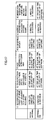
- FIG. 17 shows the results.
- the antenna 200 can shorten the time required for the positioning of the current position as compared to the patch antenna.
- the antenna 200 can capture the artificial satellite 10 even in a position where the patch antenna cannot capture the artificial satellite 10.
- the radiation gain of the antenna 200 was substantially the same as that of the patch antenna. Therefore, it is also found from the measurement results shown in FIG. 17 that the antenna 200 is less affected by the influence of electric noise as compared to the patch antenna.
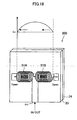
- An antenna 300 shown in FIG. 18 can be fabricated, for example, as a magnetic current antenna having an effective wavelength of a half wavelength.
- the antenna 300 includes two coils 51A and 51B.
- Each of the coils 51A and 51B has an effective length corresponding to a quarter wavelength with respect to the resonance frequency f0.
- Each of the coils 51A and 51B is formed using the method described in relation to the coil 23.
- the coils 51A and 51B are connected such that turning directions thereof are reversed from each other when viewed from a feeding point, and the coil axes are aligned on the same straight line.
- the feeding point of the antenna 300 is set to the connection point between the coils 51A and 51B. Further, ends of the coils 51A and 51B that are opposite to the feeding point are open to the ground 24.
- the coils 51A and 51B can operate as radiation elements having an effective length that is a half wavelength of the magnetic current I H .
- the coils 51A and 51B are separately formed and connected. However, it is apparent that they may be formed integrally.
- the antennas 100 and 200 having an effective length corresponding to a half wavelength are described.
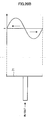
- the antenna 400 includes the coil 51A.
- the coil 51A has an effective length corresponding to a quarter wavelength with respect to the resonance frequency f0. In this case, because the direction of the magnetic current I H is constant in the coil 51A, there is no need to reverse the turning direction of the coil.
- the coil 51A can operate as a radiation element having an effective length that is a quarter wavelength of the magnetic current I H .
- the antenna 500 includes a coil 61.
- the coil 61 is formed to have an effective length corresponding to one wavelength at the resonance frequency f0, using the method described in relation to the coil 23.
- the coil 61 is divided into 61A to 61C for every turning direction. More specifically, when the coil 61B has one turning direction (for example, clockwise), the other coils 61A and 61C have another turning direction (for example, counterclockwise). In other words, the turning direction of the coil 61 is reversed using nodes of the magnetic current I H as boundaries.
- the coil 61 can also be formed such that the coils 61A to 61C are formed separately and connected in series.
- the coil 61 can operate as a radiation element having an effective length that is one wavelength of the magnetic current I H . At this time, it is also possible to inhibit mutual cancellation of the magnetic current I H .
- the antenna 500 according to the third modified example can inhibit the mutual cancellation of the magnetic current I H , and also can have a longer radiation element, resulting in a further improved radiation gain.
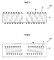
- the coil 41 may be formed by winding the winding wire 26 around a core 33 that is formed of a material having a high permeability, as shown in FIG. 21A .
- the coil 41 may be formed by embedding the winding wire 26 in a core 34 that is formed of a material having a high permeability, as shown in FIG. 21B .
- the magnitude of the displacement magnetic current I H generated in the coil 41 is proportional to the permeability of the core. Accordingly, with this structure, the gain of the antenna 200 can further be improved.
- the coil 41 according to the second embodiment is used as an example in FIG. 21A and FIG. 21B
- the coil of another embodiment or modified example can be used for antenna fabrication in the same manner.
- the antennas are mainly used for a receiving device (an example of a communication device). However, it will be obviously apparent that these antennas can be used for a transmitting device (an example of a communication device).
- the winding wire 26 is a copper wire.
- the coil may be formed by coating the surface of the winding wire 26 with an insulator. Coating of the winding wire 26 in this manner makes it possible to inhibit a change in resonance frequency due to a short circuit of the radiation element (coil) in the middle.
- the coil is placed on the substrate 25 having the bottom surface on which the ground 24 is formed.
- the present invention is not limited to this example.
- the coil may be placed directly on the ground 24 without interposing the substrate 25.
Landscapes
- Engineering & Computer Science (AREA)
- Computer Networks & Wireless Communication (AREA)
- Variable-Direction Aerials And Aerial Arrays (AREA)
- Details Of Aerials (AREA)
Applications Claiming Priority (1)
| Application Number | Priority Date | Filing Date | Title |
|---|---|---|---|
| JP2007321251A JP2009147556A (ja) | 2007-12-12 | 2007-12-12 | アンテナ、通信装置及びアンテナ製造方法 |
Publications (1)
| Publication Number | Publication Date |
|---|---|
| EP2071664A1 true EP2071664A1 (fr) | 2009-06-17 |
Family
ID=40510049
Family Applications (1)
| Application Number | Title | Priority Date | Filing Date |
|---|---|---|---|
| EP08253860A Withdrawn EP2071664A1 (fr) | 2007-12-12 | 2008-12-03 | Antenne, dispositif de communication, procédé de fabrication d'antenne |
Country Status (5)
| Country | Link |
|---|---|
| US (1) | US8599092B2 (fr) |
| EP (1) | EP2071664A1 (fr) |
| JP (1) | JP2009147556A (fr) |
| KR (1) | KR20090063139A (fr) |
| CN (1) | CN101459280A (fr) |
Cited By (1)
| Publication number | Priority date | Publication date | Assignee | Title |
|---|---|---|---|---|
| US11683073B2 (en) | 2018-08-10 | 2023-06-20 | Samsung Electronics Co., Ltd. | Human body communication apparatus for near field communication signal and method thereof |
Families Citing this family (7)
| Publication number | Priority date | Publication date | Assignee | Title |
|---|---|---|---|---|
| US9153855B2 (en) * | 2009-08-28 | 2015-10-06 | Panasonic Intellectual Property Management Co., Ltd. | Antenna, antenna unit, and communication device using them |
| JP2012039230A (ja) * | 2010-08-04 | 2012-02-23 | Mitsubishi Electric Corp | アンテナ装置 |
| CN108321542B (zh) * | 2015-06-12 | 2020-08-21 | Oppo广东移动通信有限公司 | 天线系统及应用该天线系统的通信终端 |
| DE102017200132A1 (de) | 2017-01-05 | 2018-07-05 | Fraunhofer-Gesellschaft zur Förderung der angewandten Forschung e.V. | Antennenvorrichtung mit Bonddrähten |
| DE102017200130A1 (de) | 2017-01-05 | 2018-07-05 | Fraunhofer-Gesellschaft zur Förderung der angewandten Forschung e.V. | Bändchenbondantennen |
| DE102017200131A1 (de) * | 2017-01-05 | 2018-07-05 | Fraunhofer-Gesellschaft zur Förderung der angewandten Forschung e.V. | Antennenvorrichtung, Antennenarray, elektrische Schaltung mit einer Antennenvorrichtung und Bändchenbondantenne |
| CN111490437A (zh) * | 2019-04-15 | 2020-08-04 | 中国科学院物理研究所 | 利用激光与天线靶作用诱导频率可控微波辐射的装置和方法 |
Citations (4)
| Publication number | Priority date | Publication date | Assignee | Title |
|---|---|---|---|---|
| US5006861A (en) | 1989-04-20 | 1991-04-09 | Motorola, Inc. | Antenna |
| JPH06237116A (ja) | 1993-02-10 | 1994-08-23 | Matsushita Electric Ind Co Ltd | 移動無線用アンテナ |
| WO1999003166A1 (fr) | 1997-07-09 | 1999-01-21 | Allgon Ab | Dispositif antenne destine a une unite de radiocommunication portable |
| US20030114118A1 (en) * | 2000-12-28 | 2003-06-19 | Susumu Fukushima | Antenna, and communication device using the same |
Family Cites Families (11)
| Publication number | Priority date | Publication date | Assignee | Title |
|---|---|---|---|---|
| US3049711A (en) * | 1958-11-12 | 1962-08-14 | Packard Bell Electronics Corp | Omni-directional portable antenna |
| JPH05183326A (ja) * | 1992-01-08 | 1993-07-23 | Matsushita Electric Ind Co Ltd | 移動無線用アンテナ |
| JP3362194B2 (ja) * | 1996-04-05 | 2003-01-07 | オムロン株式会社 | 送受信装置 |
| JP2996190B2 (ja) * | 1996-12-19 | 1999-12-27 | 株式会社村田製作所 | アンテナ装置 |
| DE19715726C2 (de) * | 1997-04-15 | 2001-08-30 | Siemens Ag | Antennenvorrichtung für Mobilfunkgeräte |
| US6164241A (en) * | 1998-06-30 | 2000-12-26 | Lam Research Corporation | Multiple coil antenna for inductively-coupled plasma generation systems |
| JP2000165175A (ja) * | 1998-11-27 | 2000-06-16 | Kyosan Electric Mfg Co Ltd | インピーダンス整合装置 |
| DE19900179C1 (de) * | 1999-01-07 | 2000-02-24 | Bosch Gmbh Robert | Plasmaätzanlage |
| JP2002204114A (ja) * | 2000-12-28 | 2002-07-19 | Matsushita Electric Ind Co Ltd | アンテナ装置およびそれを用いた通信機器 |
| US6664740B2 (en) * | 2001-02-01 | 2003-12-16 | The Regents Of The University Of California | Formation of a field reversed configuration for magnetic and electrostatic confinement of plasma |
| US6882242B2 (en) * | 2003-06-19 | 2005-04-19 | Radio Frequency Systems, Inc. | Frequency selective low loss transmission line system |
-
2007
- 2007-12-12 JP JP2007321251A patent/JP2009147556A/ja active Pending
-
2008
- 2008-12-03 EP EP08253860A patent/EP2071664A1/fr not_active Withdrawn
- 2008-12-04 US US12/328,045 patent/US8599092B2/en not_active Expired - Fee Related
- 2008-12-11 KR KR1020080125944A patent/KR20090063139A/ko not_active Withdrawn
- 2008-12-11 CN CNA2008101851528A patent/CN101459280A/zh active Pending
Patent Citations (4)
| Publication number | Priority date | Publication date | Assignee | Title |
|---|---|---|---|---|
| US5006861A (en) | 1989-04-20 | 1991-04-09 | Motorola, Inc. | Antenna |
| JPH06237116A (ja) | 1993-02-10 | 1994-08-23 | Matsushita Electric Ind Co Ltd | 移動無線用アンテナ |
| WO1999003166A1 (fr) | 1997-07-09 | 1999-01-21 | Allgon Ab | Dispositif antenne destine a une unite de radiocommunication portable |
| US20030114118A1 (en) * | 2000-12-28 | 2003-06-19 | Susumu Fukushima | Antenna, and communication device using the same |
Cited By (1)
| Publication number | Priority date | Publication date | Assignee | Title |
|---|---|---|---|---|
| US11683073B2 (en) | 2018-08-10 | 2023-06-20 | Samsung Electronics Co., Ltd. | Human body communication apparatus for near field communication signal and method thereof |
Also Published As
| Publication number | Publication date |
|---|---|
| US8599092B2 (en) | 2013-12-03 |
| CN101459280A (zh) | 2009-06-17 |
| US20090231227A1 (en) | 2009-09-17 |
| KR20090063139A (ko) | 2009-06-17 |
| JP2009147556A (ja) | 2009-07-02 |
Similar Documents
| Publication | Publication Date | Title |
|---|---|---|
| US8599092B2 (en) | Antenna, communication device, antenna manufacturing method | |
| JP6465109B2 (ja) | マルチアンテナ及びそれを備える無線装置 | |
| JP5323271B2 (ja) | アンテナ装置及び無線通信装置 | |
| US20140320367A1 (en) | SMALL PRINTED MEANDER ANTENNA PERFORMANCES IN 315MHz FREQUENCY BAND INCLUDING RF CABLE EFFECT | |
| KR20020033554A (ko) | 안테나 | |
| EP0870344B1 (fr) | Antenne helicoidale toroidale a contre-spiralage | |
| EP2666207B1 (fr) | Dispositif de communication et dispositif de poursuite avec antenne à fente et procédé correspondent | |
| JP5102941B2 (ja) | 広帯域アンテナ | |
| US20210257725A1 (en) | Coaxial helix antennas | |
| US20250279587A1 (en) | Ultra high frequency antenna with variable frequency range | |
| JP6977443B2 (ja) | 複合アンテナ装置 | |
| JP4249229B2 (ja) | アンテナ装置 | |
| JP5001218B2 (ja) | 軸モードヘリカルアンテナ | |
| US8648754B2 (en) | Multi-resonant broadband antenna | |
| JP2019062373A (ja) | 複合アンテナ装置 | |
| WO2024259969A9 (fr) | Ensemble antenne, dispositif de communication et véhicule | |
| JP2003069329A (ja) | アンテナ | |
| JP2006325093A (ja) | 携帯型無線機 | |
| US10714821B2 (en) | Antenna structure | |
| JP4637606B2 (ja) | 線状アンテナ | |
| Ismail et al. | DESIGN DIFFERENT DIMENTIONAL PATCH RECTANGULAR DIELECTRIC RESONATOR ANTENNA FOR 5G APPLICATION | |
| EP3024091A1 (fr) | Appareil radio | |
| Bank et al. | Antenna and Anti-antenna | |
| JP2022033013A (ja) | 同調アンテナを有するeLORAN受信機、および関連方法 | |
| Khatib | A Novel and an Efficient Design of an Inverted F-Antenna for Bluetooth Low Energy Communications |
Legal Events
| Date | Code | Title | Description |
|---|---|---|---|
| PUAI | Public reference made under article 153(3) epc to a published international application that has entered the european phase |
Free format text: ORIGINAL CODE: 0009012 |
|
| 17P | Request for examination filed |
Effective date: 20081220 |
|
| AK | Designated contracting states |
Kind code of ref document: A1 Designated state(s): AT BE BG CH CY CZ DE DK EE ES FI FR GB GR HR HU IE IS IT LI LT LU LV MC MT NL NO PL PT RO SE SI SK TR |
|
| AX | Request for extension of the european patent |
Extension state: AL BA MK RS |
|
| 17Q | First examination report despatched |
Effective date: 20090724 |
|
| AKX | Designation fees paid |
Designated state(s): DE FR GB |
|
| STAA | Information on the status of an ep patent application or granted ep patent |
Free format text: STATUS: THE APPLICATION IS DEEMED TO BE WITHDRAWN |
|
| 18D | Application deemed to be withdrawn |
Effective date: 20150701 |