EP2071786B1 - Verfahren und Sende-Empfänger zur Datenkommunikation - Google Patents
Verfahren und Sende-Empfänger zur Datenkommunikation Download PDFInfo
- Publication number
- EP2071786B1 EP2071786B1 EP08000707.3A EP08000707A EP2071786B1 EP 2071786 B1 EP2071786 B1 EP 2071786B1 EP 08000707 A EP08000707 A EP 08000707A EP 2071786 B1 EP2071786 B1 EP 2071786B1
- Authority
- EP
- European Patent Office
- Prior art keywords
- channel
- tap
- estimated
- blind
- data
- Prior art date
- Legal status (The legal status is an assumption and is not a legal conclusion. Google has not performed a legal analysis and makes no representation as to the accuracy of the status listed.)
- Active
Links
Images





Classifications
-
- H—ELECTRICITY
- H04—ELECTRIC COMMUNICATION TECHNIQUE
- H04L—TRANSMISSION OF DIGITAL INFORMATION, e.g. TELEGRAPHIC COMMUNICATION
- H04L25/00—Baseband systems
- H04L25/02—Details ; arrangements for supplying electrical power along data transmission lines
- H04L25/03—Shaping networks in transmitter or receiver, e.g. adaptive shaping networks
- H04L25/03006—Arrangements for removing intersymbol interference
- H04L25/03171—Arrangements involving maximum a posteriori probability [MAP] detection
-
- H—ELECTRICITY
- H04—ELECTRIC COMMUNICATION TECHNIQUE
- H04L—TRANSMISSION OF DIGITAL INFORMATION, e.g. TELEGRAPHIC COMMUNICATION
- H04L25/00—Baseband systems
- H04L25/02—Details ; arrangements for supplying electrical power along data transmission lines
- H04L25/0202—Channel estimation
- H04L25/0238—Channel estimation using blind estimation
-
- H—ELECTRICITY
- H04—ELECTRIC COMMUNICATION TECHNIQUE
- H04L—TRANSMISSION OF DIGITAL INFORMATION, e.g. TELEGRAPHIC COMMUNICATION
- H04L25/00—Baseband systems
- H04L25/02—Details ; arrangements for supplying electrical power along data transmission lines
- H04L25/0202—Channel estimation
- H04L25/0212—Channel estimation of impulse response
Definitions
- the present invention relates to a method and a transceiver for a data communication.
- the invention relates especially to a method and a transceiver for processing data for transmission in a wireless communication system using selective channel transmission.
- Multi-channel communication systems are known from the state of the art.
- They are used to increase transmission capacity for different types of information, especially data, voice, images and videos.
- Such a multi-channel system may be a multiple-input multiple-output (MIMO) communication system, an orthogonal frequency division modulation (OFDM) system, a MIMO system that utilizes OFDM, or some other types of system.
- MIMO multiple-input multiple-output
- OFDM orthogonal frequency division modulation
- a MIMO system employs multiple transmit antennas and multiple receive antennas to exploit spatial diversity to support a number of spatial sub channels, each of which may be used to transmit data.
- An OFDM System effectively partitions the operating frequency and into a number of frequency sub channels (or frequency bins), each of which is associated with a respective sub channel on which data may be modulated.
- a multi-channel communication system thus supports a number of "transmission" channels, each of which may correspond to a spatial sub channel in a MIMO system, a frequency sub channel in an OFDM system, or a spatial sub channel of a frequency sub channel in a MIMO system that utilizes OFDM.
- the transmission channels of a multi-channel communication system might experience different link conditions (e.g., due to different fading and multipath effects) and may achieve different signal-to-noise-plus-interference ratios (SNRs).
- SNRs signal-to-noise-plus-interference ratios
- the transmission capacities i.e., the information bit rates
- the link conditions typically vary over time.
- the bit rates supported by the transmission channels also vary with time.
- the different transmission capacities of the channels and the time-variant nature of these capacities make it challenging to provide an effective coding and modulation scheme.
- Turbo Equalization where a Soft Input Soft Output equalizer exchanges extrinsic information with a Soft Input Soft Output decoder.
- the Turbo Equalizer can mitigate completely the Intersymbol Interference (ISI) effect.
- ISI Intersymbol Interference
- the literature has assumed perfect knowledge of the impulse response of the multipath channel, which is not possible in practical applications.
- the channel's impulse response is estimated with the use of pilots, which might not be efficient in terms of spectral efficiency.
- blind channel estimation is used, the taps of the channel are estimated based on the properties of the transmitted signal.
- PAM modulation is considered for UWB transmission [9] and it is an intermediate stage of evolution for blind channel estimation of QAM signals since it can be decomposed into two independent PAM signals.
- the invention can be integrated into different communication and handling standards.
- a further preferred embodiment of the invention uses a 2 Q -order modulation with multilevel code transmission.
- a 2Q-PAM modulation with multilevel code transmission is utilized.
- Figure 1 shows a transmitter with Q levels. Each level q is independently encoded.
- First the vector of information bits b q [ b (1), whil, b q ( i ), whil,b q ( I )] T of the q -th level is encoded by an asymmetric code.
- the antipodal coded interleaved bits x q ( n ) are mapped by a multilevel modulator.
- the signal is composed by two levels which correspond to two BPSK signals as shown in Figure 2 .
- the first level has a minimum distance of 2d and the second one of d.
- Fig. 2 shows an example of a 4-PAM modulation with multilevel coding.
- the 4-PAM signal is the sum of the two BPSK signals and has a minimum distance of d.
- the received signal r ( k ) is detected by the Blind Turbo Equalizer.
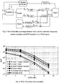
- Fig. 3 contains a schematic presentation of a preferred embodiment of the invention with a utilization of an equalizer and a channel estimator.
- Fig. 3 implements soft information exchange between the blind channel estimator, a frequency domain equalizer and a MAP decoder for a 4-PAM signal.
- Figure 3 depicts the iterative receiver of a 4-PAM signal as an example.
- the received signal is used for estimating the channel and for equalization.
- the equalizer with the demapper computes the extrinsic information of each level, L q , ext E x ( q denotes the level, E an output of the equalizer and extrinsic information ) . Any soft input or soft output equalizer can be used.
- the extrinsic information of each level, L q , ext E s is deinterleaved and used as a-priori information for the decoders (see Figure 3 ).
- Each decoder computes the a-posteriori information, L q D c , and the extrinsic information, L q , ext D c , of the coded bits.
- the interleaved extrinsic information of the coded bits is mapped and used as a-priori information of the equalizer and the a-posteriori value is used by the channel estimator. Notice that the total a-posteriori information of the decoder can be used for the channel estimator since the values of s are uncorrelated with the values of the a-priori information.
- the quality of the output of the equalizer the decoder and the channel estimator are refined until the system shows no improvement any more or the maximum number of iterations is reached.
- a further embodiment of the invention includes a blind channel estimation using code properties.
- This implementation includes an algorithm for blindly estimating the channel.
- a blind turbo equalizer is proposed using the statistics of the encoded signals for BPSK modulation.
- a slightly modified version of [6] is used for blind channel estimation.
- the channel encoder is symmetric (i.e. a code which can produce a valid codeword that is the negation of another codeword in the codeword space) we have a phase ambiguity of 180° for one-dimensional modulations.
- asymmetric codes i.e. codes where the negation of each valid codeword is not a valid codeword in the codeword space
- a preferred embodiment of the invention utilizes blind channel estimation with multilevel codes (no priors).
- the properties of (12) and (13) can be used for estimating the l -th tap of the channel.
- the idea is to use the Pq -th order moment, ⁇ q l , of the received symbols at the indices of the logic strings of the q -th level. It will be shown in this section that the result of this moment isolates one desired tap, hl, which is weighted by the coded bits that belong to logic strings of the q -th level and other remaining terms which are composed by the combination of coded bits that do not form logic strings.
- the estimator is composed of two parts: the left side of the sum in (15), which is the desired part for estimating the channel, and _ that is given by:
- a further preferred embodiment of the invention includes a blind channel estimation using priors.
- the blind channel estimator can be modified by replacing receive symbols in the moments ⁇ 1 l with soft symbol estimates to reduce data dependent noise.
- This residual error for the estimated tap is due to the fact that the time average is used in (14) instead of the true expectation.
- the idea is to use the a-posteriori output of the decoder, LD (c) , and the channel taps estimated in the previous iteration of the turbo equalizer for canceling this residue.
- S denotes the set of symbols si of the modulation alphabet. It is easily shown that Eq.
- ⁇ h_l is a biased estimator
- An important difference is, however, that the higher order moment is replaced by a linear relationship to hl, because only one receive symbol is used.
- turbo equalizer results for the turbo equalizer according to a preferred embodiment of the invention are described.
- a 4-PAM signal with two levels is used.
- the variance of the blind channel estimator for the iteration zero decreases with the size of the logic string length [8]. Hence, the value of 3 for the logic string size is optimum in terms of channel estimation.
- a parallel convolutional code with two recursive convolutional codes with generators (7, 5) 8 is used.
- the channel used for the simulation is a 5 equally weighted tap Rayleigh channel that changes its impulse response at each frame.
- the frame size is of 4096 PAM symbols.
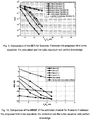
- Figure 4 compares the BER of a turbo equalizer with perfect knowledge of the channel impulse response and the proposed blind turbo equalizer. All the results are shown for the last iteration of the turbo equalizer 5.
- a preferred embodiment of the invention includes utilization of an algorithm that exploits the constraints of a multilevel coded system to blindly estimate the impulse response of a multipath channel.
- the performance of the proposed blind turbo equalizer approaches the performance of the turbo equalizer with perfect knowledge of the impulse response of the channel by only a fraction of dB. Further work on optimizing the codes to each particular level may improve the performance of the blind estimator since it benefits from the quality of the soft feedback of the channel decoder.
- One iteration means one activation of the channel estimator, the equalizer and the decoder.
- 4 iterations are necessary for saturating the system (when no further gain can be achieved with more iterations).
- multi-channel communication systems include multiple-input multiple-output (MIMO) systems, orthogonal frequency division modulation (OFDM) systems, MIMO systems that utilize OFDM, and others.
- MIMO multiple-input multiple-output
- OFDM orthogonal frequency division modulation
- the multi-channel communication systems may also implement code division multiple access (CDMA), time division multiple access (TDMA), frequency division multiple access (FDMA), or some other multiple access techniques. Multiple access techniques can be used to support concurrent communication with a number of terminals.
- CDMA code division multiple access
- TDMA time division multiple access
- FDMA frequency division multiple access
- Multiple access techniques can be used to support concurrent communication with a number of terminals.
- a MIMO system employs multiple transmit antennas and multiple receive antennas for data transmission.
- a MIMO channel formed by the transmit and receive antennas may be decomposed into independent channels.
- Each of the independent channels is also referred to as a spatial sub channel of the MIMO channel and corresponds to a dimension.
- the NT transmit antennas are located at and associated with a single transmitter system, and the NR receive antennas are similarly located at and associated with a single receiver system.
- a MIMO system may also be effectively formed for a multiple access communication system having a base station that concurrently communicates with a number of terminals.
- the base station is equipped with a number of antennas and each terminal may be equipped with one or more antennas.
- An OFDM system effectively partitions the operating frequency band into a number of (NF) frequency sub channels (i.e., frequency bins or sub bands).
- NF frequency sub channels
- a modulation symbol may be transmitted on each of the NF frequency sub channels.
- Each time slot corresponds to a particular time interval that may be dependent on the bandwidth of the frequency sub channel.
- a multi-channel communication system may be operated to transmit data via a number of transmission channels.
- a MIMO system not utilizing OFDM there is typically only one frequency sub channel and each spatial sub channel may be referred to as a transmission channel.
- each spatial sub channel of each frequency sub channel may be referred to as a transmission channel.
- there is only one spatial sub channel for each frequency sub channel and each frequency sub channel may be referred to as a transmission channel.
- the transmission channels in a multi-channel communication system typically experience different link conditions (e.g., due to different fading and multipath effects) and may achieve different signal-to-noise-plus-interference ratios (SNRs). Consequently, the capacity of the transmission channels may be different from channel to channel.
- SNRs signal-to-noise-plus-interference ratios
- this information may be used to distribute the total available transmit power amongst the selected transmission channels and to select the proper coding and modulation scheme.
- the available transmission channels in each group are ranked in order of decreasing received SNR, and the total available transmit power is allocated to and used for the Nu best transmission channels in the group.
- transmission channels having received SNRs that fall below a particular SNR threshold are not selected for use.
- the SNR threshold may be selected to optimize throughput, or some other criteria.
- the total available transmit power for each group is allocated to the selected transmission channels in the group in a defined manner (e.g., uniformly) such that high performance may be achieved.
- Similar processing may be performed if the channel gains (instead of the SNRs) are available at the transmitter system.
- a common coding scheme e.g., a particular Turbo code of a particular code rate
- a common modulation scheme e.g., a particular PSK or QAM constellation
- a simple coding and modulation scheme can be used at the transmitter system for each group of transmission channels, then a single (e.g., convolutional or Turbo) coder and code rate may be used to encode data for all selected transmission channels in the group, and the resultant coded bits may be mapped to modulation symbols using a single (e-g., PSK or QAM) modulation scheme.
- a single (e.g., convolutional or Turbo) coder and code rate may be used to encode data for all selected transmission channels in the group, and the resultant coded bits may be mapped to modulation symbols using a single (e-g., PSK or QAM) modulation scheme.
- the selective channel transmission may be applied individually and independently to groups of transmission channels.
- the selective channel transmission may be independently applied to each group of channels.
- one threshold may be used for all groups, each group may be assigned a separate threshold, or some groups may share the same threshold while other groups may be assigned separate thresholds.
- the same or different transmit power allocation schemes may be used for those groups for which selective channel transmission is applied.
- a different coding and modulation scheme may also be used for each group, which may be selected based on the transmission capacities (e.g., the achieved SNRs) of the selected transmission channels in the group.
- the MIMO construct creates multiple (Ns) transmission channels in the spatial domain and the OFDM construct I create multiple (NF) transmission channels in the frequency domain.
- the transmission channels may then be segregated into a number of groups in various ways.
- the NT groups corresponding to the NT transmit antennas may be associated with Nr respective thresholds, one threshold for each group or transmit antenna.
- the selective channel transmission determines the subset of transmission channels (or frequency sub channels) associated with each transmit antenna having adequate transmission capacities (e.g., received SNRs). This can be achieved, for example, by comparing the received SNR for each frequency sub channel to the threshold for the transmit antenna.
- the total transmit power available for each transmit antenna is then allocated in a defined manner (e.g., uniformly) to the selected frequency sub channels for the transmit antenna.
- the available transmission channels are segregated on a per frequency sub channel basis.
- the selective channel transmission may be applied independently to each of the NF frequency sub channels.
- the spatial sub channels in each group may then be selected for use for data
- the segregation of the available transmission channels into groups permits optimization to be achieved on a per group basis (e.g., per transmit antenna or per frequency sub channel).
- a specific coding and modulation scheme may also be used for all selected transmission channels in each group, which can simplify the processing at both the transmitter and receiver systems.
- one or more transmit antennas may be assigned to each terminal scheduled for data transmission.
- the transmission channels associated with the assigned transmit antennas for each terminal may be placed in a group, the selective channel transmission may be performed on each group of transmission channels, and a single coding and modulation scheme may be used for the data transmission to each terminal.
- Data for each frequency sub channel may be coded and modulated independently based on a coding and modulation scheme selected for that frequency sub channel.
- selective channel transmission is applied to all available transmission channels.
- This implementation of the invention presents an iterative blind channel estimation algorithm that exploits the parity check equations of a channel code. While with conventional pilots prior data knowledge is used to estimate the channel, the idea here is to exploit prior knowledge of the parity check equations of the code. Furthermore, if an asymmetric code is used, the inherent phase ambiguity of blind systems is avoided. Hence, the channel can be blindly estimated to increase the spectral efficiency.
- An algorithm for iterating in a turbo fashion between channel estimator, equalizer and decoder is derived in such a way that the estimates of the channel are considerably refined throughout the iterations.
- the results of the proposed Blind Turbo Equalizer demonstrate that the Mean Square Error (MSE) of the estimated channel reaches the Cramer-Rao Lower Bound (CRLB) in a high SNR regime.
- MSE Mean Square Error
- CRLB Cramer-Rao Lower Bound
- the blind Turbo equalizer reaches the performance of a Turbo Equalizer with perfect knowledge of the channel impulse response.
- Blind estimators according to the state of the art are efficient in terms of spectral efficiency, but their performance can be degraded due to a possible phase ambiguity.
- phase ambiguity can be eliminated using an asymmetric transmitter.
- One way of enforcing this asymmetry is to use an asymmetric channel encoder. Hence, there is no need of the addition of pilot symbols for estimating the channel.
- the method is carried out in a way that before the iterations of the turbo equalizer start a modified version of the channel estimator proposed in [5] is used.
- This implementation of the invention includes the advantage that a derivation of a channel estimator for the subsequent iterations in a turbo way.
- the results of the proposed Blind Turbo Equalizer are very attractive: at high SNR the MSE of the estimated channel reaches the CRLB. In terms of BER, the blind Turbo equalizer reaches the same performance of a Turbo Equalizer with perfect knowledge of the channel impulse response. Hence the proposed Blind Turbo Equalizer becomes an interesting choice due to the increased spectral efficiency when compared to the pilot solution.
- a ( k ) represents the k -th value of a.
- mod (a, 2) means the element-wise modulo two operation of the vector a.
- ⁇ is the convolution operator.
- means the absolute value of a and a the angle of the complex number a .
- l and K are the number of information and coded bits respectively.
- L is the length of the channel. Loglikelihood ratios at equalizer and decoder are denoted by superscripts LE and LD respectively. Subscripts indicate a-priori or extrinsic information, e.g. LE ext.
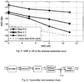
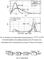
- the transmission model with a transmitter and receiver chain is shown in Figure 6 .
- the coded interleaved bits d ( n ) are mapped by a BPSK modulator, where 0 1 and 1 -1.
- Fig. 7 shows a preferred embodiment of a soft information exchange between blind channel estimator, frequency domain equalizer and MAP decoder.
- Figure 7 depicts the receiver in more detail.
- the received signal, r is used for estimating the channel and for equalization.
- the equalizer computes the extrinsic information, L E ext ( s ), of the transmitted vector s.
- a frequency domain equalizer for a single carrier with cyclic prefix as proposed in [7] is used.
- the extrinsic information L E ext ( s ) at its output is deinterleaved to deliver the a-priori L -values L D a for the decoder (see Figure 7 ).
- the decoder computes the a-posteriori information, L D ( c ) , and the extrinsic information, L E ext ( c ), of the coded bits.
- the interleaved extrinsic information of the coded bits is used as a-priori information of the equalizer and the a-posteriori value is used by the channel estimator.
- the total a-posteriori information of the decoder can be used for the channel estimator since the values of s are uncorrelated with the values of h . Throughout the iterations the quality of the output of the equalizer, the decoder and the channel estimator are refined until the system shows no improvement anymore or the maximum number of iterations is reached.
- the solution for this ambiguity is to use an asymmetric transmission, which can be achieved by using asymmetric modulation [8] [9] or asymmetric codes [5].
- the use of asymmetric constellations decreases the BER of the system compared to the symmetric one.
- the use of asymmetric codes i.e. codes where the negation of each valid codeword is not a valid codeword in the codeword space
- the condition that a code must fulfil to be asymmetric is that the rows of the parity check matrix of the code have an odd numbers of ones. Therefore, a wide range of used channel encoders are asymmetric.
- One example of an asymmetric code is shown in [5]) for a (7, 5) convolutional code.
- constraints of a channel code for estimating the channel are used.
- the properties of (9) and (10) can be used for estimating the l -th tap of the channel.
- the blind channel estimator is modified for receiving feedback from the decoder.
- (12) there is a residual error for the estimated tap due to the fact of using the time average in (11) instead of the true expectation.
- the idea is to use the a-posteriori output of the decoder, L D ( c ), and the channel taps estimated in previous iteration of the Turbo Equalizer, , for cancelling this residue.
- using the estimates of the channel from previous iterations for cancelling the residue in (12) could lead to error propagation, since the estimation of the tap h l would use previous estimates of the tap itself. Therefore, errors having occurred in previous iteration could propagate to the subsequent ones.
- q ⁇ i 1 i ⁇ q P s ⁇ ⁇ m , i + ⁇
- (24) provides a considerable gain of the estimates of the channel throughout the iterations of the turbo equalizer in such a way that it reaches the CRLB for a sufficiently high SNR.
- the encoded bits are mapped by a BPSK modulator and a cyclic prefix of the size of channel length is appended to the frame.
- the algorithm presented in section 3.1 is used for estimating the channel.
- the estimator derived in section 3.2 is used.
- the equalizer used is the one of [7] and according to a preferred embodiment of the invention a LOGMAP decoder [11] is used for a 1/2 rate (7,5) convolutional code. Every iteration of the Turbo Equalizer (channel estimation, equalization and decoding) is performed over one frame.4
- LS Least Squares
- Figure 4 compares the corresponding BER of the proposed blind algorithm and the pilot aided case with the turbo equalizer having perfect knowledge of the impulse response of the channel. For the case of having perfect knowledge of the impulse response of the channel, the necessary number of iterations between equalizer and decoder to reach the saturation is performed.
- the proposed blind turbo equalizer outperforms the pilot aided one and reaches the same performance of the Turbo Equalizer with perfect knowledge of the channel.
- the explanation for this good performance is that the blind channel estimator uses more information (the whole frame) than the pilot aided one for estimating the channel that uses only pilots.
- the quality of the channel estimation becomes proportional to the power of all symbols of the frame, independent whether they are pilots or information.
- the proposed blind channel estimator using priors has a noticeable gain already in the first iteration. Again, for high values of SNR the blind estimator using priors can reach the CRLB since it uses observations of the whole frame. Note that once more the conventional pilot aided estimator is inferior in terms of performance and spectral efficiency. The performance in terms of E b / N 0 versus BER is shown in Figure 6 . This result confirms that the proposed blind channel estimator reaches the performance of the turbo equalizer with perfect knowledge of the channel impulse response. Furthermore, the blind estimator has a gain of roughly 1.3 dB compared to the pilot aided case, which reflects roughly the number of symbols used for estimating the channel.
- a blind channel estimator using the code properties and the LLRs from the decoder is proposed. It is shown that the proposed scheme can significantly increase the performance of the channel estimates and reach the CRLB in high SNR conditions. Therefore, the proposed blind estimator shows a better spectral efficiency and performance compared to the pilot-aided case. Furthermore, since according to a preferred embodiment of the invention a convolutional encoder, which is asymmetric the phase ambiguity is avoided and it is not necessary to use any pilot symbol as in the semi-blind approach. Further implementations of the invention are applying the proposed scheme to higher order modulation and MIMO systems.
- the selected transmission channels may be used to transmit one or more data streams, each of which may be independently coded with the common coding scheme.
- selective channel transmission is applied independently to each transmit antenna.
- the selected transmission channels for each transmit antenna may be used to transmit one or more data streams, each of which may be independently coded with the coding scheme selected for that transmit antenna. If one data stream is independently coded and transmitted on each spatial sub channel, then the successive cancellation receiver processing technique may be used to recover the transmitted data streams.
- the terms s ( k ) and r ( k ) describe the sent and received data at the time of k, h ( 0 ).. . h ( L -1) the so-called channel impulse response of the length of l and n (k) noise (roar) superimposed at the receiver.
- the channel impulse response h not known at the receiver shall be estimated ('blindly') without knowledge of the sent data.
- Preferred embodiment of the invention relates to a method for a regulation of the channel impulse response of a transmission system by evaluation to the reception symbols by the code (exact by the examining equations) based boundary conditions.
- the coefficients of the channel impulse response arise according to this approach from products of the reception symbols formed suitably so that a product results from elements for the channel impulse response.
- the indices ⁇ 1,n ... ⁇ M,n that overlay with medium-unbiased terms ('roaring' data conditionally) give the addresses of the m of reception symbols which could be combined with each other according to an examining equation of the code.
- the inter symbol interference caused by the channel is corrected at the received data stream to initial channel estimation by means of an equalizer (under use of the valued channel impulse response).
- the corrected data symbols are then decoded.
- the estimated values available at the decoder exit for the sent bits can be used for the reconstruction of the send dates or the data-dependent high terms. By this an improved channel estimation is reached.
- the partial results can be combined to a common estimation result.
- the mean squared error (variance) of a blind channel estimator that exploits constraints imposed on valid combinations of code bits (also called 'logic strings') and the respective receive symbols by the parity check equations of a channel code.
- code bits also called 'logic strings'
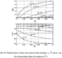
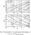
- the dependence of the estimation error on the length of the logic strings, their available number as well as on the channel impulse response is quantified for a finite number of observations, i.e. logic strings that are available within one data block. The result explains, why short logic strings perform significantly better than longer ones. This provides a guideline to choose appropriate codes and allows for given typical channel conditions to select the appropriate code or block length to achieve the desired accuracy of the channel estimate.
- blind estimation methods exploiting certain inherent signal properties have repeatedly been proposed as alternatives to conventional preamble based channel estimation [1], [2].
- HOS higher-order statistics
- Sections 2 and 3 review the concept of logic strings and the technique for blindly estimating a channel with them.
- the main part follows in section 4 that presents the analysis of the estimator and a prediction of its MSE. As usual we summarize with some conclusions.
- the term 'logic string' refers to a constraint imposed on the codeword space in the sense that the code bits obey certain check equations. Such constraints can obviously be expressed in terms of the parity check matrix H (i.e. the null space to the codeword space, such that a certain check equation 'checks' or relates a certain set of code bits).
- the generator matrix or the generator polynomials of the code can be used. To illustrate the concept we take as in Ref. [3] the simple case of a half rate convolutional code with generators [7, 5] 8 .
- Another convenient way to determine the index sets of the logic strings is to write down the generator matrix and then enumerate the non zero indices columnwise to get the index set of the first logic string corresponding to the first rows of a possible parity check matrix H.
- the other logic strings (columns of H T ) are shifts by two.
- each code word c is permuted 1
- the product of 5 receive symbols at the addresses of a logic string it contains the respective transmit symbols weighted with the first channel tap. Because another logic string exists with all addresses decremented by two, it will be picked up as well, when the channel length is larger than 2. This makes the interleaver advantageous.
- a symmetry of the overall response is undesirable.
- any inversion symmetry of the modulation alphabet or the code causes a phase ambiguity of 180°.
- removing symmetry in the modulation format causes an increase in error probability for fixed signal to noise ratio a code C without inversion symmetry does not degrade performance.
- Such an 'asymmetric' code is characterized by the fact that for a given code word c its negation is not within the code space (see [3]):
- the condition for a code to be asymmetric means that at least one logic string with odd length M exists.
- variant I a common delay v ⁇ ⁇ 0, ⁇ L -1 ⁇ is used for addressing the receive symbols corresponding to a logic string. An unconditioned estimate of tap v is obtained. As will become clear from the subsequent analysis of the variance of the estimator, it is advantageous to employ this variant only to estimate the strongest tap and then switch to variant II.
- This variant uses different delays applied to the addresses of a logic string to obtain a conditional estimate of the other taps based on the previously determined estimate of the strongest tap ⁇ v .
- v the strongest tap
- l the arbitrary tap position 2 ; in passing we note, that the scheme can also handle non minimum phase channels were the first tap is not the strongest one.
- the quantity P (M + 1)/2 serves to bipartition the received symbols participating in the evaluation of a logic string after one symbol was split off to select the tap h l.
- This trick allows an unambiguous phase estimate for complex-valued channels, because the phase of h l . depends linearly on ⁇ l which is a higher order moment only in terms of the absolute value, the magnitude of the channel taps.
- ⁇ l consists of L M terms in the noiseless case or (L+1) M terms, if the noise is included, because we multiply M factors of L or L + 1 terms each 3 . It is convenient to address these terms by index M tuples (K 1 ... K M ) which reflect all possible combinations of delays (terms in one factor) in the product of all M factors. Each index K m ranges from 0 to L - 1 (or L, if noise is included).
- the desired h ⁇ l h v M ⁇ 1 term is a deterministic quantity plus a sum of products of two factors u t and v t that depend on the index M-tuples (K 1 ... K M )
- u t K 1 ... K M
- u t K 1 ... K M
- the frequency of occurrence of the same combination of channel taps in the L M - 1 terms is given by a polynomial coefficient.
- v t (K 1 ... K M ) is a random variable with binomial distribution, because for BPSK symbols the product s ( ⁇ m,n + v - ⁇ m ) is either plus or minus one.
- V t of the terms v t (K 1 ... K M ) belonging to a given index M tuple when evaluating the arithmetic mean within one block over the available N logic strings corresponds to the sum over binomially distributed random variables v t ( n ) ⁇ ⁇ 1 ⁇ :
- v t n ⁇ v t n ⁇ 1 ⁇ ⁇ v t n ⁇ ⁇ 1 .
- ⁇ ( ⁇ ) and 1 F 1 (a,b,c,) denote the Gamma and (confluent) hypergeometric functions, respectively [5].
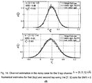
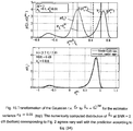
- Fig. 15 Schematically this is presented in Fig. 15 (top).
- the variance of ⁇ l is ill-defined due to the possibility of h ⁇ v M ⁇ 1 becoming zero, because the Gaussian distribution it follows, extends to ⁇ .
- the best one can say is that for fixing the random variable ⁇ v at a given value (as an instantaneous estimate) the resulting distribution p ( ⁇ l ) is also Gaussian and that the variance of ⁇ l is scaled accordingly.
- the estimator analysis for real channels can be extended to complex channels, noting that the products of BPSK symbols remain binomially distributed and the weights coming from products of powers of the channel taps become complex.
- the power of the data dependent noise terms will be the product of the number of evaluated logic strings N and the powers of the taps of the channel impulse response and we end up again at Eq. (40) or with additional complex additive white Gaussian noise at Eq. (41).
- the channel tap distribution now is also two-dimensional but can be approximated with Eq. (44), when projecting the tap estimate onto the axis defined by the argument of the estimated tap.
- the complex estimator performs slightly better than in the real case for the same SNR, because part of the noise is orthogonal to the direction of the tap and does not affect the estimated amplitude.
- the MSE for a blind higher order channel estimator is based on the parity check constraints of a channel code.
- phase correct estimation is also feasible.
- a transmission model is used.
- an algorithm to blindly estimate the channel exploiting channel coding is used.
- the performance of the algorithm is evaluated on the basis of simulation results in
- the transmission is characterized by the discrete time channel impulse response (CIR) h k of order H including pulse shaping and receive filter.
- CIR discrete time channel impulse response
- logic strings 1 which is defined as follows: Definition 1: A set of encoded bits is called logic string, when the XOR-conjunction of its elements always gives a zero for each arbitrary original data sequence.
- N logic strings of length M according to an encoding scheme.
- N the set of cardinality N containing all time indices corresponding to logic strings of this type.
- ⁇ 1 , n ⁇ 2 , n ⁇ ⁇ M , n ⁇ be the time indices corresponding to the n-th valid logic string.
- phase correct channel estimation can be attained, if the encoding scheme is non-symmetric, where the term "asymmetric" is defined as follows: Definition 2: A code is called asymmetric if the negation of each valid code word is not a valid code word, i.e.
- the concept of logic strings is closely related to the representation of the parity check matrix and the null space corresponding to the code space, respectively. An important difference is that the length of a set of logic strings is fixed, whereas e.g. the number of ones in each column vector of a syndrome matrix may vary.
- the estimate ⁇ l consists of the true channel coefficient ⁇ l , which is weighted by a real positive factor
- the expectation in (15) is not available. Thus, it must be approximated by averaging over N logic strings.
- the encoder usually shows a periodical structure. It can be shown that in these case also the logic strings may have a periodical structure. Due to the fact that the channel causes a weighted superposition of encoded data, it is not unlikely that beside the logic string of interest a parasitic logic string is caught. In order to avoid this effect interleaving the encoded data is mandatory for our approach.
- e should contain at least one nonzero entry at index H ⁇ k 0 ⁇ L in order to ensure a nonzero entry of the joint impulse response w at index fc.
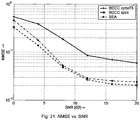
- NMSE normalized mean squared error
- SEA super exponential algorithm [2] is used, which is a typical HOS-based method.
- SEA will also consist of several iterations, where jointly a linear filter is adapted and the channel is estimated.
- Fig. 21 shows the NMSE performance versus signal to noise ratio (SNR).
- SNR signal to noise ratio
- an iterative algorithm is used, which blindly identifies the channel exploiting the statistical dependencies of the transmitted signal caused by channel coding.
- the algorithm jointly updates channel estimates and adapts a linear equalizer.
- the algorithm delivers phase correct estimates.
- a transmitter is composed by a multilevel encoder as it is for example presented in Figure 1 .
- a further object of the invention is a receiver which is composed by a turbo equalizer.
- the turbo equalizer is composed by a channel estimator, an equalizer and a decoder.
- the invention includes an algorithm used especially in the equalizer and/or in the decoder.
- This algorithm is for example a soft input output (equalizing/decoding) algorithm.
- a preferred embodiment of the invention includes an iterative procedure. At the first iteration (when no a-priori values from the decoder are available) the channel is estimated using according a suitable mechanism, especially using eq. 14 and 17. The first level can be used for channel estimation. Another alternative is to estimate the channel based in all levels.
- the invention is not limited to a special combination of estimates of the different levels.
- the invention is independent from the number of iterations between channel estimator, equalizer and decoder.
Landscapes
- Engineering & Computer Science (AREA)
- Power Engineering (AREA)
- Computer Networks & Wireless Communication (AREA)
- Signal Processing (AREA)
- Physics & Mathematics (AREA)
- Probability & Statistics with Applications (AREA)
- Cable Transmission Systems, Equalization Of Radio And Reduction Of Echo (AREA)
- Error Detection And Correction (AREA)
- Radio Transmission System (AREA)
- Testing, Inspecting, Measuring Of Stereoscopic Televisions And Televisions (AREA)
- Detection And Prevention Of Errors In Transmission (AREA)
Claims (5)
- Verfahren zum Auswählen von Übertragungskanälen in einem mehrkanaligen Kommunikationssystem für die Verwendung zur Datenübertragung:wobei Daten s(k) zu einem Zeitpunkt k gesendet werden,wobei die Daten s(k) empfangen werden, wobei r(k) Daten bezeichnet, die zum Zeitpunkt k empfangen werden, und wobei ein Vergleich zwischen gesendeten Daten und empfangenen Daten nach der folgenden Formel erfolgt:
 wobei h(0)... h(L-1) eine Kanalimpulsantwort mit einer Länge L bezeichnet und n(k) Rauschsignale am Empfänger bezeichnet,dadurch gekennzeichnet, dassein Kanalblindschätzer so modifiziert wird, dass er eine Rückmeldung von einem Dekodierer mit einem Restfehler für einen geschätzten Abgriff aufgrund der Verwendung eines Zeitmittelwerts anstelle eines wahren Erwartungswerts empfängt, wobei eine A-posteriori-Ausgabe des Dekodierers LD(c), bei dem c ein Vektor von kodierten Bits ist, und Kanalabgriffe, die in einer vorhergehenden Iteration eines Turbo-Equalizers uh geschätzt worden sind, zum Löschen des Rests verwendet werden, wobei ein Moment P-ter Ordnung, der zum Schätzen eines l-ten Abgriffs des Kanals berechnet wird und bei dem P und I natürliche Zahlen sind, auf eine solche Weise geändert wird, dass der für den Zeitmittelwert erzeugte Restfehler den l-ten Abgriff selbst nicht enthält und dass eine modifizierte Version des Moments P-ter Ordnung, die in dem Kanalblindschätzer verwendet wird, durch folgende Formel gegeben ist:
 wobei M eine Zahl logischer Strings, d.h. eine Menge kodierter Bits, ist, wobei die exklusive ODER-Funktion ihrer Elemente für jede zufällige ursprüngliche Datenfolge immer Null ist, π ein Index-Operator ist und ŝ der Vektor der geschätzten Symbole, die von dem Dekodierer berechnet worden sind, ist und durch die folgende Formel gegeben ist:
 und der Restfehler u aufgrund eines Näherungserwartungswerts über nicht logische Stringkomponenten nach der folgenden Formel berechnet wird:
 wobei die Summe in der Formel alle Abgriffe des Kanals außer dem gewünschten l-ten Abgriff beinhaltet und die Werte von s nicht mit den Werten von h korreliert sind.
 - Verfahren nach Anspruch 1, wobei die geschätzten Abgriffe aus der vorhergehenden Iteration des Turbo-Equalizers ȟ und die geschätzten Symbole ŝ und der geschätzte Restfehler nach der folgenden Formel berechnet werden:

- Verfahren nach Anspruch 2, wobei der Restfehler eines nicht wahren Erwartungswerts geschätzt und zur Verbesserung der Qualität des geschätzten Abgriffs nach der folgenden Formel verwendet wird:


- Verfahren nach Anspruch 3, wobei der Faktor


- Sendeempfänger, der einen Sender und einen Empfänger zur Einzelträgerkommunikation umfasst und über Mehrwegkanäle arbeitet, wobei der Sender aus einem mehrstufigen Kodierer besteht, wobei der Empfänger aus einem Blind-Turbo-Equalizer besteht, der geeignet ist, Übertragungskanäle in einem mehrkanaligen Kommunikationssystem für die Verwendung zur Datenübertragung auszuwählen:wobei Daten s(k) zu einem Zeitpunkt k gesendet werden,wobei die Daten s(k) empfangen werden, wobei r(k) Daten bezeichnet, die zum Zeitpunkt k empfangen werden, und wobei der Blind-Turbo-Equalizer geeignet ist, gesendete Daten und empfangene Daten nach der folgenden Formel zu vergleichen:
 wobei h(0)... h(L-1) eine Kanalimpulsantwort mit einer Länge L bezeichnet und n(k) Rauschsignale am Empfänger bezeichnet,dadurch gekennzeichnet, dassder Blind-Turbo-Equalizer geeignet ist, den Kanalblindschätzer so zu modifizieren, dass er eine Rückmeldung von einem Dekodierer mit einem Restfehler für einen geschätzten Abgriff aufgrund der Verwendung eines Zeitmittelwerts anstelle eines wahren Erwartungswerts empfängt, wobei eine A-posteriori-Ausgabe des Dekodierers LD(c), bei dem c ein Vektor von kodierten Bits ist, und Kanalabgriffe, die in einer vorhergehenden Iteration eines Turbo-Equalizers uh geschätzt worden sind, zum Löschen des Rests verwendet werden, wobei ein Moment P-ter Ordnung, der zum Schätzen eines l-ten Abgriffs des Kanals berechnet wird und bei dem P und I natürliche Zahlen sind, auf eine solche Weise geändert wird, dass der für den Zeitmittelwert erzeugte Restfehler den l-ten Abgriff selbst nicht enthält und dass eine modifizierte Version des Moments P-ter Ordnung, die in dem Kanalblindschätzer verwendet wird, durch folgende Formel gegeben ist:
 wobei M eine Zahl logischer Strings, d.h. eine Menge kodierter Bits, ist, wobei die exklusive ODER-Funktion ihrer Elemente für jede zufällige ursprüngliche Datenfolge immer Null ist, π ein Index-Operator ist und ŝ der Vektor der geschätzten Symbole, die von dem Dekodierer berechnet worden sind, ist und durch die folgende Formel gegeben ist:
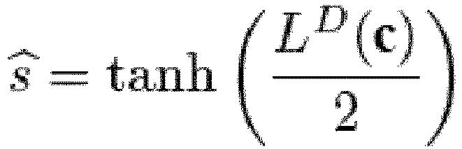 und der Restfehler u aufgrund eines Näherungserwartungswerts über nicht logische Stringkomponenten nach der folgenden Formel berechnet wird:
 wobei die Summe in der Formel alle Abgriffe des Kanals außer dem gewünschten l-ten Abgriff beinhaltet und die Werte von s nicht mit den Werten von h korreliert sind.
Priority Applications (4)
| Application Number | Priority Date | Filing Date | Title |
|---|---|---|---|
| EP08000707.3A EP2071786B1 (de) | 2007-12-14 | 2008-01-15 | Verfahren und Sende-Empfänger zur Datenkommunikation |
| EP08860858.3A EP2223483B1 (de) | 2007-12-14 | 2008-12-12 | Blind-turbo-kanalschätzung |
| US12/808,171 US20100296556A1 (en) | 2007-12-14 | 2008-12-12 | Method and transceiver using blind channel estimation |
| PCT/EP2008/010594 WO2009077135A2 (en) | 2007-12-14 | 2008-12-12 | Blind turbo channel estimation |
Applications Claiming Priority (2)
| Application Number | Priority Date | Filing Date | Title |
|---|---|---|---|
| EP07024345 | 2007-12-14 | ||
| EP08000707.3A EP2071786B1 (de) | 2007-12-14 | 2008-01-15 | Verfahren und Sende-Empfänger zur Datenkommunikation |
Publications (3)
| Publication Number | Publication Date |
|---|---|
| EP2071786A2 EP2071786A2 (de) | 2009-06-17 |
| EP2071786A3 EP2071786A3 (de) | 2011-05-11 |
| EP2071786B1 true EP2071786B1 (de) | 2020-12-23 |
Family
ID=39218006
Family Applications (3)
| Application Number | Title | Priority Date | Filing Date |
|---|---|---|---|
| EP08000707.3A Active EP2071786B1 (de) | 2007-12-14 | 2008-01-15 | Verfahren und Sende-Empfänger zur Datenkommunikation |
| EP08000644.8A Active EP2071785B1 (de) | 2007-12-14 | 2008-01-15 | Blinde Kanalschätzung |
| EP08860858.3A Active EP2223483B1 (de) | 2007-12-14 | 2008-12-12 | Blind-turbo-kanalschätzung |
Family Applications After (2)
| Application Number | Title | Priority Date | Filing Date |
|---|---|---|---|
| EP08000644.8A Active EP2071785B1 (de) | 2007-12-14 | 2008-01-15 | Blinde Kanalschätzung |
| EP08860858.3A Active EP2223483B1 (de) | 2007-12-14 | 2008-12-12 | Blind-turbo-kanalschätzung |
Country Status (3)
| Country | Link |
|---|---|
| US (1) | US20100296556A1 (de) |
| EP (3) | EP2071786B1 (de) |
| WO (1) | WO2009077135A2 (de) |
Families Citing this family (82)
| Publication number | Priority date | Publication date | Assignee | Title |
|---|---|---|---|---|
| US9071344B2 (en) | 2005-08-22 | 2015-06-30 | Qualcomm Incorporated | Reverse link interference cancellation |
| US8611305B2 (en) | 2005-08-22 | 2013-12-17 | Qualcomm Incorporated | Interference cancellation for wireless communications |
| US20100046660A1 (en) | 2008-05-13 | 2010-02-25 | Qualcomm Incorporated | Interference cancellation under non-stationary conditions |
| US8995417B2 (en) | 2008-06-09 | 2015-03-31 | Qualcomm Incorporated | Increasing capacity in wireless communication |
| US9277487B2 (en) * | 2008-08-01 | 2016-03-01 | Qualcomm Incorporated | Cell detection with interference cancellation |
| US9237515B2 (en) | 2008-08-01 | 2016-01-12 | Qualcomm Incorporated | Successive detection and cancellation for cell pilot detection |
| US8509293B2 (en) * | 2008-08-19 | 2013-08-13 | Qualcomm Incorporated | Semi-coherent timing propagation for GERAN multislot configurations |
| US8503591B2 (en) * | 2008-08-19 | 2013-08-06 | Qualcomm Incorporated | Enhanced geran receiver using channel input beamforming |
| US9160577B2 (en) | 2009-04-30 | 2015-10-13 | Qualcomm Incorporated | Hybrid SAIC receiver |
| US8787509B2 (en) | 2009-06-04 | 2014-07-22 | Qualcomm Incorporated | Iterative interference cancellation receiver |
| US8831149B2 (en) | 2009-09-03 | 2014-09-09 | Qualcomm Incorporated | Symbol estimation methods and apparatuses |
| US8619928B2 (en) * | 2009-09-03 | 2013-12-31 | Qualcomm Incorporated | Multi-stage interference suppression |
| KR101376676B1 (ko) | 2009-11-27 | 2014-03-20 | 퀄컴 인코포레이티드 | 무선 통신들에서의 용량 증가 |
| ES2708959T3 (es) | 2009-11-27 | 2019-04-12 | Qualcomm Inc | Mayor capacidad en comunicaciones inalámbricas |
| US9288089B2 (en) | 2010-04-30 | 2016-03-15 | Ecole Polytechnique Federale De Lausanne (Epfl) | Orthogonal differential vector signaling |
| US9564994B2 (en) | 2010-05-20 | 2017-02-07 | Kandou Labs, S.A. | Fault tolerant chip-to-chip communication with advanced voltage |
| US9251873B1 (en) | 2010-05-20 | 2016-02-02 | Kandou Labs, S.A. | Methods and systems for pin-efficient memory controller interface using vector signaling codes for chip-to-chip communications |
| US9985634B2 (en) | 2010-05-20 | 2018-05-29 | Kandou Labs, S.A. | Data-driven voltage regulator |
| US9077386B1 (en) | 2010-05-20 | 2015-07-07 | Kandou Labs, S.A. | Methods and systems for selection of unions of vector signaling codes for power and pin efficient chip-to-chip communication |
| US8593305B1 (en) | 2011-07-05 | 2013-11-26 | Kandou Labs, S.A. | Efficient processing and detection of balanced codes |
| US9450744B2 (en) | 2010-05-20 | 2016-09-20 | Kandou Lab, S.A. | Control loop management and vector signaling code communications links |
| US9106220B2 (en) | 2010-05-20 | 2015-08-11 | Kandou Labs, S.A. | Methods and systems for high bandwidth chip-to-chip communications interface |
| US9596109B2 (en) | 2010-05-20 | 2017-03-14 | Kandou Labs, S.A. | Methods and systems for high bandwidth communications interface |
| US9288082B1 (en) | 2010-05-20 | 2016-03-15 | Kandou Labs, S.A. | Circuits for efficient detection of vector signaling codes for chip-to-chip communication using sums of differences |
| US9246713B2 (en) | 2010-05-20 | 2016-01-26 | Kandou Labs, S.A. | Vector signaling with reduced receiver complexity |
| US9479369B1 (en) | 2010-05-20 | 2016-10-25 | Kandou Labs, S.A. | Vector signaling codes with high pin-efficiency for chip-to-chip communication and storage |
| US9667379B2 (en) | 2010-06-04 | 2017-05-30 | Ecole Polytechnique Federale De Lausanne (Epfl) | Error control coding for orthogonal differential vector signaling |
| US9275720B2 (en) | 2010-12-30 | 2016-03-01 | Kandou Labs, S.A. | Differential vector storage for dynamic random access memory |
| US8949693B2 (en) * | 2011-03-04 | 2015-02-03 | Hewlett-Packard Development Company, L.P. | Antipodal-mapping-based encoders and decoders |
| US20130170842A1 (en) * | 2012-01-04 | 2013-07-04 | Toshiaki Koike-Akino | Method and System for Equalization and Decoding Received Signals Based on High-Order Statistics in Optical Communication Networks |
| US9268683B1 (en) | 2012-05-14 | 2016-02-23 | Kandou Labs, S.A. | Storage method and apparatus for random access memory using codeword storage |
| EP2706684B1 (de) * | 2012-09-10 | 2018-11-07 | MStar Semiconductor, Inc | Vorrichtung für MIMO-Kanalleistungsvorhersage |
| CN104995612B (zh) | 2013-01-17 | 2020-01-03 | 康杜实验室公司 | 低同步开关噪声芯片间通信方法和系统 |
| WO2014172377A1 (en) | 2013-04-16 | 2014-10-23 | Kandou Labs, S.A. | Methods and systems for high bandwidth communications interface |
| CN105393512B (zh) | 2013-06-25 | 2019-06-28 | 康杜实验室公司 | 具有低接收器复杂度的向量信令 |
| WO2015064794A1 (en) * | 2013-11-01 | 2015-05-07 | Lg Electronics Inc. | Method and apparatus for receiving signal in wireless communication system |
| US9106465B2 (en) | 2013-11-22 | 2015-08-11 | Kandou Labs, S.A. | Multiwire linear equalizer for vector signaling code receiver |
| US9806761B1 (en) | 2014-01-31 | 2017-10-31 | Kandou Labs, S.A. | Methods and systems for reduction of nearest-neighbor crosstalk |
| CN105993151B (zh) | 2014-02-02 | 2019-06-21 | 康杜实验室公司 | 低isi比低功率芯片间通信方法和装置 |
| EP3672176B1 (de) | 2014-02-28 | 2022-05-11 | Kandou Labs, S.A. | Vektorsignalisierungskodes mit eingebettetem takt |
| US11240076B2 (en) | 2014-05-13 | 2022-02-01 | Kandou Labs, S.A. | Vector signaling code with improved noise margin |
| US9509437B2 (en) | 2014-05-13 | 2016-11-29 | Kandou Labs, S.A. | Vector signaling code with improved noise margin |
| US9148087B1 (en) | 2014-05-16 | 2015-09-29 | Kandou Labs, S.A. | Symmetric is linear equalization circuit with increased gain |
| US9852806B2 (en) | 2014-06-20 | 2017-12-26 | Kandou Labs, S.A. | System for generating a test pattern to detect and isolate stuck faults for an interface using transition coding |
| US9112550B1 (en) | 2014-06-25 | 2015-08-18 | Kandou Labs, SA | Multilevel driver for high speed chip-to-chip communications |
| EP3138253A4 (de) * | 2014-07-10 | 2018-01-10 | Kandou Labs S.A. | Vektorsignalisierungscodierung mit erhöhten signal-rausch-eigenschaften |
| US9432082B2 (en) | 2014-07-17 | 2016-08-30 | Kandou Labs, S.A. | Bus reversable orthogonal differential vector signaling codes |
| KR102243423B1 (ko) | 2014-07-21 | 2021-04-22 | 칸도우 랩스 에스에이 | 다분기 데이터 전송 |
| US9461862B2 (en) | 2014-08-01 | 2016-10-04 | Kandou Labs, S.A. | Orthogonal differential vector signaling codes with embedded clock |
| US9674014B2 (en) | 2014-10-22 | 2017-06-06 | Kandou Labs, S.A. | Method and apparatus for high speed chip-to-chip communications |
| KR101978470B1 (ko) | 2015-06-26 | 2019-05-14 | 칸도우 랩스 에스에이 | 고속 통신 시스템 |
| US9557760B1 (en) | 2015-10-28 | 2017-01-31 | Kandou Labs, S.A. | Enhanced phase interpolation circuit |
| US9577815B1 (en) | 2015-10-29 | 2017-02-21 | Kandou Labs, S.A. | Clock data alignment system for vector signaling code communications link |
| US10055372B2 (en) | 2015-11-25 | 2018-08-21 | Kandou Labs, S.A. | Orthogonal differential vector signaling codes with embedded clock |
| WO2017132292A1 (en) | 2016-01-25 | 2017-08-03 | Kandou Labs, S.A. | Voltage sampler driver with enhanced high-frequency gain |
| CN115051705B (zh) | 2016-04-22 | 2025-05-09 | 康杜实验室公司 | 高性能锁相环 |
| US10153591B2 (en) | 2016-04-28 | 2018-12-11 | Kandou Labs, S.A. | Skew-resistant multi-wire channel |
| WO2017189931A1 (en) | 2016-04-28 | 2017-11-02 | Kandou Labs, S.A. | Vector signaling codes for densely-routed wire groups |
| EP3449606A4 (de) | 2016-04-28 | 2019-11-27 | Kandou Labs S.A. | Mehrstufiger treiber mit geringem stromverbrauch |
| US9906358B1 (en) | 2016-08-31 | 2018-02-27 | Kandou Labs, S.A. | Lock detector for phase lock loop |
| US10411922B2 (en) | 2016-09-16 | 2019-09-10 | Kandou Labs, S.A. | Data-driven phase detector element for phase locked loops |
| US10200188B2 (en) | 2016-10-21 | 2019-02-05 | Kandou Labs, S.A. | Quadrature and duty cycle error correction in matrix phase lock loop |
| US10200218B2 (en) | 2016-10-24 | 2019-02-05 | Kandou Labs, S.A. | Multi-stage sampler with increased gain |
| US10372665B2 (en) | 2016-10-24 | 2019-08-06 | Kandou Labs, S.A. | Multiphase data receiver with distributed DFE |
| EP3610576B1 (de) | 2017-04-14 | 2022-12-28 | Kandou Labs, S.A. | Pipeline-vorwärtsfehlerkorrektur für vektorsignalisierungscodekanal |
| DE112018002643T5 (de) | 2017-05-22 | 2020-05-07 | Invention Mine, Llc | Multimodale datengetriebene taktwiederherstellungsschaltung |
| US10116468B1 (en) | 2017-06-28 | 2018-10-30 | Kandou Labs, S.A. | Low power chip-to-chip bidirectional communications |
| US10686583B2 (en) | 2017-07-04 | 2020-06-16 | Kandou Labs, S.A. | Method for measuring and correcting multi-wire skew |
| US10693587B2 (en) | 2017-07-10 | 2020-06-23 | Kandou Labs, S.A. | Multi-wire permuted forward error correction |
| US10203226B1 (en) | 2017-08-11 | 2019-02-12 | Kandou Labs, S.A. | Phase interpolation circuit |
| US10326623B1 (en) | 2017-12-08 | 2019-06-18 | Kandou Labs, S.A. | Methods and systems for providing multi-stage distributed decision feedback equalization |
| US10467177B2 (en) | 2017-12-08 | 2019-11-05 | Kandou Labs, S.A. | High speed memory interface |
| CN111684772B (zh) | 2017-12-28 | 2023-06-16 | 康杜实验室公司 | 同步切换多输入解调比较器 |
| CN109995684B (zh) * | 2017-12-29 | 2021-11-16 | 深圳市天凯利信息科技有限公司 | 一种半盲信道估计方法和装置 |
| US10554380B2 (en) | 2018-01-26 | 2020-02-04 | Kandou Labs, S.A. | Dynamically weighted exclusive or gate having weighted output segments for phase detection and phase interpolation |
| CN108933606B (zh) * | 2018-08-15 | 2021-07-27 | 电子科技大学 | 一种容误码的系统卷积码盲识别方法 |
| CN109831396B (zh) * | 2019-03-07 | 2021-05-18 | 西安电子科技大学 | 短突发mimo通信系统的半盲信道估计方法 |
| CN113676225B (zh) * | 2020-05-15 | 2022-10-04 | 华为技术有限公司 | 一种大规模mimo预编码传输方法与装置 |
| US11108599B1 (en) * | 2020-07-22 | 2021-08-31 | Huawei Technologies Co. Ltd. | Method and apparatus for frequency domain equalization with low complexity and loop delay |
| CN114244670B (zh) * | 2021-12-08 | 2023-04-18 | 北京理工大学 | 一种基于信道编码辅助的盲信道估计方法及系统 |
| WO2024049482A1 (en) | 2022-08-30 | 2024-03-07 | Kandou Labs SA | Pre-scaler for orthogonal differential vector signalling |
| WO2025188375A1 (en) * | 2023-10-26 | 2025-09-12 | The Regents Of The University Of California | Active sensing and inference methods and systems for millimeter wave applications |
Family Cites Families (4)
| Publication number | Priority date | Publication date | Assignee | Title |
|---|---|---|---|---|
| US20030125040A1 (en) * | 2001-11-06 | 2003-07-03 | Walton Jay R. | Multiple-access multiple-input multiple-output (MIMO) communication system |
| US7139336B2 (en) * | 2002-04-05 | 2006-11-21 | Nokia Corporation | Method and system for channel estimation using iterative estimation and detection |
| US8265209B2 (en) * | 2005-10-28 | 2012-09-11 | Qualcomm Incorporated | Method and apparatus for channel and noise estimation |
| KR20080085598A (ko) * | 2007-03-20 | 2008-09-24 | 엘지전자 주식회사 | 제어정보 검출을 위한 데이터 전송 방법 |
-
2008
- 2008-01-15 EP EP08000707.3A patent/EP2071786B1/de active Active
- 2008-01-15 EP EP08000644.8A patent/EP2071785B1/de active Active
- 2008-12-12 EP EP08860858.3A patent/EP2223483B1/de active Active
- 2008-12-12 WO PCT/EP2008/010594 patent/WO2009077135A2/en not_active Ceased
- 2008-12-12 US US12/808,171 patent/US20100296556A1/en not_active Abandoned
Non-Patent Citations (1)
| Title |
|---|
| None * |
Also Published As
| Publication number | Publication date |
|---|---|
| EP2071785A3 (de) | 2011-05-25 |
| EP2223483B1 (de) | 2018-02-07 |
| EP2223483A2 (de) | 2010-09-01 |
| EP2071785B1 (de) | 2021-05-05 |
| EP2071786A3 (de) | 2011-05-11 |
| US20100296556A1 (en) | 2010-11-25 |
| EP2071785A2 (de) | 2009-06-17 |
| WO2009077135A3 (en) | 2009-09-03 |
| EP2071786A2 (de) | 2009-06-17 |
| WO2009077135A2 (en) | 2009-06-25 |
Similar Documents
| Publication | Publication Date | Title |
|---|---|---|
| EP2071785B1 (de) | Blinde Kanalschätzung | |
| CN100438395C (zh) | 均衡装置和方法 | |
| US7567635B2 (en) | Single antenna interference suppression in a wireless receiver | |
| CN104980201B (zh) | 波束成形的方法和波束成形设备 | |
| US20070127608A1 (en) | Blind interference mitigation in a digital receiver | |
| US7065371B1 (en) | Channel order selection and channel estimation in wireless communication system | |
| JP2008507218A (ja) | Ofdmaのための専用パイロットトーンを用いた反復的なチャネルおよび干渉推定 | |
| CN101005299B (zh) | 信号处理的方法和系统 | |
| Gerstacker et al. | Trellis-based receivers for SC-FDMA transmission over MIMO ISI channels | |
| Haselmayr et al. | Iterative detection for unique word OFDM | |
| JP2008535403A (ja) | 等化制御に関する方法及び装置 | |
| Cheema et al. | Iterative ICI cancellation in MIMO OFDM WiMAX system with LDPC channel coding | |
| Satana et al. | A Reduced Complexity Generic NOMA MAP Receiver for Wideband MIMO Channels | |
| Oyerinde et al. | Iterative OFDM Receiver with Decision Directed Channel Estimation | |
| Lehmann et al. | Single-antenna interference cancellation for complex-valued signal constellations with applications to GSM/EDGE | |
| dos Santos et al. | Blind turbo multipath channel estimation of PAM signals exploiting multilevel codes | |
| Shinbox et al. | A two symbols ISDIC turbo equalizer with high performance and low complexity | |
| Adachi et al. | Iterative modified QRM-MLD based on CRC check for OFDM MIMO multiplexing | |
| dos Santos et al. | Iterative blind receiver exploiting channel code constraints for 60 GHz UWB channels | |
| Chen | Iterative Detection for Overloaded Multiuser MIMO OFDM Systems | |
| dos Santos et al. | Blind Turbo Channel Estimation Exploiting Parity Check Equations | |
| Shinbox et al. | High performance and low complexity two symbols ISDIC turbo equalizer | |
| Li | Space-time encoding and decoding for MIMO systems and cooperative communication systems | |
| Großmann | Transmission strategies for broadband wireless systems with MMSE turbo equalization | |
| Beinschob et al. | Adaptive MIMO Channel Estimation Utilizing Modern Channel Codes |
Legal Events
| Date | Code | Title | Description |
|---|---|---|---|
| PUAI | Public reference made under article 153(3) epc to a published international application that has entered the european phase |
Free format text: ORIGINAL CODE: 0009012 |
|
| AK | Designated contracting states |
Kind code of ref document: A2 Designated state(s): AT BE BG CH CY CZ DE DK EE ES FI FR GB GR HR HU IE IS IT LI LT LU LV MC MT NL NO PL PT RO SE SI SK TR |
|
| AX | Request for extension of the european patent |
Extension state: AL BA MK RS |
|
| PUAL | Search report despatched |
Free format text: ORIGINAL CODE: 0009013 |
|
| AK | Designated contracting states |
Kind code of ref document: A3 Designated state(s): AT BE BG CH CY CZ DE DK EE ES FI FR GB GR HR HU IE IS IT LI LT LU LV MC MT NL NO PL PT RO SE SI SK TR |
|
| AX | Request for extension of the european patent |
Extension state: AL BA MK RS |
|
| 17P | Request for examination filed |
Effective date: 20111109 |
|
| 17Q | First examination report despatched |
Effective date: 20111220 |
|
| AKX | Designation fees paid |
Designated state(s): AT BE BG CH CY CZ DE DK EE ES FI FR GB GR HR HU IE IS IT LI LT LU LV MC MT NL NO PL PT RO SE SI SK TR |
|
| STAA | Information on the status of an ep patent application or granted ep patent |
Free format text: STATUS: EXAMINATION IS IN PROGRESS |
|
| REG | Reference to a national code |
Ref country code: DE Ref legal event code: R079 Ref document number: 602008063591 Country of ref document: DE Free format text: PREVIOUS MAIN CLASS: H04L0025030000 Ipc: H04L0025020000 |
|
| RIC1 | Information provided on ipc code assigned before grant |
Ipc: H04L 25/02 20060101AFI20180314BHEP Ipc: H04L 25/03 20060101ALI20180314BHEP |
|
| GRAP | Despatch of communication of intention to grant a patent |
Free format text: ORIGINAL CODE: EPIDOSNIGR1 |
|
| STAA | Information on the status of an ep patent application or granted ep patent |
Free format text: STATUS: GRANT OF PATENT IS INTENDED |
|
| INTG | Intention to grant announced |
Effective date: 20200703 |
|
| GRAS | Grant fee paid |
Free format text: ORIGINAL CODE: EPIDOSNIGR3 |
|
| GRAA | (expected) grant |
Free format text: ORIGINAL CODE: 0009210 |
|
| STAA | Information on the status of an ep patent application or granted ep patent |
Free format text: STATUS: THE PATENT HAS BEEN GRANTED |
|
| AK | Designated contracting states |
Kind code of ref document: B1 Designated state(s): AT BE BG CH CY CZ DE DK EE ES FI FR GB GR HR HU IE IS IT LI LT LU LV MC MT NL NO PL PT RO SE SI SK TR |
|
| REG | Reference to a national code |
Ref country code: GB Ref legal event code: FG4D |
|
| REG | Reference to a national code |
Ref country code: DE Ref legal event code: R096 Ref document number: 602008063591 Country of ref document: DE |
|
| REG | Reference to a national code |
Ref country code: AT Ref legal event code: REF Ref document number: 1348791 Country of ref document: AT Kind code of ref document: T Effective date: 20210115 |
|
| REG | Reference to a national code |
Ref country code: IE Ref legal event code: FG4D |
|
| PG25 | Lapsed in a contracting state [announced via postgrant information from national office to epo] |
Ref country code: GR Free format text: LAPSE BECAUSE OF FAILURE TO SUBMIT A TRANSLATION OF THE DESCRIPTION OR TO PAY THE FEE WITHIN THE PRESCRIBED TIME-LIMIT Effective date: 20210324 Ref country code: FI Free format text: LAPSE BECAUSE OF FAILURE TO SUBMIT A TRANSLATION OF THE DESCRIPTION OR TO PAY THE FEE WITHIN THE PRESCRIBED TIME-LIMIT Effective date: 20201223 Ref country code: NO Free format text: LAPSE BECAUSE OF FAILURE TO SUBMIT A TRANSLATION OF THE DESCRIPTION OR TO PAY THE FEE WITHIN THE PRESCRIBED TIME-LIMIT Effective date: 20210323 |
|
| REG | Reference to a national code |
Ref country code: AT Ref legal event code: MK05 Ref document number: 1348791 Country of ref document: AT Kind code of ref document: T Effective date: 20201223 |
|
| REG | Reference to a national code |
Ref country code: NL Ref legal event code: MP Effective date: 20201223 |
|
| PG25 | Lapsed in a contracting state [announced via postgrant information from national office to epo] |
Ref country code: LV Free format text: LAPSE BECAUSE OF FAILURE TO SUBMIT A TRANSLATION OF THE DESCRIPTION OR TO PAY THE FEE WITHIN THE PRESCRIBED TIME-LIMIT Effective date: 20201223 Ref country code: SE Free format text: LAPSE BECAUSE OF FAILURE TO SUBMIT A TRANSLATION OF THE DESCRIPTION OR TO PAY THE FEE WITHIN THE PRESCRIBED TIME-LIMIT Effective date: 20201223 Ref country code: BG Free format text: LAPSE BECAUSE OF FAILURE TO SUBMIT A TRANSLATION OF THE DESCRIPTION OR TO PAY THE FEE WITHIN THE PRESCRIBED TIME-LIMIT Effective date: 20210323 |
|
| PG25 | Lapsed in a contracting state [announced via postgrant information from national office to epo] |
Ref country code: HR Free format text: LAPSE BECAUSE OF FAILURE TO SUBMIT A TRANSLATION OF THE DESCRIPTION OR TO PAY THE FEE WITHIN THE PRESCRIBED TIME-LIMIT Effective date: 20201223 Ref country code: NL Free format text: LAPSE BECAUSE OF FAILURE TO SUBMIT A TRANSLATION OF THE DESCRIPTION OR TO PAY THE FEE WITHIN THE PRESCRIBED TIME-LIMIT Effective date: 20201223 |
|
| REG | Reference to a national code |
Ref country code: LT Ref legal event code: MG9D |
|
| PG25 | Lapsed in a contracting state [announced via postgrant information from national office to epo] |
Ref country code: LT Free format text: LAPSE BECAUSE OF FAILURE TO SUBMIT A TRANSLATION OF THE DESCRIPTION OR TO PAY THE FEE WITHIN THE PRESCRIBED TIME-LIMIT Effective date: 20201223 Ref country code: CZ Free format text: LAPSE BECAUSE OF FAILURE TO SUBMIT A TRANSLATION OF THE DESCRIPTION OR TO PAY THE FEE WITHIN THE PRESCRIBED TIME-LIMIT Effective date: 20201223 Ref country code: EE Free format text: LAPSE BECAUSE OF FAILURE TO SUBMIT A TRANSLATION OF THE DESCRIPTION OR TO PAY THE FEE WITHIN THE PRESCRIBED TIME-LIMIT Effective date: 20201223 Ref country code: RO Free format text: LAPSE BECAUSE OF FAILURE TO SUBMIT A TRANSLATION OF THE DESCRIPTION OR TO PAY THE FEE WITHIN THE PRESCRIBED TIME-LIMIT Effective date: 20201223 Ref country code: SK Free format text: LAPSE BECAUSE OF FAILURE TO SUBMIT A TRANSLATION OF THE DESCRIPTION OR TO PAY THE FEE WITHIN THE PRESCRIBED TIME-LIMIT Effective date: 20201223 Ref country code: PT Free format text: LAPSE BECAUSE OF FAILURE TO SUBMIT A TRANSLATION OF THE DESCRIPTION OR TO PAY THE FEE WITHIN THE PRESCRIBED TIME-LIMIT Effective date: 20210423 |
|
| PG25 | Lapsed in a contracting state [announced via postgrant information from national office to epo] |
Ref country code: PL Free format text: LAPSE BECAUSE OF FAILURE TO SUBMIT A TRANSLATION OF THE DESCRIPTION OR TO PAY THE FEE WITHIN THE PRESCRIBED TIME-LIMIT Effective date: 20201223 Ref country code: AT Free format text: LAPSE BECAUSE OF FAILURE TO SUBMIT A TRANSLATION OF THE DESCRIPTION OR TO PAY THE FEE WITHIN THE PRESCRIBED TIME-LIMIT Effective date: 20201223 |
|
| REG | Reference to a national code |
Ref country code: CH Ref legal event code: PL |
|
| REG | Reference to a national code |
Ref country code: DE Ref legal event code: R097 Ref document number: 602008063591 Country of ref document: DE |
|
| PG25 | Lapsed in a contracting state [announced via postgrant information from national office to epo] |
Ref country code: MC Free format text: LAPSE BECAUSE OF FAILURE TO SUBMIT A TRANSLATION OF THE DESCRIPTION OR TO PAY THE FEE WITHIN THE PRESCRIBED TIME-LIMIT Effective date: 20201223 Ref country code: IS Free format text: LAPSE BECAUSE OF FAILURE TO SUBMIT A TRANSLATION OF THE DESCRIPTION OR TO PAY THE FEE WITHIN THE PRESCRIBED TIME-LIMIT Effective date: 20210423 Ref country code: LU Free format text: LAPSE BECAUSE OF NON-PAYMENT OF DUE FEES Effective date: 20210115 |
|
| REG | Reference to a national code |
Ref country code: BE Ref legal event code: MM Effective date: 20210131 |
|
| PG25 | Lapsed in a contracting state [announced via postgrant information from national office to epo] |
Ref country code: IT Free format text: LAPSE BECAUSE OF FAILURE TO SUBMIT A TRANSLATION OF THE DESCRIPTION OR TO PAY THE FEE WITHIN THE PRESCRIBED TIME-LIMIT Effective date: 20201223 |
|
| PLBE | No opposition filed within time limit |
Free format text: ORIGINAL CODE: 0009261 |
|
| STAA | Information on the status of an ep patent application or granted ep patent |
Free format text: STATUS: NO OPPOSITION FILED WITHIN TIME LIMIT |
|
| PG25 | Lapsed in a contracting state [announced via postgrant information from national office to epo] |
Ref country code: LI Free format text: LAPSE BECAUSE OF NON-PAYMENT OF DUE FEES Effective date: 20210131 Ref country code: ES Free format text: LAPSE BECAUSE OF FAILURE TO SUBMIT A TRANSLATION OF THE DESCRIPTION OR TO PAY THE FEE WITHIN THE PRESCRIBED TIME-LIMIT Effective date: 20201223 Ref country code: DK Free format text: LAPSE BECAUSE OF FAILURE TO SUBMIT A TRANSLATION OF THE DESCRIPTION OR TO PAY THE FEE WITHIN THE PRESCRIBED TIME-LIMIT Effective date: 20201223 Ref country code: CH Free format text: LAPSE BECAUSE OF NON-PAYMENT OF DUE FEES Effective date: 20210131 |
|
| 26N | No opposition filed |
Effective date: 20210924 |
|
| PG25 | Lapsed in a contracting state [announced via postgrant information from national office to epo] |
Ref country code: IE Free format text: LAPSE BECAUSE OF NON-PAYMENT OF DUE FEES Effective date: 20210115 |
|
| PG25 | Lapsed in a contracting state [announced via postgrant information from national office to epo] |
Ref country code: SI Free format text: LAPSE BECAUSE OF FAILURE TO SUBMIT A TRANSLATION OF THE DESCRIPTION OR TO PAY THE FEE WITHIN THE PRESCRIBED TIME-LIMIT Effective date: 20201223 |
|
| PG25 | Lapsed in a contracting state [announced via postgrant information from national office to epo] |
Ref country code: IS Free format text: LAPSE BECAUSE OF FAILURE TO SUBMIT A TRANSLATION OF THE DESCRIPTION OR TO PAY THE FEE WITHIN THE PRESCRIBED TIME-LIMIT Effective date: 20210423 |
|
| PG25 | Lapsed in a contracting state [announced via postgrant information from national office to epo] |
Ref country code: BE Free format text: LAPSE BECAUSE OF NON-PAYMENT OF DUE FEES Effective date: 20210131 |
|
| PG25 | Lapsed in a contracting state [announced via postgrant information from national office to epo] |
Ref country code: HU Free format text: LAPSE BECAUSE OF FAILURE TO SUBMIT A TRANSLATION OF THE DESCRIPTION OR TO PAY THE FEE WITHIN THE PRESCRIBED TIME-LIMIT; INVALID AB INITIO Effective date: 20080115 Ref country code: CY Free format text: LAPSE BECAUSE OF FAILURE TO SUBMIT A TRANSLATION OF THE DESCRIPTION OR TO PAY THE FEE WITHIN THE PRESCRIBED TIME-LIMIT Effective date: 20201223 |
|
| PG25 | Lapsed in a contracting state [announced via postgrant information from national office to epo] |
Ref country code: TR Free format text: LAPSE BECAUSE OF FAILURE TO SUBMIT A TRANSLATION OF THE DESCRIPTION OR TO PAY THE FEE WITHIN THE PRESCRIBED TIME-LIMIT Effective date: 20201223 |
|
| PG25 | Lapsed in a contracting state [announced via postgrant information from national office to epo] |
Ref country code: MT Free format text: LAPSE BECAUSE OF FAILURE TO SUBMIT A TRANSLATION OF THE DESCRIPTION OR TO PAY THE FEE WITHIN THE PRESCRIBED TIME-LIMIT Effective date: 20201223 |
|
| PGFP | Annual fee paid to national office [announced via postgrant information from national office to epo] |
Ref country code: DE Payment date: 20250121 Year of fee payment: 18 |
|
| PGFP | Annual fee paid to national office [announced via postgrant information from national office to epo] |
Ref country code: FR Payment date: 20250127 Year of fee payment: 18 |
|
| PGFP | Annual fee paid to national office [announced via postgrant information from national office to epo] |
Ref country code: GB Payment date: 20250128 Year of fee payment: 18 |