EP2071882A2 - Procédé de gestion des capacités d'équipement d'utilisateur dans un système de communication sans fil - Google Patents
Procédé de gestion des capacités d'équipement d'utilisateur dans un système de communication sans fil Download PDFInfo
- Publication number
- EP2071882A2 EP2071882A2 EP08021680A EP08021680A EP2071882A2 EP 2071882 A2 EP2071882 A2 EP 2071882A2 EP 08021680 A EP08021680 A EP 08021680A EP 08021680 A EP08021680 A EP 08021680A EP 2071882 A2 EP2071882 A2 EP 2071882A2
- Authority
- EP
- European Patent Office
- Prior art keywords
- capability
- mme
- base station
- message
- enb
- Prior art date
- Legal status (The legal status is an assumption and is not a legal conclusion. Google has not performed a legal analysis and makes no representation as to the accuracy of the status listed.)
- Granted
Links
Images




Classifications
-
- H—ELECTRICITY
- H04—ELECTRIC COMMUNICATION TECHNIQUE
- H04W—WIRELESS COMMUNICATION NETWORKS
- H04W8/00—Network data management
- H04W8/22—Processing or transfer of terminal data, e.g. status or physical capabilities
- H04W8/24—Transfer of terminal data
-
- H—ELECTRICITY
- H04—ELECTRIC COMMUNICATION TECHNIQUE
- H04W—WIRELESS COMMUNICATION NETWORKS
- H04W76/00—Connection management
- H04W76/10—Connection setup
Definitions
- the present invention relates to a wireless communication system, and more particularly to a method for managing user equipment capabilities in a wireless communication system.
- a 3rd Generation Partnership Project (3GPP) mobile communication system based on a Wideband Code Division Multiple Access (WCDMA) radio access technology has been widely developed throughout the world.
- a High Speed Downlink Packet Access (HSDPA) defined as a first evolution step of a WCDMA technology provides the 3GPP system with a high-competitiveness wireless access technology in the near and mid-term future.
- HSDPA High Speed Downlink Packet Access
- the number of requests and expectations of users and enterprisers is rapidly increasing, and the wireless access technology is being intensively developed, such that there is needed a new or improved technology of the 3GPP in order to implement a high competitiveness in the future.
- the cost for each bit, the increase of service availability, an adaptable use of frequency band, a simple structure, an open-type interface, and appropriate power consumption of user equipment (UE) are needed for the 3GPP.
- an EPS Mobility Management-REGISTERED (EMM-REGISTERED) status and an EMM-DEREGISTERED status are defined in the 3GPP LTE system.
- the EMM-REGISTERED status and the EMM-DEREGISTERED status are applied to a Mobility Management Entity (MME).
- MME Mobility Management Entity
- the user equipment (UE) is initially in the EMM-DEREGISTERED status, and carries out an 'Initial Attach' procedure to access a network, such that it is registered in this network. If this 'Attach' procedure has been successfully carried out, the UE and the MME become enter the EMM-REGISTERED status.
- an EPS Connection Management (ECM)-IDLE status and an ECM-CONNECTED status are defined.
- the above-mentioned statuses are applied to the UE and the MME.
- the UE of the ECM-IDLE status is in the ECM-CONNECTED status when it makes a RRC connection with an E-UTRAN. If the MME of the ECM-IDEL status makes a S1 connection with the E-UTRAN, it becomes enter the ECM-CONNECTED status. If the UE is in the ECM-IDLE status, the E-UTRAN has no context information of the UE.
- the UE of the ECM-IDLE status carries out an UE-based mobility procedure (e.g., a cell selection or a cell reselection) without receiving a command from the network. Otherwise, if the UE is in the ECM-CONNECTED status, the UE mobility is managed by the network. If the UE is in the ECM-IDEL status and the UE's location recognized by the network is changed to another UE location, the UE performs a Tracking Area Update procedure, such that it informs the network of the UE's location.
- an UE-based mobility procedure e.g., a cell selection or a cell reselection
- the base station requests user equipment (UE) capability information from the user equipment (UE), such that it can establish radio resources for the user equipment (UE).
- UE user equipment
- the UE capability information is needed.
- the UE capability information may include a variety of information for managing/operating radio resources of the UE, for example, a power control associated information, code resource information, encryption-associated information, and a PDCP-associated capability.
- the UE capability information may include a radio access technology (RAT) supported by the UE.
- RAT radio access technology
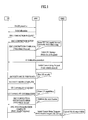
- FIG. 1 is a conceptual diagram illustrating a conventional delivery flow of the UE capability during the 'Attach' process of the UE. Detailed descriptions of FIG. 1 are as follows.
- the UE establishes a Radio Resource Control (RRC) connection.
- RRC Radio Resource Control
- the UE performs the RRC connection establishment by sending a message with a Random Access Channel (RACH) preamble to the eNode-B (eNB), receiving an initial allocation from the eNB, and sending a RRC CONNECTION SETUP message to the eNB.
- RACH Random Access Channel
- the UE transmits a RRC CONNECTION COMPLETE message to the eNB.
- the UE includes a NAS 'Attach Request' message in the RRC message.
- the eNode-B eNode-B
- the eNB transmits a S1 control message (i.e., initial UE message) having the NAS message (Attach Request) to the MME.
- the MME transmits the S1 control message (i.e., Initial Context Setup Request) to the eNode-B (eNB).
- S1 control message i.e., Initial Context Setup Request
- the eNode-B receives the 'Attach Accept' message from the MME.
- the eNode-B (eNB) carries out an initial security activation process including sending a SECURITY MODE COMMAND message to the UE and receiving a corresponding SECURITY MODE COMPLETE message from the UE.
- the eNode-B receives UE capability information from the UE by sending a UE CAPABILITY ENQUIRY message to the UE and receiving a corresponding UE CAPABILITY INFORMATION message from the UE.
- the eNode-B performs a RRC Connection Reconfiguration procedure using the received UE capability information, such that it acquires the latest UE capability from the UE.
- the eNode-B transmits a SI control message (Initial Context Setup Response) having the UE capability information to the MME.
- SI control message Initial Context Setup Response
- the UE capability is transferred to the network whenever the UE establishes the RRC connection.
- the UE supporting various wireless access technologies is introduced to the market and the UE function becomes more complex, the UE capability is gradually increasing.
- the conventional method for transferring a large amount of information to the network whenever the RRC connection is established unavoidably encounters unnecessary consumption of radio resources.
- the present invention is directed to a method for managing user equipment capabilities that substantially obviates one or more problems due to limitations and disadvantages of the related art.
- An object of the present invention is to provide a method for effectively managing UE capabilities over a network of a wireless communication system.
- Another object of the present invention is to provide a method for reducing an amount of radio resources needed for delivering the UE capability.
- Another object of the present invention is to provide a method for delivering the latest UE capability to a network only when the UE capability is changed.
- a method of managing user equipment (UE) capability at Mobility Management Entity (MME) of a network in a wireless communication system comprises: receiving a first status indication related to UE capability; determining whether or not a certain condition is satisfied using the first status indication; and selectively forwarding the UE capability to a base station or requesting the base station to obtain the UE capability in accordance with whether or not the certain condition is satisfied.
- UE user equipment
- MME Mobility Management Entity
- a method of obtaining user equipment (UE) capability in a wireless communication system comprising: receiving from the UE a status indication related to the UE capability; forwarding the status indication to Mobility Management Entity (MME) of a network; and receiving the UE capability from the MME, or performing a procedure to obtain the UE capability in accordance with a request from the MME.
- MME Mobility Management Entity
- Embodiments of the present invention have the following effects.
- an amount of radio resources needed for transferring the UE capability can be greatly decreased.
- the UE transfers its capability information only when the UE capability is changed, resulting in reduction of an amount of overhead encountered by the UE operation.
- the present invention reduces an amount of UE capability information communicated between networks, such that it can increase the efficiency of network resource usage.
- the network entity operation is limited to a message directly related to a corresponding layer, such that independency between AS and NAS layers can be maintained.
- FIG. 1 is a conceptual diagram illustrating a conventional method for transferring the UE capability during a network connection time
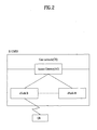
- FIG. 2 is a schematic diagram illustrating an Evolved - Universal Mobile Telecommunications System (E-UMTS) network according to the present invention
- FIG. 3 is a structural diagram illustrating an Evolved - Universal Terrestrial Radio Access Network (E-UTRAN) according to the present invention
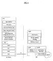
- FIG. 4 is a block diagram illustrating a logic architecture of typical network entities of the LTE system.
- FIG. 5 is a structural diagram illustrating a control plane of a Radio Interface Protocol between the UE and the E-UTRAN according to the present invention
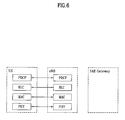
- FIG. 6 is a structural diagram illustrating a user plane of a Radio Interface Protocol between the UE and the E-UTRAN according to the present invention
- FIG. 7 is a flow chart illustrating a method for transferring the UE capability in case of 'Initial Attach' according to one embodiment of the present invention
- FIG. 8 is a flow chart illustrating a method for transferring the UE capability in case of 'Initial Attach' according to another embodiment of the present invention.
- FIG. 9 is a flow chart illustrating a method for managing the UE capability in case of 'Service Request' according to one embodiment of the present invention.
- FIG. 10 is a flow chart illustrating a method for managing the UE capability in case of 'Service Request' according to another embodiment of the present invention.
- FIG. 11 is a flow chart illustrating a method for managing the UE capability in case of 'Service Request' according to still another embodiment of the present invention.
- E-UMTS Evolved Universal Mobile Telecommunications System
- FIG. 2 shows a network structure of the E-UMTS to which an embodiment of the present invention is applied.
- the E-UMTS system is an evolved version of the conventional WCDMA UMTS system and basic standardization thereof is in progress under the 3rd Generation Partnership Project (3GPP).
- 3GPP 3rd Generation Partnership Project
- the E-UMTS is also referred to as a Long Term Evolution (LTE) system.
- LTE Long Term Evolution
- the E-UMTS includes a User Equipment (UE), a base station (or eNB or eNode-B), and an Access Gateway (AG) which is located at an end of a network (E-UTRAN) and which is connected to an external network.
- UE User Equipment
- base station or eNB or eNode-B
- AG Access Gateway
- an eNB can simultaneously transmit multiple data streams for a broadcast service, a multicast service and/or a unicast service.
- the AG can be divided into a part that processes of user traffic and a part that processes control traffic.
- the AG part for processing new user traffic and the AG part for processing control traffic can communicate with each other using an interface.
- One or more cells may exist for one eNB.
- An interface for transmitting user traffic or control traffic can be used between eNBs.
- a Core Network may include the AG and a network node or the like for user registration of the UE.
- An interface for discriminating between the E-UTRAN and the CN can be used.
- the AG manages mobility of a UE on a Tracking Area (TA) basis.
- One TA includes a plurality of cells.
- FIG. 3 illustrates a network structure of an Evolved Universal Terrestrial Radio Access Network (E-UTRAN) system which is a mobile communication system to which the embodiment of the present invention is applied.
- the E-UTRAN system is an evolved version of the conventional UTRAN system.
- the E-UTRAN includes a base station that will also be referred to as "eNode B" or "eNB".
- the eNBs are connected through an X2 interface.
- Each eNB is connected to the User Equipment (UE) through a radio interface and is connected to an Evolved Packet Core (EPC) through a S1 interface.
- the eNB and the EPC exchange S1 control messages through the S1 interface.
- UE User Equipment
- EPC Evolved Packet Core
- the S1 control message refers to a set of signaling messages between eNB and EPC (e.g., MME) to fulfill S1-AP functions, such as SAE Bearer management function, Initial Context Transfer function, UE Capability Info Indication function, Paging, NAS Signalling transport function between the UE and the MME is used, and so on.
- EPC e.g., MME
- S1-AP functions such as SAE Bearer management function, Initial Context Transfer function, UE Capability Info Indication function, Paging, NAS Signalling transport function between the UE and the MME is used, and so on.
- FIG. 4 is a block diagram illustrating an architecture of E-UTRAN and EPC.
- eNodeB may perform functions of selection for gateway, routing toward the gateway during a radio resource control (RRC) activation, scheduling and transmitting of paging messages, scheduling and transmitting of broadcast channel (BCCH) information, dynamic allocation of resources to UEs in both uplink and downlink, configuration and provisioning of eNodeB measurements, radio bearer control, radio admission control (RAC), and connection mobility control in LTE_ACTIVE state.
- RRC radio resource control
- BCCH broadcast channel
- gateway may perform functions of paging origination, LTE-IDLE state management, ciphering of the user plane, system architecture evolution (SAE) bearer control, and ciphering and integrity protection of non-access stratum (NAS) signalling.
- SAE system architecture evolution
- NAS non-access stratum
- the Mobility Management Entity is a kernel control node of the LTE access network.
- the MME performs tracking and paging of an UE in idle mode.
- the MME participates in a radio bearer activation/inactivation process.
- the MME takes charge of a serving gateway (SGW) selection associated with the UE.
- SGW serving gateway
- the MME performs UE authentication by interacting with a Home Subscriber Server (HSS).
- HSS Home Subscriber Server
- the NAS signaling is ended at the MME, and the MME generates a temporary identifier and allocates this temporary identifier to the UE.
- the MME determines whether or not the UE has a camp-on authority associated with a Public Land Mobile Network (PLMN) of a service provider.
- PLMN Public Land Mobile Network
- the MME is an end point for protecting the encryption/integrity for NAS signaling, and manages a security key.
- the MME provides a control plane function for the mobility between the LTE and the 2G/3G access network.
- FIGS. 5 and 6 illustrate the configurations of a control plane and a user plane of a radio interface protocol between a UE and a UMTS Terrestrial Radio Access Network (UTRAN) based on the 3GPP radio access network standard.
- the radio interface protocol is divided horizontally into a physical layer, a data link layer and a network layer, and vertically into a user plane for data transmission and a control plane for signaling.
- the protocol layers of FIGS. 5 and 6 can be divided into a L1 layer (first layer), a L2 layer (second layer) and a L3 layer (third layer) based on the lower three layers of the Open System Interconnection (OSI) reference model widely known in communication systems.
- OSI Open System Interconnection
- the control plane is a passage through which control messages that a UE and a network use in order to manage calls are transmitted.
- the user plane is a passage through which data (e.g., voice data or Internet packet data) generated at an application layer is transmitted.
- data e.g., voice data or Internet packet data
- the physical layer which is the first layer, provides an information transfer service to an upper layer using a physical channel.
- the physical layer is connected to a Media Access Control (MAC) layer, located above the physical layer, through a transport channel. Data is transferred between the MAC layer and the physical layer through the transport channel. Data transfer between different physical layers, specifically between the respective physical layers of transmitting and receiving sides, is performed through the physical channel.
- the physical channel is modulated according to the Orthogonal Frequency Division Multiplexing (OFDM) method, using time and frequencies as radio resources.
- OFDM Orthogonal Frequency Division Multiplexing
- the MAC layer of the second layer provides a service to a Radio Link Control (RLC) layer, located above the MAC layer, through a logical channel.
- RLC Radio Link Control
- the RLC layer of the second layer supports data transmission with reliability.
- the functions of the RLC layer may also be implemented through internal functional blocks of the MAC layer. In this case, the RLC layer need not be existed.
- a PDCP layer of the second layer performs a header compression function to reduce unnecessary control information in order to efficiently transmit IP packets such as IPv4 or IPv6 packets in a radio interface with a relatively narrow bandwidth.
- a Radio Resource Control (RRC) layer located at the lowermost of the third layer is defined only in the control plane and is responsible for control of logical, transport, and physical channels in association with configuration, reconfiguration and release of Radio Bearers (RBs).
- the RB is a service that the second layer provides for data communication between the UE and the UTRAN.
- the RRC layer of the UE and the RRC layer of the network exchange RRC messages.
- the UE is in RRC connected mode if RRC connection has been established between the RRC layer of the radio network and the RRC layer of the UE. Otherwise, the UE is in RRC idle mode.
- a Non-Access Stratum (NAS) layer located above the RRC layer performs functions such as session management and mobility management.
- the NAS layer exists in the MME of the UE and network.
- One cell of the eNB is set to use a bandwidth such as 1.25, 2.5, 5, 10 or 20MHz to provide a downlink or uplink transmission service to UEs.
- a bandwidth such as 1.25, 2.5, 5, 10 or 20MHz to provide a downlink or uplink transmission service to UEs.
- different cells may be set to use different bandwidths.
- Downlink transport channels for transmission of data from the network to the UE include a Broadcast Channel (BCH) for transmission of system information, a Paging Channel (PCH) for transmission of paging messages and a downlink Shared Channel (SCH) for transmission of user traffic or control messages.
- BCH Broadcast Channel
- PCH Paging Channel
- SCH downlink Shared Channel
- User traffic or control messages of a downlink multicast or broadcast service may be transmitted through a downlink SCH and may also be transmitted through a downlink multicast channel (MCH).
- Uplink transport channels for transmission of data from the UE to the network include a Random Access Channel (RACH) for transmission of initial control messages and an uplink SCH for transmission of user traffic or control messages.
- RACH Random Access Channel
- Logical channels which are located above the transport channels and are mapped to the transport channels, include a Broadcast Control Channel (BCCH), a Paging Control Channel (PCCH), a Common Control Channel (CCCH), a Multicast Control Channel (MCCH) and a Multicast Traffic Channel (MTCH).
- BCCH Broadcast Control Channel
- PCCH Paging Control Channel
- CCCH Common Control Channel
- MCCH Multicast Control Channel
- MTCH Multicast Traffic Channel
- the present invention provides a novel and improved mechanism of providing the UE capability information to the network, whereby the UE capability information is stored in the network and the stored UE capability information is reused as necessary.
- the UE capability information can be reused when the UE status is changed from the ECM-IDLE mode to the ECM-CONNECTED mode.
- the UE capability information may be stored in the Mobility Management Entity (MME) of the network.
- MME Mobility Management Entity
- the MME instead of the UE may provide the eNB with the UE capability information.
- the present invention includes a mechanism for determining whether the stored UP capability matches the present one of the UE. This is desirable in consideration of changeable characteristics of the UE capability.
- a representative example of the above-mentioned mechanism may be a status indicator associated with the UE capability.
- the term "status indicator” may be interchanged with "version indicator.”
- the UE may assign different status indicators to individual UE capabilities. In other words, the same status indicator indicates that the UE capability information is the same. Therefore, if the status indicator of the UE is equal to that of the network, the UE capability information of the network may be considered to be the present UE capability information.
- the status indicator owned by the UE may be called a first status indicator, and the other status indicator owned by the network may be called a second status indicator.
- the second status indicator may be stored in the MME. In other embodiments, the second status indicator may be stored in another location external to the UE.
- the status indicator may be a value tag.
- the method for changing a value of the value tag whenever the UE capability is changed to another can be used.
- the UE transmits the value tag to the network whenever a procedure for requesting the UE capability is carried out.
- a representative example of the above-mentioned requesting procedure is a 'Service Request' procedure.
- the 'Service Request' procedure is to transfer the EMM mode from EMM-IDLE to EMM-CONNECTED mode and establish the radio and S1 bearers when uplink user data is to be sent. This procedure is also to invoke MO/MT CS fallback procedures.
- the network compares a value tag received from the UE (i.e., a first value tag) with another value tag in the network (i.e., a second value tag). If the first value tag is different from the second value tag, the network determines that the stored UE capability information is not the present UE capability information.
- a value tag received from the UE i.e., a first value tag
- another value tag in the network i.e., a second value tag
- the UE capability information and the status indicator may be stored in the MME, but the comparison of the status indicators and the decision indicating whether the UE capability information stored in the network is reused can be carried out by either the eNB or the MME.
- the eNB requesting the above UE capability may be a serving eNB.
- the eNB receives a NAS first status indicator contained in the RRC message from the UE.
- the eNB receives the first status indicator from the NAS container.
- the eNB receives the UE capability information and a second status indicator from the MME.
- the eNB uses the UE capability information received from the MME.
- the eNB discards the UE capability information received from the MME, and requests the UE to send capability information.
- the MME receives a NAS first status indicator.
- the MME transmits the stored UE capability information to the eNB.
- the MME requests the eNB to obtain the UE capability information.
- deciding whether the UE capability information stored in the MME is the present one and deciding whether the stored information is reused can be carried out by each of the eNB and the MME.
- the above-mentioned procedure is carried out by the MME for the following first and second reasons.
- the first reason why it is preferable that the above-mentioned procedure is carried out by the MME is: if the eNB determines that the UE capability information stored in the MME is the latest information, the MME must transfer the UE capability information to the eNB although it does not recognize whether its own capability information is the latest or not. Therefore, if the eNB receives the UE capability information and the received UE capability information is not determined to be the latest information, the S1 interface resources are unnecessarily consumed.
- the MME determines that the UE capability information is the latest information, it provides the eNB with the UE capability information only when the stored UE capability information is the latest information. Therefore, the problem of generating the S1 interface resources unnecessarily consumed for transmitting unavailable UE capability information can be solved.
- the first reason why it is preferable that the above-mentioned procedure is carried out by the MME is: if the eNB determines that the UE capability information stored in the MME is the latest information, the eNB must read the status indicator contained in the NAS container of the RRC message received from the UE, such that it can carry out the comparison of the status indicators. If the eNB acting as the network entity associated with the AS layer checks contents of the NAS container between the UE and the MME, this checking operation cause damage to the independency between the AS layer and the NAS layer, such that it is considered to be ineffective.
- the MME determines whether the UE capability information is the latest information, the MME need not transfer a status indicator associated with the UE capability information to the eNB. Therefore, the eNB need not read the status indicator contained in the NAS container of the RRC message received from the UE, and guarantees the independency between the AS layer and the NAS layer.
- a method for transferring/reusing the UE capability information on the basis of the MME according to one embodiment of the present invention will hereinafter be described in detail.
- the present invention is not limited to only this specific case in which the UE performs the 'Attach' and 'Service Request' procedures.
- the present invention may also be applied to another procedure in which a network entity such as the eNB can download or receive the UE capability from the MME.
- the UE capability information associated with the UE may be invalid in the MME or may not exist in the MME. Therefore, during the 'Attach' procedure, although the UE capability information is stored in the MME, the UE capability information may be ignored and the latest capability information may be received from the corresponding UE. Therefore, the MME can manage/maintain the latest UE information. In more detail, during the 'Attach' procedure, the following cases 1 to 3 can be carried out.
- the capability information of the corresponding UE may be pre-stored in the MME.
- the conventional status indicator has been stored in the MME, it is assumed that the MME does not have the latest UE capability information in consideration of the 'Attach' procedure performed by the UE. Therefore, the MME requests the UE capability information from the eNB, and stores the UE capability information received from the UE.
- the capability information associated with the corresponding UE may be pre-stored in the MME.
- the stored status indicator is equal to the received status indicator, it is assumed that the MME does not have the latest UE capability information in consideration of the 'Attach' procedure performed by the UE. Therefore, the MME replaces the stored status indicator with the status indicator received from the UE. Thereafter, the MME requests the UE capability information from the eNB, and stores the received UE capability information received from the UE via the eNB.
- the MME may not have UE information of the corresponding UE. Since the MME has no UE capability information, it requests the UE capability information from the eNB, and stores the UE capability information received from the UE.
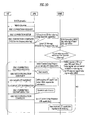
- FIG. 7 is a flow chart illustrating a method for transferring the UE capability in case of 'Initial Attach' according to one embodiment of the present invention.
- Steps 1) ⁇ 10 the 'Initial Attach' procedure is shown in the following Steps 1) ⁇ 10).
- Step 1) The UE establishes the RRC connection.
- the RRC connection establishment may be carried out by a random access procedure. For example, the UE transmits the RACH preamble, and the eNB allocates uplink resources to the UE in response to the preamble. Thereafter, the UE transmits the 'RRC CONNECTION REQUEST' message to the eNB, and the eNB transmits the 'RRC CONNECTION SETUP' message to the UE. If the RRC connection has been successfully established, the UE transmits the 'RRC CONNECTION COMPLETE' message to the eNB.
- the UE includes the NAS 'Attach Request' message in the 'RRC CONNECTION COMPLETE' message.
- Step 2) The eNB transmits a first S1 control message including the NAS 'Attach Request' message to the MME via the S1 interface.
- the first S1 control message may be an 'Initial UE Message' or a control message corresponding to this 'Initial UE Message'.
- the 'Initial UE Message' is a message sent by the eNB to transfer the initial layer 3 message to the MME over the S1 interface.
- the 'Initial UE Message' contains a NAS message (e.g. Attach Request, Service Request, etc.), the UE signalling reference ID and other S1 addressing information
- Step 3) The MME transmits a second S1 control message having the NAS 'Attach Accept' message to the eNB in response to the NAS 'Attach Request' message.
- the second S1 control message may be the 'Initial Context Setup Request' message or may be another control message corresponding to this 'Initial Context Setup Request' message.
- the 'Initial Context Setup Request' message is one of S1-AP control message sent by MMB to eNB during Initial Context Setup procedure.
- the purpose of the Initial Context Setup procedure is to establish the necessary overall initial UE Context including SAE Bearer context, Security context, Handover Restriction List, UE capability information, NAS-PDU etc.
- the procedure uses UE-associated signalling.
- Step 4) The eNB receives the second S1 control message having the NAS 'Attach Accept' message from the MME.
- Step 5 The eNB may transfer a message having the NAS 'Attach Accept' received from the MME to the UE.
- the message is used to transfer the NAS 'Attach Accept' from the MME to the UE. If the NAS 'Attach Accept' is transferred to the UE via another procedure, the above-mentioned message may be omitted.
- the above message may be the 'DL INFORMATION TRANSFER' message.
- the eNB may carry out an initial security activation procedure. In more detail, the eNB transfers the 'SECURITY MODE COMMAND' message to the UE. After performing the security activation according to the above message, the 'SECURITY MODE COMPLETE' message is transferred to the eNB.
- Step 6 Since the eNB has not received the UE capability information from the MME, it receives the capability information from the UE via the RRC procedure (i.e., UE Capability transfer RRC procedure) for transferring the UE capability.
- the eNB transmits the 'UE CAPABILITY ENQUIRY' message requesting the latest UE capability to the UE.
- the UE transmits the 'CAPABILITY INFORMATION' message having the latest UE capability information to the eNB in response to the above message.
- the 'CAPABILITY INFORMATION' message may include a value tag associated with the UE capability.
- Step 7) The eNB performs the RRC connection reconfiguration procedure using the received UE capability information.
- the eNB transmits the RRC CONNECTION RECONFIGURATION message to the UE, such that it can establish the radio bearer and command the RRC connection reconfiguration. If the NAS 'Accept Attach' message is transferred to the UE via the 'DL INFORMATION TRANSFER' message in the step 5), the RRC message may not have the NAS 'Accept Attach' message. Meanwhile, if the 'DL INFORMATION TRANSFER' message is not transferred at the step 5), the eNB includes the NAS 'Attach Accept' message received from the MME in the 'RRC CONNECTION RECONGIGURATION' message.
- the UE After completing the RRC connection reconfiguration, the UE transmits the 'RRC RECONFIGURATION COMPLETE' message to the eNB.
- the RRC message may have NAS 'Attach Complete' message which informs the MME of the success of the 'Attach' procedure.
- Step 8) The eNB transmits a third S1 control message having the NAS 'Attach Complete' message and the UE capability information to the MME via the S1 interface.
- the third S1 control message is a response to the second S1 control message received from the MME.
- the third S1 control message may be an 'Initial Context Setup Response' message or a control message corresponding to the 'Initial Context Setup Response' message.
- the 'Initial Context Setup Response' message is one of S1-AP control message sent by eNB to MME in response to the 'Initial Context Setup Request' during Initial Context Setup procedure.
- the third S1 control message may include the NAS 'Attach Complete' message received from the UE.
- Step 9) The MME considers the received UE capability information to be the latest information, and stores the latest information.
- Step 10 The MME considers a value tag contained in the UE capability information received from the eNB to be a desirable value tag corresponding to the latest UE capability, and stores this value tag.
- the corresponding UE capability and its value tag may be pre-stored in the MME at the step 3.
- the MME considers the UE performing the 'Initial Attach' procedure, such that it is determined that the UE capability information stored in the MME is not the latest information. Therefore, the MME performs the above-mentioned steps 5-10, such that it acquires the latest UE capability information and its value tag.
- steps 5 and 6 may be changed to another order according to encryption or decryption of the RRC message associated with the 'UE Capability transfer' procedure.
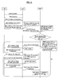
- FIG. 8 is a flow chart illustrating a method for transferring the UE capability in case of 'Initial Attach' according to another embodiment of the present invention. Except that the value tag associated with the UE capability information is initially and separately transferred, the remaining steps of FIG. 8 are basically identical with those of FIG. 7 . Referring to FIG. 8 , it can be seen that the steps 1-3 of FIG. 7 have been modified such that the UE initially transmits the value tag to the MME, and detailed description of the modification will hereinafter be described in detail. The following step 10 will be omitted.
- the UE establishes the RRC connection. If the RRC connection has been successfully established, the UE transmits the 'RRC CONNECTION COMPLETE' message to the eNB. The UE allows the RRC message to have the NAS 'Attach Request' message and the NAS value tag associated with the latest capability.
- the eNB transfers a first S1 control message including the NAS 'Attach Request' message and the NAS value tag to the MME via a first S1 interface.
- the MME in response to the NAS 'Attach Request', transfers a second S1 control message having the NAS 'Attach Accept' to the eNB via the S1 interface. Also, the MME stores the above value tag, and considers this value tag to be a desirable value tag associated with the latest UE capability acquired from the steps 4-9.
- the corresponding UE capability information may have or may have not been stored in the MME.
- the MME considers the 'Initial Attach' procedure, such that it requests the latest UE capability information from the eNB irrespective of the presence or absence of the UE capability.
- FIGS. 7 and 8 illustrate that the UE capability and its value tag are simultaneously stored. These figures illustrate the relationship between the UE capability and its value tag. Thus, FIGS. 7 and 8 do not mean to illustrate that the UE capability and the value tag should be simultaneously stored. The UE capability and the value tag may be simultaneously stored or be stored in different times according to their implementation examples.
- the UE capability information generally exists in the MME. If the eNB must recognize the UE capability and the MME has the latest UE capability information, the eNB may download (or receive) the corresponding UE capability from the MME and use the downloaded UE capability information. If the UE capability information owned by the MME is not the latest information or the MME does not have the UE capability information, the MME requests the latest UE capability information from the eNB.
- the MME receives a value tag from the UE (i.e., a first value tag)
- a value tag i.e., a second value tag
- the MME determines whether or not the stored value tag (i.e., a second value tag) exists in the MME. If the second value tag exists, it is determined whether the first value tag is identical with the second value tag. If any of the above conditions is not satisfied, the MME determines that the stored UE capability information is not the latest information. The MME replaces the second value tag with the first value tag, and requests the latest UE capability information from the eNB.
- the eNB Upon receipt of the above request, acquires the latest UE capability information from the UE, and transmits the acquired information to the MME.
- the eNB having received the above request from the MME transmits to the UE a command for indicating to transmit the capability information.
- the UE having received the command from the eNB transmits its own capability information to the eNB.
- the eNB transmits the capability information received from the UE to the MME.
- the MME considers the latest information of a corresponding UE and stores this latest UE information. If required, the above-mentioned capability information may simultaneously include a value tag associated with the capability information. In this case, the MME stores the value tag contained in the UE capability together with the latest capability information.
- FIG. 9 is a flow chart illustrating the 'Service Request' procedure performed when the MME has the latest UE capability information.
- the UE capability information stored in the MME is transferred to the eNB and is then re-used, and associated detailed descriptions will hereinafter be described.
- Step 1) The UE establishes the RRC connection. If the RRC connection has been successfully established, the UE transmits the 'RRC CONNECTION COMPLETE' message to the eNB.
- the UE allows the RRC message to have the NAS 'Service Request' message and the NAS value tag (i.e., first value tag) associated with the UE ability.
- the 'Service Request' message requests the MME to transfer the EMM mode from EMM-IDLE to EMM-CONNECTED mode and establish the radio and S1 bearers when uplink user data is to be sent.
- the 'Service Request' message also requests to invoke MO/MT CS fallback procedures
- Step 2) The eNB receives the RRC message, and transmits the NAS 'Service Request' message and the NAS value tag to the MME using the first S1 control message.
- the first S1 control message may be an 'Initial UE Message' or a control message corresponding to this 'Initial UE Message'.
- Step 3 The MME having received the NAS 'Service Request' from the eNB determines whether or not the UE capability can be reused when the presence of the stored UE capability is decided. In other words, the MME determines whether or not the value tag (i.e., second value tag) associated with the corresponding UE capability exists, and compares the first value tag with the second value tag. Since the first value tag is identical with the second value tag, the MME considers that the stored UE capability is the latest information. Thereafter, the MME transmits the stored UE capability information to the eNB via the second S1 control message.
- the second S1 control message may be the 'Initial Context Setup Request' message or another message corresponding to this 'Initial Context Setup Request' message.
- Step 4) The eNB receives the second S1 control message.
- Step 5 The eNB performs the initial security activation.
- the UE capability information downloaded from the MME can be used.
- Step 6 The eNB performs the RRC connection reconfiguration using the UE capability information downloaded from the MME.
- Step 7) The eNB transmits a third S1 control message to the MME via the S1 interface in response to the second S1 control message.
- the third S1 control message may be an 'Initial Context Setup Response' message or another control message corresponding to this 'Initial Context Setup Response' message.
- FIG. 10 is a flow chart illustrating a method for managing the UE capability in case of 'Service Request' according to another embodiment of the present invention.
- FIG. 11 is a flow chart illustrating a method for managing the UE capability in case of 'Service Request' according to still another embodiment of the present invention.
- FIGS. 10-11 illustrate scenarios where the UE capability information stored in the MME is not reused. A detailed description of FIGS. 10-11 follows. Steps common to FIGS. 10-11 are described once.
- Step 1) The UE establishes the RRC connection. If the RRC connection has been successfully established, the UE transmits the 'RRC CONNECTION COMPLETE' message to the eNB. The UE allows the RRC message to have the NAS 'Service Request' message and the NAS value tag (i.e., first value tag) associated with the UE ability.
- the NAS value tag i.e., first value tag
- Step 2) The eNB receives the RRC message, and transmits the NAS 'Service Request' message and the NAS value tag to the MME using the first S1 control message.
- the first S1 control message may be an 'Initial UE Message' or a control message corresponding to this 'Initial UE Message'.
- Step 3 The MME having received the NAS 'Service Request' from the eNB determines whether or not the UE capability can be reused when the presence of the stored UE capability is decided. In other words, the MME determines whether or not the stored value tag (i.e., second value tag) associated with the corresponding UE capability exists, and compares the first value tag with the second value tag. Since the first value tag is different from the second value tag, the MME considers that the stored UE capability is not the latest information. Therefore, the MME requests the latest UE capability information corresponding to the first value tag from the eNB.
- the stored value tag i.e., second value tag
- the MME is able to request the UE capability information in Step 3 using one of the following two methods i) ⁇ ii).
- the second S1 control message transferred to the eNB via the S1 interface may include a control command requesting the UE capability information.
- the second S1 control message may be an 'Initial Context Setup Request' message or a control message corresponding to the 'Initial Context Setup Request'.
- the control command requesting the UE capability information may be the 'UE CAPABILITY REQUEST'.
- the 'UE CAPABILITY REQUEST' is just an indicator sent by MME to indicate that eNB needs to fetch UE capability from the concerned UE and possibly to forward the information to the MME.
- the eNB having received the control command receives the latest capability information from the UE, and transfers the above capability information to the MME as shown in FIG. 10 .
- the second S1 control message transferred to the eNB via the S1 interface may not have the UE capability and the 'UE CAPABILITY REQUEST'.
- the second S1 control message may be the 'Initial Context Setup Request' message or a control message corresponding to this 'Initial Context Setup Request' message.
- requesting the latest UE capability from the eNB may be commanded by the second S1 control message having no UE capability and no 'UE Capability Request'.
- the eNB having received the second S1 control message receives the latest UE capability information, and transmits the received capability information to the MME as shown in FIG. 11 .
- Step 4) The eNB receives the second S1 control message from the MME.
- Step 5 The eNB performs the initial security activation.
- Step 6) The eNB receives a request from the MME in order to transmit the latest UE capability information to the MME, such that it receives the UE capability information via the RRC procedure (i.e., UE Capability transfer RRC procedure) transferring the UE capability.
- RRC procedure i.e., UE Capability transfer RRC procedure
- Step 7) The eNB performs the RRC connection reconfiguration using the UE capability information received from the UE.
- Step 8) The eNB allows the third S1 control message to have the UE capability information received from the UE, such that it transmits the resultant third S1 control message t the MME.
- the third S1 control message is a response to the second S1 control message received from the MME, and may be the 'Initial Context Setup Response' message or a control message corresponding to the 'Initial Context Setup Response' message.
- Step 9) The MME stores the received UE capability information, and considers the stored information to be the latest capability information.
- Step 10 The MME stores the value tag received simultaneously with the NAS 'Service Request' message, and considers that this stored value tag corresponds to the latest capability information.
- the UE capability information received from the eNB may have the value tag.
- the MME ignores the value tag received simultaneously with the 'Service Request' message, and considers that the value tag contained in the UE capability information corresponds to the latest UE capability information, and stores this value tag.
- the order of the steps 6 and 7 may be changed to another order according to encryption or decryption of the RRC message associated with the 'UE Capability transfer' procedure.
- FIGS. 9 to 11 illustrate that the UE capability and its value tag are simultaneously stored.
- FIGS. 9 to 11 illustrate the relationship between the UE capability and its value tag.
- the UE capability and the value tag may be simultaneously stored or be stored in different times according to their implementation examples.
- BS Base Station
- UE user equipment
- MS mobile station
- MS mobile station
- MSS mobile subscriber station
- the embodiments of the present invention can be implemented by hardware, firmware, software, or any combination thereof.
- the previously described UE, eNB and MME devices include one or more processors configured to execute the corresponding steps shown in FIGS 7-11 .
- the previously described UE, eNB and MME devices also include network interface devices and other communication modules.
- the previously described UE, eNB and MME devices may also include display and input devices or components.
- ASICs application specific integrated circuits
- DSPs digital signal processors
- DSPDs digital signal processing devices
- PLDs programmable logic devices
- FPGAs field programmable gate arrays
- processors controllers, microcontrollers, microprocessors, or the like.
- FIG. 1 Various the embodiments of the present invention may also be implemented in the form of software modules, processes, functions, or the like which perform the features or operations described above.
- Software code can be stored in a memory unit so that it can be executed by a processor.
- the memory unit may be located inside or outside the processor and can communicate data with the processor through a variety of known means.
- the present invention can be applied to a method for managing UE capabilities in a wireless communication system. More particularly, the present invention relates to a method for managing the UE capability by a Mobility Management Entity (MME) of a network in the wireless communication system.
- MME Mobility Management Entity
- an amount of radio resources needed for transferring the UE capability can be greatly decreased.
- the UE transfers its capability information only when the UE capability is changed, resulting in reduction of an amount of overhead encountered by the UE operation.
- the present invention reduces an amount of UE capability information communicated between networks, such that it can increase the efficiency of network resource usage.
- the network entity operation is limited to a message directly related to a corresponding layer, such that independency between AS and NAS layers can be maintained.
Landscapes
- Engineering & Computer Science (AREA)
- Databases & Information Systems (AREA)
- Computer Networks & Wireless Communication (AREA)
- Signal Processing (AREA)
- Mobile Radio Communication Systems (AREA)
Applications Claiming Priority (2)
| Application Number | Priority Date | Filing Date | Title |
|---|---|---|---|
| US1302107P | 2007-12-12 | 2007-12-12 | |
| KR1020080116391A KR101467795B1 (ko) | 2007-12-12 | 2008-11-21 | 단말 능력을 관리하는 방법 |
Publications (3)
| Publication Number | Publication Date |
|---|---|
| EP2071882A2 true EP2071882A2 (fr) | 2009-06-17 |
| EP2071882A3 EP2071882A3 (fr) | 2011-04-27 |
| EP2071882B1 EP2071882B1 (fr) | 2013-04-03 |
Family
ID=40451175
Family Applications (1)
| Application Number | Title | Priority Date | Filing Date |
|---|---|---|---|
| EP08021680A Not-in-force EP2071882B1 (fr) | 2007-12-12 | 2008-12-12 | Procédé de gestion des capacités d'équipement d'utilisateur dans un système de communication sans fil |
Country Status (2)
| Country | Link |
|---|---|
| US (1) | US9247420B2 (fr) |
| EP (1) | EP2071882B1 (fr) |
Cited By (18)
| Publication number | Priority date | Publication date | Assignee | Title |
|---|---|---|---|---|
| WO2011023095A1 (fr) * | 2009-08-25 | 2011-03-03 | 中兴通讯股份有限公司 | Procédé et système dallocation de ressources de liaison descendante |
| CN102045100A (zh) * | 2009-10-16 | 2011-05-04 | 中兴通讯股份有限公司 | 下行业务承载方法及下行业务发送装置 |
| WO2011109999A1 (fr) * | 2010-08-20 | 2011-09-15 | 华为技术有限公司 | Procédé d'indication de données et élément de réseau de gestion de mobilité |
| CN102696273A (zh) * | 2010-01-08 | 2012-09-26 | 富士通株式会社 | 载波聚合系统中载波管理的方法和装置 |
| CN102932765A (zh) * | 2011-08-12 | 2013-02-13 | 华为技术有限公司 | 能力信息获取的方法及设备 |
| EP2451220A4 (fr) * | 2009-07-03 | 2013-02-27 | Ntt Docomo Inc | Procédé de communication mobile, système de communication mobile, dispositif de serveur de gestion d abonnés et station d'échange |
| GB2498780A (en) * | 2012-01-26 | 2013-07-31 | Samsung Electronics Co Ltd | User equipment determines whether to report current state information to a radio access node |
| GB2498822A (en) * | 2012-01-26 | 2013-07-31 | Samsung Electronics Co Ltd | User equipment transmits a current value of state information to a radio access node if the radio access node does not hold the current value |
| US20140086173A1 (en) * | 2012-09-26 | 2014-03-27 | Interdigital Patent Holdings, Inc. | Methods, systems and apparatuses for operation in long-term evolution systems |
| CN103781124A (zh) * | 2012-10-26 | 2014-05-07 | 电信科学技术研究院 | 一种上行数据传输方法及用户设备 |
| EP2906011A4 (fr) * | 2012-10-04 | 2016-05-11 | Lg Electronics Inc | Procédé de fonctionnement basé sur un traitement d'informations de tolérance au retard dans un système de communication sans fil et appareil le prenant en charge |
| EP2549793A4 (fr) * | 2010-03-19 | 2017-02-15 | Alcatel Lucent | Procédé et système de communication de type machine, et procédé et dispositif de recherche de cellule |
| EP2600654A4 (fr) * | 2010-07-28 | 2017-05-24 | Kyocera Corporation | Station de base sans fil et son procédé de commande |
| US9681338B2 (en) | 2012-01-26 | 2017-06-13 | Samsung Electronics Co., Ltd. | Processing state information |
| CN108599814A (zh) * | 2012-10-05 | 2018-09-28 | 日本电气株式会社 | 无线电站、无线电终端及其方法 |
| US10111224B2 (en) | 2011-09-30 | 2018-10-23 | Interdigital Patent Holdings, Inc. | Device communication using a reduced channel bandwidth |
| CN108810876A (zh) * | 2017-05-05 | 2018-11-13 | 华为技术有限公司 | 通信方法及相关设备 |
| WO2021094083A1 (fr) * | 2019-11-13 | 2021-05-20 | British Telecommunications Public Limited Company | Procédé de configuration d'un réseau de télécommunications |
Families Citing this family (61)
| Publication number | Priority date | Publication date | Assignee | Title |
|---|---|---|---|---|
| CN101499967B (zh) * | 2008-02-03 | 2011-07-13 | 中兴通讯股份有限公司 | 电路域寻呼实现方法及系统 |
| GB2458885A (en) * | 2008-03-20 | 2009-10-07 | Nec Corp | Accepting or rejecting a connection request based upon capability information of a user device |
| EP2637442B1 (fr) * | 2008-03-21 | 2018-06-13 | Interdigital Patent Holdings, Inc. | Procédé et appareil pour permettre de revenir à un domaine à commutation de circuit depuis un domaine à commutation de paquet |
| US8515436B2 (en) * | 2008-03-27 | 2013-08-20 | Qualcomm Incorporated | Management of wireless connections |
| JP4511622B2 (ja) * | 2008-04-22 | 2010-07-28 | 株式会社エヌ・ティ・ティ・ドコモ | 移動通信方法、移動局及び無線基地局 |
| JP4511621B2 (ja) * | 2008-04-22 | 2010-07-28 | 株式会社エヌ・ティ・ティ・ドコモ | 移動通信方法、移動局及び無線基地局 |
| EP2324653B1 (fr) * | 2008-09-12 | 2019-10-23 | Nokia Technologies Oy | Orientation de capacité de matériel utilisateur |
| US8514793B2 (en) * | 2008-10-31 | 2013-08-20 | Interdigital Patent Holdings, Inc. | Method and apparatus for monitoring and processing component carriers |
| GB2464994A (en) * | 2008-11-04 | 2010-05-05 | Nec Corp | Communication system in which access control is dependent on mode of base station |
| CN101742692B (zh) * | 2008-11-07 | 2012-07-04 | 华为技术有限公司 | 寻呼处理、信息显示方法、装置 |
| CN101754398B (zh) * | 2008-12-16 | 2012-07-25 | 中兴通讯股份有限公司 | 长期演进系统中基站获取用户设备无线能力信息的方法 |
| US8615230B2 (en) * | 2008-12-19 | 2013-12-24 | Htc Corporation | Method of reporting radio access technology capability and related apparatus |
| PT2428069E (pt) | 2009-05-06 | 2015-02-06 | Ericsson Telefon Ab L M | Dispositivo de interligação dedicado para dispositivos de banda larga móvel |
| EP2477440A3 (fr) | 2009-09-18 | 2012-12-26 | NEC Corporation | Système de communication et procédé de commande de communication |
| JP5878123B2 (ja) * | 2009-09-27 | 2016-03-08 | ゼットティーイー コーポレーションZte Corporation | 状態遷移方法及び装置 |
| CN105764102A (zh) | 2009-10-30 | 2016-07-13 | 交互数字专利控股公司 | 用于执行电路交换回退的wtru |
| KR20110049622A (ko) * | 2009-11-04 | 2011-05-12 | 삼성전자주식회사 | 무선 통신 네트워크 시스템에서 데이터 전송 방법 및 장치 |
| AU2015200273B2 (en) * | 2010-01-08 | 2015-10-29 | Sony Corporation | Communication system for supporting carrier aggregation and method and apparatus for updating system information thereof |
| US10945302B2 (en) * | 2010-03-26 | 2021-03-09 | Interdigital Patent Holdings, Inc. | Managing race conditions between circuit switched fallback requests |
| JP4772910B1 (ja) * | 2010-04-05 | 2011-09-14 | 株式会社エヌ・ティ・ティ・ドコモ | 移動通信システムにおける基地局及び方法 |
| US9232544B2 (en) * | 2010-05-26 | 2016-01-05 | Telefonaktiebolaget L M Ericsson (Publ) | Connection states for a user entity in a serving gateway of an evolved packet core system |
| JP5031869B2 (ja) | 2010-06-21 | 2012-09-26 | 株式会社エヌ・ティ・ティ・ドコモ | 移動通信方法 |
| JP5982403B2 (ja) * | 2011-01-18 | 2016-08-31 | サムスン エレクトロニクス カンパニー リミテッド | 移動通信システムで端末の性能を報告する方法及び装置 |
| US9648657B2 (en) | 2011-04-01 | 2017-05-09 | Interdigital Patent Holdings, Inc. | Method and apparatus for controlling connectivity to a network |
| CN105392153B (zh) * | 2011-09-30 | 2018-05-11 | 日本电气株式会社 | 通信系统、方法和装置 |
| EP2772013B1 (fr) | 2011-10-27 | 2021-03-17 | Telefonaktiebolaget LM Ericsson (publ) | Mise en mémoire cache dans des réseaux de communication sans fil |
| WO2012163028A1 (fr) * | 2011-10-28 | 2012-12-06 | 华为技术有限公司 | Procédé de commande d'équipement d'utilisateur, procédé de commande d'une entité de gestion de la mobilité, équipement d'utilisateur, et entité de gestion de la mobilité et système de communication correspondants |
| US9432851B2 (en) * | 2011-12-20 | 2016-08-30 | Tejas Networks Limited | Bearer signalling management |
| CN103220657A (zh) * | 2012-01-20 | 2013-07-24 | 中兴通讯股份有限公司 | 一种获取终端能力信息的方法、系统及基站 |
| US20130195027A1 (en) * | 2012-01-30 | 2013-08-01 | Qualcomm Incorporated | Method and Apparatus for Channel Fallback in Enhanced Cell Forward Access Channel Dedicated Channel |
| CN102724759A (zh) * | 2012-04-10 | 2012-10-10 | 中兴通讯股份有限公司 | 无线承载配置方法及装置 |
| CN107071705B (zh) * | 2012-05-23 | 2021-02-23 | 华为技术有限公司 | 寻呼窄带终端的方法、网络设备、基站及系统 |
| EP2880909B1 (fr) * | 2012-08-02 | 2017-04-05 | Telefonaktiebolaget LM Ericsson (publ) | Noeligud et procédé pour fournir une interface entre des stations de base |
| CN104170486B (zh) * | 2012-08-15 | 2017-12-05 | 华为技术有限公司 | 终端能力上报的处理方法和系统及装置 |
| US9119182B2 (en) | 2012-10-19 | 2015-08-25 | Qualcomm Incorporated | Methods and apparatus for expression use during D2D communications in a LTE based WWAN |
| KR20140052397A (ko) * | 2012-10-24 | 2014-05-07 | 삼성전자주식회사 | 이동 통신 시스템에서 가상 머신 관리 장치 및 방법 |
| CN104937866B (zh) * | 2012-11-01 | 2018-03-23 | Lg 电子株式会社 | 在无线通信系统中收发参考信号的方法和设备 |
| US9807591B2 (en) * | 2013-03-29 | 2017-10-31 | Intel IP Corporation | Establishment of connection to the internet in cellular network |
| US20150085749A1 (en) * | 2013-09-26 | 2015-03-26 | Qualcomm Incorporated | Mechanism to exchange proprietary signaling messages between a ue and a network |
| JP5698822B1 (ja) * | 2013-10-25 | 2015-04-08 | 株式会社Nttドコモ | 移動通信方法、移動通信システム及び無線基地局 |
| KR102141621B1 (ko) * | 2013-11-05 | 2020-08-05 | 삼성전자주식회사 | 이동 통신 시스템에서 연결 재설정을 위한 장치 및 방법 |
| EP3101941B1 (fr) * | 2014-01-30 | 2019-10-23 | Nec Corporation | Station de base, terminal machine-machine (m2m), procédé et support lisible par ordinateur |
| CN106664549B (zh) * | 2014-08-15 | 2020-05-19 | 苹果公司 | 用于性能信息设置的演进节点b和用户设备的方法和装置 |
| US9585153B2 (en) * | 2014-12-18 | 2017-02-28 | Alcatel-Lucent Usa Inc. | Method and apparatus for improved carrier aggregation access control |
| US10327137B2 (en) * | 2015-03-16 | 2019-06-18 | Mavenir Systems, Inc. | System and method for detecting malicious attacks in a telecommunication network |
| GB2542770B (en) * | 2015-09-25 | 2020-01-08 | Samsung Electronics Co Ltd | Mobile device capability identifier |
| JP6598225B2 (ja) | 2016-01-05 | 2019-10-30 | 華為技術有限公司 | モバイル通信方法、装置、およびデバイス |
| US11109424B2 (en) * | 2016-04-01 | 2021-08-31 | Ntt Docomo, Inc. | Connection control method and connection control device |
| KR102148620B1 (ko) * | 2016-10-07 | 2020-08-26 | 츠-밍 처우 | 시스템 정보 전달을 위한 방법 및 장치 |
| CN106454804B (zh) * | 2016-11-21 | 2020-03-24 | 中国联合网络通信集团有限公司 | 一种获取终端能力的方法及装置 |
| US10588130B2 (en) * | 2017-02-03 | 2020-03-10 | Qualcomm Incorporated | Methods and apparatus for user equipment capability exchange |
| KR102174936B1 (ko) * | 2017-03-24 | 2020-11-05 | 주식회사 케이티 | 이종 네트워크에서의 단말의 이동성 제어 방법 및 그 장치 |
| EP3695682A4 (fr) * | 2017-10-10 | 2021-06-30 | Telefonaktiebolaget LM Ericsson (publ) | Transmission de données précoces à terminaison mobile |
| WO2020096963A1 (fr) * | 2018-11-05 | 2020-05-14 | Google Llc | Procédé de traitement d'une transition d'état de gestion de mobilité après repli vers un établissement de rrc |
| EP4451723B1 (fr) | 2019-01-15 | 2026-08-12 | Telefonaktiebolaget LM Ericsson (publ) | Capacités d'accès radio d'un dispositif sans fil |
| JP7404398B2 (ja) | 2019-05-01 | 2023-12-25 | ノキア テクノロジーズ オサケユイチア | データベース障害からの回復を含む最適化されたユーザ機器能力シグナリング |
| EP4024958A4 (fr) * | 2019-09-16 | 2022-08-17 | Huawei Technologies Co., Ltd. | Procédé et dispositif de transmission de données |
| WO2021087834A1 (fr) * | 2019-11-06 | 2021-05-14 | 华为技术有限公司 | Procédé et appareil d'interrogation d'informations de capacité |
| US12232166B2 (en) * | 2021-05-11 | 2025-02-18 | Qualcomm Incorporated | Narrowband random access channel occasions |
| US11985657B2 (en) * | 2021-10-01 | 2024-05-14 | Qualcomm Incorporated | Interleaved PUSCH transmissions |
| CN116017408B (zh) * | 2021-10-22 | 2026-01-30 | 华为技术有限公司 | 一种通信方法及通信装置 |
Family Cites Families (3)
| Publication number | Priority date | Publication date | Assignee | Title |
|---|---|---|---|---|
| US6912395B2 (en) * | 2001-09-25 | 2005-06-28 | Motorola, Inc. | Network and method for monitoring location capabilities of a mobile station |
| MY143277A (en) | 2006-03-20 | 2011-04-15 | Qualcomm Inc | Extended capability transfer between a user equipment and a wireless network |
| DK2218271T3 (en) * | 2007-12-06 | 2017-10-16 | ERICSSON TELEFON AB L M (publ) | PROCEDURE FOR UPDATING UE CAPACITY INFORMATION IN A MOBILE TELECOMMUNICATION NETWORK |
-
2008
- 2008-12-11 US US12/333,116 patent/US9247420B2/en not_active Expired - Fee Related
- 2008-12-12 EP EP08021680A patent/EP2071882B1/fr not_active Not-in-force
Cited By (46)
| Publication number | Priority date | Publication date | Assignee | Title |
|---|---|---|---|---|
| US8868073B2 (en) | 2009-07-03 | 2014-10-21 | Ntt Docomo, Inc. | Mobile communication method, mobile communication system, subscriber management server device, and mobile switching center |
| EP2451220A4 (fr) * | 2009-07-03 | 2013-02-27 | Ntt Docomo Inc | Procédé de communication mobile, système de communication mobile, dispositif de serveur de gestion d abonnés et station d'échange |
| WO2011023095A1 (fr) * | 2009-08-25 | 2011-03-03 | 中兴通讯股份有限公司 | Procédé et système dallocation de ressources de liaison descendante |
| CN102045100A (zh) * | 2009-10-16 | 2011-05-04 | 中兴通讯股份有限公司 | 下行业务承载方法及下行业务发送装置 |
| CN102696273A (zh) * | 2010-01-08 | 2012-09-26 | 富士通株式会社 | 载波聚合系统中载波管理的方法和装置 |
| CN102696273B (zh) * | 2010-01-08 | 2015-07-08 | 富士通株式会社 | 载波聚合系统中载波管理的方法和装置 |
| EP2549793A4 (fr) * | 2010-03-19 | 2017-02-15 | Alcatel Lucent | Procédé et système de communication de type machine, et procédé et dispositif de recherche de cellule |
| US9693335B2 (en) | 2010-07-28 | 2017-06-27 | Kyocera Corporation | Radio base station and method of controlling the same |
| EP2600654A4 (fr) * | 2010-07-28 | 2017-05-24 | Kyocera Corporation | Station de base sans fil et son procédé de commande |
| WO2011109999A1 (fr) * | 2010-08-20 | 2011-09-15 | 华为技术有限公司 | Procédé d'indication de données et élément de réseau de gestion de mobilité |
| CN102932765B (zh) * | 2011-08-12 | 2015-06-03 | 华为技术有限公司 | 能力信息获取的方法及设备 |
| CN102932765A (zh) * | 2011-08-12 | 2013-02-13 | 华为技术有限公司 | 能力信息获取的方法及设备 |
| WO2013023567A1 (fr) * | 2011-08-12 | 2013-02-21 | 华为技术有限公司 | Procédé et dispositif permettant d'acquérir des informations de capacité |
| US10111224B2 (en) | 2011-09-30 | 2018-10-23 | Interdigital Patent Holdings, Inc. | Device communication using a reduced channel bandwidth |
| US12120653B2 (en) | 2011-09-30 | 2024-10-15 | Interdigital Patent Holdings, Inc. | Device communication using a reduced channel bandwidth |
| US11582750B2 (en) | 2011-09-30 | 2023-02-14 | Interdigital Patent Holdings, Inc. | Device communication using a reduced channel bandwidth |
| US12143867B2 (en) | 2012-01-26 | 2024-11-12 | Samsung Electronics Co., Ltd. | Processing state information |
| US11647427B2 (en) | 2012-01-26 | 2023-05-09 | Samsung Electronics Co., Ltd. | Processing state information |
| US11044628B2 (en) | 2012-01-26 | 2021-06-22 | Samsung Electronics Co., Ltd. | Method and apparatus for processing state information in communication system |
| GB2498822A (en) * | 2012-01-26 | 2013-07-31 | Samsung Electronics Co Ltd | User equipment transmits a current value of state information to a radio access node if the radio access node does not hold the current value |
| US11510110B2 (en) | 2012-01-26 | 2022-11-22 | Samsung Electronics Co., Ltd. | Processing state information |
| US9681338B2 (en) | 2012-01-26 | 2017-06-13 | Samsung Electronics Co., Ltd. | Processing state information |
| GB2498780A (en) * | 2012-01-26 | 2013-07-31 | Samsung Electronics Co Ltd | User equipment determines whether to report current state information to a radio access node |
| US10728804B2 (en) | 2012-01-26 | 2020-07-28 | Samsung Electronics Co., Ltd. | Processing state information |
| GB2498780B (en) * | 2012-01-26 | 2014-12-17 | Samsung Electronics Co Ltd | Processing state information |
| US10708801B2 (en) | 2012-01-26 | 2020-07-07 | Samsung Electronics Co., Ltd. | Method and apparatus for processing state information in communication system |
| US10142873B2 (en) | 2012-01-26 | 2018-11-27 | Samsung Electronics Co., Ltd. | Method and apparatus for processing state information in communication system |
| US10264493B2 (en) | 2012-01-26 | 2019-04-16 | Samsung Electronics Co., Ltd. | Processing state information |
| GB2498822B (en) * | 2012-01-26 | 2015-01-07 | Samsung Electronics Co Ltd | Processing state information |
| US10420066B2 (en) | 2012-09-26 | 2019-09-17 | Interdigital Patent Holdings, Inc. | Methods, systems and apparatuses for operation in long-term evolution systems |
| US20140086173A1 (en) * | 2012-09-26 | 2014-03-27 | Interdigital Patent Holdings, Inc. | Methods, systems and apparatuses for operation in long-term evolution systems |
| US12309014B2 (en) | 2012-09-26 | 2025-05-20 | Interdigital Patent Holdings, Inc. | Methods, systems and apparatuses for operation in long-term evolution (LTE) systems |
| US9553701B2 (en) * | 2012-09-26 | 2017-01-24 | Interdigital Patent Holdings, Inc. | Methods, systems and apparatuses for operation in long-term evolution systems |
| US11076380B2 (en) | 2012-09-26 | 2021-07-27 | Interdigital Patent Holdings, Inc. | Methods, systems and apparatuses for operation in long-term evolution (LTE) systems |
| EP2906011A4 (fr) * | 2012-10-04 | 2016-05-11 | Lg Electronics Inc | Procédé de fonctionnement basé sur un traitement d'informations de tolérance au retard dans un système de communication sans fil et appareil le prenant en charge |
| CN108599814B (zh) * | 2012-10-05 | 2021-08-03 | 日本电气株式会社 | 无线电站、无线电终端及其方法 |
| CN108599814A (zh) * | 2012-10-05 | 2018-09-28 | 日本电气株式会社 | 无线电站、无线电终端及其方法 |
| CN103781124B (zh) * | 2012-10-26 | 2016-12-28 | 电信科学技术研究院 | 一种上行数据传输方法及用户设备 |
| CN103781124A (zh) * | 2012-10-26 | 2014-05-07 | 电信科学技术研究院 | 一种上行数据传输方法及用户设备 |
| CN113676896A (zh) * | 2017-05-05 | 2021-11-19 | 华为技术有限公司 | 通信方法及相关设备 |
| US11363648B2 (en) | 2017-05-05 | 2022-06-14 | Huawei Technologies Co., Ltd. | Communication method and related device |
| EP3611948A4 (fr) * | 2017-05-05 | 2020-02-19 | Huawei Technologies Co., Ltd. | Procédé de communication et dispositif associé |
| CN108810876A (zh) * | 2017-05-05 | 2018-11-13 | 华为技术有限公司 | 通信方法及相关设备 |
| US12219622B2 (en) | 2017-05-05 | 2025-02-04 | Huawei Technologies Co., Ltd. | Communication method and related device |
| WO2021094083A1 (fr) * | 2019-11-13 | 2021-05-20 | British Telecommunications Public Limited Company | Procédé de configuration d'un réseau de télécommunications |
| US20220417769A1 (en) * | 2019-11-13 | 2022-12-29 | British Telecommunications Public Limited Company | Method of configuring a telecommunications network |
Also Published As
| Publication number | Publication date |
|---|---|
| US20090170426A1 (en) | 2009-07-02 |
| EP2071882B1 (fr) | 2013-04-03 |
| US9247420B2 (en) | 2016-01-26 |
| EP2071882A3 (fr) | 2011-04-27 |
Similar Documents
| Publication | Publication Date | Title |
|---|---|---|
| US9247420B2 (en) | Method of managing user equipment capabilities | |
| US11889471B2 (en) | Paging time adjustment in a wireless network | |
| US12143916B2 (en) | Non-public network overload and congestion control | |
| US11963133B2 (en) | Core paging handling | |
| US12477330B2 (en) | Network slice specific authentication and authorization | |
| JP6685384B2 (ja) | 無線通信システムにおけるsiアップデート、eabアップデート及びpwsメッセージを通知するための方法及び装置 | |
| US9668240B2 (en) | Method of transmitting and receiving control information in a wireless communication system | |
| KR101455991B1 (ko) | 멀티미디어 브로드캐스트/멀티캐스트 서비스에서의 시스템정보 수신 방법 | |
| EP3338485B1 (fr) | Équipement utilisateur, station de base et procédés associés | |
| US8473003B2 (en) | Method and apparatus for receiving short message service (SMS) in dual mode terminal | |
| US8473639B2 (en) | Method and apparatus for performing non access stratum (NAS) procedure in multi-mode terminal | |
| KR20180136912A (ko) | 요청에 대한 응답 방법 및 네트워크 장치 | |
| US10028114B2 (en) | Method and apparatus for adaptive barring control for MO-SMS in wireless access system | |
| RU2414081C2 (ru) | Способ передачи сигналов в системе мобильной связи | |
| EP3193537B1 (fr) | Fonctionnement d'un dispositif de communication dans un réseau de communication mobile | |
| US11910488B2 (en) | Enhancement of feature support after interworking | |
| US20120281655A1 (en) | Method for managing component carrier setting information and a device for the same | |
| CN114642079B (zh) | 通信方法及装置 | |
| CN118828442A (zh) | 业务建立方法、装置、设备及介质 | |
| JP6513834B2 (ja) | 無線通信システムにおけるlte−wlanの調整を向上させるための方法及び装置 | |
| EP4322699A1 (fr) | Gestion d'accès lors de l'arrêt des temporisateurs de congestion 5gsm | |
| WO2008093997A1 (fr) | Procédé pour recevoir des informations système dans un servi e de diffusion-multidiffusion multimédia | |
| KR101467795B1 (ko) | 단말 능력을 관리하는 방법 |
Legal Events
| Date | Code | Title | Description |
|---|---|---|---|
| PUAI | Public reference made under article 153(3) epc to a published international application that has entered the european phase |
Free format text: ORIGINAL CODE: 0009012 |
|
| 17P | Request for examination filed |
Effective date: 20081212 |
|
| AK | Designated contracting states |
Kind code of ref document: A2 Designated state(s): AT BE BG CH CY CZ DE DK EE ES FI FR GB GR HR HU IE IS IT LI LT LU LV MC MT NL NO PL PT RO SE SI SK TR |
|
| AX | Request for extension of the european patent |
Extension state: AL BA MK RS |
|
| PUAL | Search report despatched |
Free format text: ORIGINAL CODE: 0009013 |
|
| AK | Designated contracting states |
Kind code of ref document: A3 Designated state(s): AT BE BG CH CY CZ DE DK EE ES FI FR GB GR HR HU IE IS IT LI LT LU LV MC MT NL NO PL PT RO SE SI SK TR |
|
| AX | Request for extension of the european patent |
Extension state: AL BA MK RS |
|
| AKX | Designation fees paid |
Designated state(s): DE FR GB |
|
| GRAP | Despatch of communication of intention to grant a patent |
Free format text: ORIGINAL CODE: EPIDOSNIGR1 |
|
| GRAS | Grant fee paid |
Free format text: ORIGINAL CODE: EPIDOSNIGR3 |
|
| GRAA | (expected) grant |
Free format text: ORIGINAL CODE: 0009210 |
|
| RAP1 | Party data changed (applicant data changed or rights of an application transferred) |
Owner name: LG ELECTRONICS INC. |
|
| AK | Designated contracting states |
Kind code of ref document: B1 Designated state(s): DE FR GB |
|
| REG | Reference to a national code |
Ref country code: GB Ref legal event code: FG4D |
|
| REG | Reference to a national code |
Ref country code: DE Ref legal event code: R096 Ref document number: 602008023396 Country of ref document: DE Effective date: 20130529 |
|
| PLBE | No opposition filed within time limit |
Free format text: ORIGINAL CODE: 0009261 |
|
| STAA | Information on the status of an ep patent application or granted ep patent |
Free format text: STATUS: NO OPPOSITION FILED WITHIN TIME LIMIT |
|
| 26N | No opposition filed |
Effective date: 20140106 |
|
| REG | Reference to a national code |
Ref country code: DE Ref legal event code: R097 Ref document number: 602008023396 Country of ref document: DE Effective date: 20140106 |
|
| REG | Reference to a national code |
Ref country code: FR Ref legal event code: PLFP Year of fee payment: 8 |
|
| PGFP | Annual fee paid to national office [announced via postgrant information from national office to epo] |
Ref country code: GB Payment date: 20151111 Year of fee payment: 8 Ref country code: DE Payment date: 20151111 Year of fee payment: 8 |
|
| PGFP | Annual fee paid to national office [announced via postgrant information from national office to epo] |
Ref country code: FR Payment date: 20151113 Year of fee payment: 8 |
|
| REG | Reference to a national code |
Ref country code: DE Ref legal event code: R119 Ref document number: 602008023396 Country of ref document: DE |
|
| GBPC | Gb: european patent ceased through non-payment of renewal fee |
Effective date: 20161212 |
|
| REG | Reference to a national code |
Ref country code: FR Ref legal event code: ST Effective date: 20170831 |
|
| PG25 | Lapsed in a contracting state [announced via postgrant information from national office to epo] |
Ref country code: FR Free format text: LAPSE BECAUSE OF NON-PAYMENT OF DUE FEES Effective date: 20170102 |
|
| PG25 | Lapsed in a contracting state [announced via postgrant information from national office to epo] |
Ref country code: DE Free format text: LAPSE BECAUSE OF NON-PAYMENT OF DUE FEES Effective date: 20170701 Ref country code: GB Free format text: LAPSE BECAUSE OF NON-PAYMENT OF DUE FEES Effective date: 20161212 |