EP2071909A1 - Tragbares endgerät und dünnschalen-verstärkungsstruktur - Google Patents
Tragbares endgerät und dünnschalen-verstärkungsstruktur Download PDFInfo
- Publication number
- EP2071909A1 EP2071909A1 EP07792955A EP07792955A EP2071909A1 EP 2071909 A1 EP2071909 A1 EP 2071909A1 EP 07792955 A EP07792955 A EP 07792955A EP 07792955 A EP07792955 A EP 07792955A EP 2071909 A1 EP2071909 A1 EP 2071909A1
- Authority
- EP
- European Patent Office
- Prior art keywords
- display section
- section side
- front case
- housing
- portable terminal
- Prior art date
- Legal status (The legal status is an assumption and is not a legal conclusion. Google has not performed a legal analysis and makes no representation as to the accuracy of the status listed.)
- Withdrawn
Links
- 230000003014 reinforcing effect Effects 0.000 title claims abstract description 11
- 229910052751 metal Inorganic materials 0.000 claims abstract description 35
- 239000002184 metal Substances 0.000 claims abstract description 35
- 238000005452 bending Methods 0.000 claims abstract description 20
- 239000000956 alloy Substances 0.000 claims 2
- 229910001092 metal group alloy Inorganic materials 0.000 claims 2
- 239000000463 material Substances 0.000 abstract description 23
- 239000000853 adhesive Substances 0.000 abstract description 14
- 230000001070 adhesive effect Effects 0.000 abstract description 14
- 239000007769 metal material Substances 0.000 abstract description 8
- 238000000034 method Methods 0.000 description 5
- 239000000758 substrate Substances 0.000 description 5
- 229910000861 Mg alloy Inorganic materials 0.000 description 4
- 239000011347 resin Substances 0.000 description 4
- 229920005989 resin Polymers 0.000 description 4
- 230000000694 effects Effects 0.000 description 3
- 238000001816 cooling Methods 0.000 description 2
- 239000004973 liquid crystal related substance Substances 0.000 description 2
- 230000015572 biosynthetic process Effects 0.000 description 1
- 238000004519 manufacturing process Methods 0.000 description 1
Images

Classifications
-
- H—ELECTRICITY
- H04—ELECTRIC COMMUNICATION TECHNIQUE
- H04M—TELEPHONIC COMMUNICATION
- H04M1/00—Substation equipment, e.g. for use by subscribers
- H04M1/02—Constructional features of telephone sets
- H04M1/18—Telephone sets specially adapted for use in ships, mines, or other places exposed to adverse environment
- H04M1/185—Improving the shock resistance of the housing, e.g. by increasing the rigidity
-
- H—ELECTRICITY
- H04—ELECTRIC COMMUNICATION TECHNIQUE
- H04M—TELEPHONIC COMMUNICATION
- H04M1/00—Substation equipment, e.g. for use by subscribers
- H04M1/02—Constructional features of telephone sets
- H04M1/0202—Portable telephone sets, e.g. cordless phones, mobile phones or bar type handsets
- H04M1/0206—Portable telephones comprising a plurality of mechanically joined movable body parts, e.g. hinged housings
- H04M1/0208—Portable telephones comprising a plurality of mechanically joined movable body parts, e.g. hinged housings characterized by the relative motions of the body parts
- H04M1/0214—Foldable telephones, i.e. with body parts pivoting to an open position around an axis parallel to the plane they define in closed position
- H04M1/0216—Foldable in one direction, i.e. using a one degree of freedom hinge
-
- H—ELECTRICITY
- H04—ELECTRIC COMMUNICATION TECHNIQUE
- H04M—TELEPHONIC COMMUNICATION
- H04M1/00—Substation equipment, e.g. for use by subscribers
- H04M1/02—Constructional features of telephone sets
- H04M1/0202—Portable telephone sets, e.g. cordless phones, mobile phones or bar type handsets
- H04M1/026—Details of the structure or mounting of specific components
- H04M1/0266—Details of the structure or mounting of specific components for a display module assembly
Definitions
- the present invention relates to a portable terminal equipment and a thin-type housing reinforcing structure for use in the same, in particular to a thin-type housing of a portable telephone.
- a portable terminal equipment is a portable terminal equipment including at least a plurality of housing parts, in which an L-shaped frame made of a metal plate is adhered and fixed on an internal surface of at least one housing part among the above a plurality of housing parts to be integrally with the one housing part, in addition, a bus-tab-shaped draw frame made of a metal plate is adhered and fixed on an external surface of the one housing part to be integrally therewith, the one housing part thereby has a sandwich structure.
- a thin-type housing reinforcing structure is a thin-type housing reinforcing structure for use in a portable terminal equipment including at least a plurality of housing parts, in which an L-shaped frame made of a metal plate is adhered and fixed on an internal surface of at least one housing part among the above a plurality of housing parts to be integrally with the one housing part, in addition, a bus-tab-shaped draw frame made of a metal plate is adhered and fixed on an external surface of the one housing part to be integrally therewith, the one housing part thereby has a sandwich structure.
- the portable terminal equipment of the present invention in a thin-size portable equipment such as a folding-type portable telephone, and the like, parts of metal plates made of highly rigid materials are adhered and fixed on internal, external surfaces respectively of a main housing formed of a metal capable of being formed, so that a sandwich structure is employed therein.
- a front case at a display section side, as a main housing at the display section side, of a thin-size folding-type portable telephone is made of a material of a metal, such as a magnesium alloy, and the like capable of being formed. Further, a bus-tab-shaped draw frame made of a metal plate is adhered and fixed on an external side of the front case at the display section side while two L-shaped frames each made of a metal plate are adhered and fixed on both side surfaced of an internal side of the front case at the display section side.
- the portable terminal equipment of the present invention has a sandwich structure, in which the parts of metal plates are adhered and fixed on internal, external surfaces respectively of the front case at the display section side as a main metal housing.
- This provides a thin-size folding-type portable telephone in which strength can be achieved.
- the front case of a frame shape at the display section side is formed of a metal material having strength.
- the bus-tab-shaped draw frame made by drawing a metal plate material is fixed on an external side of the front case at the display section side by the use of heat adhesive, thereby, the front case at the display section side and the bus-tab-shaped draw frame are rendered to be integral with each other.
- two L-shaped frames each made by bending a metal plate material are fixed on an internal side of the front case at the display section side by the use of two heat adhesives, thereby, the front case at the display section side and the L-shaped frames are rendered to be integral with each other.
- the two L-shaped frames and the bus-tab-shaped draw frame each made of a metal plate material reinforced by bending or drawing are thermally adhered and fixed on internal and external surfaces of the front case made of a metal material, such as a magnesium alloy, and the like, at the display section side.
- the portable terminal equipment of the present invention thereby has the sandwich structure, in which a plurality of parts are rendered to be integral with each other. Even if a portable terminal equipment, such as a folding-type portable telephone, and the like becomes a thin-type one, it is possible to drastically improve rigidity mainly against bending.
- the front case at the display section side is determined to have a minimum thickness thereof, so that a substrate on which LCD (Liquid Crystal Display) for display, LCD frame and electrical parts are mounted may be mounted on the front case at the display section side.
- a thickness obtained by a sum up of a deepness of drawing of the bus-tab-shaped draw frame and a height of bending of the L-shaped frame is contained within parts thickness of the front case at the display section side.
- the portable terminal equipment such as a folding-type portable telephone, and the like thereby can be made thin in size while achieving strength thereof.
- a portable terminal equipment according to the present invention has a structure described above.
- the portable terminal equipment can obtain an advantageous effect that rigidity mainly against bending can be improved drastically, even if the portable terminal equipment is made thin in size.
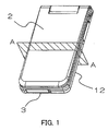
- Fig.1 is a perspective view for showing a closed condition of a portable terminal equipment according to an embodiment of the present invention
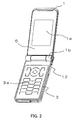
- Fig.2 is a perspective view for showing an opened condition of the portable terminal equipment according to the embodiment of the present invention.
- a thin-size folding-type portable telephone is shown as the portable terminal equipment in Figs. 1 and 2 .
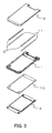
- Fig.3 is an exploded perspective view for showing main parts at a display section side of a thin-size folding-type portable telephone according to the embodiment of the present invention.
- Fig.4 is a cross sectional view along A-A line of Fig. 1 .
- Fig.5 is a detailed view for showing B section of Fig. 4 .
- a thin-size folding-type portable telephone 12 comprises a front case at a display section side 1 as a main housing at a display section side having a main display section 1a and a hinge section 1b, a rear cover at a display section side 2 which particularly depends on design factor, and a housing at an operation section 3 having a key operation section 3a, that are formed as main parts thereof.
- a bus-tab-shaped draw frame 4 made of a metal plate attached from an external side of the front case at the display section side 1 and two L-shaped frames 5 attached from an internal side of the front case at the display section side 1 are thermally adhered and fixed on the front case at the display section side 1 by the use of heat adhesives 10 and 11, respectively, so that the bus-tab-shaped draw frame 4, the two L-shaped frames 5 and the front case at the display section side 1 are rendered to be integral with each other and become one part of the thin-size folding-type portable telephone 12.
- a housing at a display section side of the thin-size folding-type portable telephone 12 comprises the front case at the display section side 1 and the rear cover at the display section side 2.
- the front case at the display section side 1 has the main display section 1a located in a major part of the front case at the display section side 1. Therefore, the front case at the display section side 1 is such a part that a strength thereof is required to a level capable of preventing the main display section 1a from being destroyed during an actual use. In addition, the front case at the display section side 1 is also such a part that complicated configurations are required in a portion fitted into the rear cover at the display section side 2, the hinge section 1b for being attached with a hinge, or the like. Therefore, a material of the front case at the display section side 1 is a metal material, such as a magnesium alloy, and the like capable not only of achieving strength of the front case at the display section side 1 but also of forming the complicated configurations thereof.
- the rear cover at the display section side 2 is positioned at an externally appearing portion of the thin-size folding-type portable telephone 12, even if the thin-size folding-type portable telephone 12 is set both in an opened condition and in a closed condition. Therefore, design characteristics are particularly important in the rear cover at the display section side 2.
- the rear cover at the display section side 2 is such a part that various designed configurations of appearance thereof are required. Therefore, a material of the rear cover at the display section side 2 is a resin material capable of readily forming the various configurations thereof.
- the front case at the display section side 1 of a frame shape is located on an appearance surface of an internal side of the thin-size folding-type portable telephone 12.
- a display screen window 6 is adhered by the use of a double-stick tape 6a and fixedly located on the front case at the display section side 1 to occupy a major part of the appearance thereof.
- an LCD(Liquid Crystal Display) for display 7 is located in the internal portion of the display screen window 6.
- the LCD for display 7 is contained and fixed in the bus-tab-shaped draw frame 4 thermally adhered and fixed with the front case at the display section side 1 together with an LCD frame 8.
- a substrate 9 on which electrical parts are mounted is located on another surface of the bus-tab-shaped draw frame 4 opposite to the surface on which the LCD frame 8 is contained.
- the rear cover at the display section side 2 is located at an external side of the substrate 9 to form an external appearance surface of the thin-size folding-type portable telephone 12.
- the bus-tab-shaped draw frame 4 and two L-shaped frames 5 are fixed on the front case at the display section side 1 by the heat adhesives to form one rigid body.
- the bus-tab-shaped draw frame 4 is made of a metal plate material capable of achieving strength, even if the metal plate material is thin. Further, the metal plate material is drawn to form a bus-tab-section 4a in the bus-tab-shaped draw frame 4 in order to increase strength thereof.
- Each of the L-shaped frames 5 is made of a metal plate material capable of achieving strength, even if the metal plate material is thin. Further, the metal plate material is bended like L-shape to form a bending section 5a in the L-shaped frame 5 in order to increase strength thereof.
- the bus-tab-shaped draw frame 4 is adhered and fixed on the appearance surface and the internal side surface of the front case at the display section side 1 by the heat adhesive 10 capable of being melted down by applying high temperature and of strongly being fixed by cooling. Further, two L-shaped frames 5 are also adhered and fixed on the internal surface and the internal side surface of the front case at the display section side 1 by the heat adhesive 11 capable of being melted down by applying high temperature and of strongly being fixed by cooling.
- the front case at the display section side 1, the bus-tab-shaped draw frame 4 and the two L-shaped frames 5 are strongly rendered to be integral with each other by the heat adhesives 10 and 11 to further increase strength of the parts.
- a thickness size of the bus-tab-section 4a as a deepness of drawing of the bus-tab-shaped draw frame 4 and a thickness size of the bending section 5a as a height of bending of the L-shaped frame 5 forms a thickness portion of the bus-tab-section 4a and a thickness portion of the bending section 5a within a thickness of the front case at the display section side 1, as illustrated in Fig. 5 . Therefore, as a thickness of the equipment, a thickness of sum of the thickness of the bus-tab-shaped draw frame 4 and the thickness of the L-shaped frame 5 can be held within the thickness of the front case at the display section side 1 as a main part, although making the metal plate be a shape of increased rigidity by drawing or bending. Consequently, a thin-type housing structure can be realized while achieving strength thereof.
- the front case at the display section side 1 of a frame shape is formed of a metal material having strength and further the bus-tab-shaped draw frame 4 formed by drawing the metal plate material is fixed at the external side of the front case at the display section side 1 by the heat adhesive 10.
- the front case at the display section side 1 and the bus-tab-shaped draw frame 4 are thereby rendered to be integral with each other.
- the two L-shaped frames 5 formed by bending the metal plate materials are fixed at the internal side of the front case at the display section side 1 by the two heat adhesives 11.
- the front case at the display section side 1 and the L-shaped frames 5 are thereby rendered to be integral with each other.
- the two L-shaped frames 5 and the bus-tab-shaped draw frame 4 each made of a metal plate material reinforced by bending or drawing are thermally adhered and fixed on internal and external surfaces of the front case at the display section side 1 formed of a metal material, such as a magnesium alloy, and the like.
- a plurality of parts, such as the front case at the display section side 1, the two L-shaped frames 5, and the bus-tab-shaped draw frame 4 are rendered to be integral with each other to have the sandwich structure.
- the front case at the display section side 1 is determined to have a minimum thickness thereof, so that the substrate 9 on which the LCD for display 7, the LCD frame 8 and the electrical parts are mounted may be mounted on the front case at the display section side 1.
- the thickness of sum of the deepness of drawing of the bus-tab-shaped draw frame 4 and the height of bending of the L-shaped frame 5 is held within the thickness of the front case at the display section side 1 as a main part. Consequently, the portable terminal equipment, such as the folding-type portable telephone, and the like can be a thin-type one while achieving strength thereof.
- the front case at the display section side 1 to have the sandwich structure in the above embodiment.
- the rear cover at the display section side 2 or the housing at the operation section 3 can also be formed to have the sandwich structure.
- the present invention can be applied to any housing parts of the portable terminal equipment, such as the folding-type portable telephone, and the like.
- the sandwich structure can also be applied to a plurality of main parts.
- a material of the front case at the display section side 1 is a metal material.
- the front case at the display section side 1 can also be made of a resin material.
- strength of the front case at the display section side 1 becomes lower than that of a case of the metal material.
- the front case at the display section side 1 made of the resin material brings a meritorious point that productivity of the front case at the display section side 1 can be improved.
- main housings and metal plate parts are fixed on each other by heat adhesives to form a sandwich structure. It can be considered that the main housings and the metal plate parts are fixed on each other not by the heat adhesives but by a double-stick tape, and the like. Further, if the other method of fixing brings similar effects, the other method can be used without a particular problem. Moreover, in the present invention, a fixing method in which the main housings and the metal plate parts are integrally formed by an insert formation can be considered.
- the present invention is a technique that can be mainly applied to a thin-size folding-type portable telephone.
- the present invention can also be applied to a thin-size portable terminal equipment, such as a PDA (Personal Digital Assistant), a note-type personal computer, and the like.
- PDA Personal Digital Assistant
Landscapes
- Engineering & Computer Science (AREA)
- Signal Processing (AREA)
- Telephone Set Structure (AREA)
Applications Claiming Priority (2)
| Application Number | Priority Date | Filing Date | Title |
|---|---|---|---|
| JP2006253652A JP5296970B2 (ja) | 2006-09-20 | 2006-09-20 | 携帯端末装置及びそれに用いる薄型筐体補強構造 |
| PCT/JP2007/066423 WO2008035537A1 (en) | 2006-09-20 | 2007-08-24 | Portable terminal and thin case reinforcing structure |
Publications (2)
| Publication Number | Publication Date |
|---|---|
| EP2071909A1 true EP2071909A1 (de) | 2009-06-17 |
| EP2071909A4 EP2071909A4 (de) | 2010-03-03 |
Family
ID=39200366
Family Applications (1)
| Application Number | Title | Priority Date | Filing Date |
|---|---|---|---|
| EP07792955A Withdrawn EP2071909A4 (de) | 2006-09-20 | 2007-08-24 | Tragbares endgerät und dünnschalen-verstärkungsstruktur |
Country Status (5)
| Country | Link |
|---|---|
| US (1) | US8554288B2 (de) |
| EP (1) | EP2071909A4 (de) |
| JP (1) | JP5296970B2 (de) |
| CN (1) | CN101518169B (de) |
| WO (1) | WO2008035537A1 (de) |
Cited By (2)
| Publication number | Priority date | Publication date | Assignee | Title |
|---|---|---|---|---|
| EP2388980A3 (de) * | 2010-05-19 | 2014-03-26 | LG Electronics Inc. | Mobiles Endgerät |
| EP2827564A4 (de) * | 2012-03-12 | 2015-10-28 | Nec Corp | Tragbares endgerät |
Families Citing this family (16)
| Publication number | Priority date | Publication date | Assignee | Title |
|---|---|---|---|---|
| US7697281B2 (en) | 2008-09-05 | 2010-04-13 | Apple Inc. | Handheld computing device |
| JP5039855B2 (ja) * | 2008-09-05 | 2012-10-03 | アップル インコーポレイテッド | ハンドヘルド演算装置 |
| CN102164989B (zh) | 2008-09-30 | 2013-11-27 | 三井化学株式会社 | 纤维增强树脂组合物及其成型体 |
| USD628971S1 (en) * | 2009-02-16 | 2010-12-14 | Doro AB | Mobile telephone |
| USD628177S1 (en) * | 2009-03-13 | 2010-11-30 | Nokia Corporation | Handset |
| KR100932177B1 (ko) * | 2009-08-31 | 2009-12-16 | (주)일신테크 | 열융착 테이프를 이용한 휴대단말기용 케이스 모듈 |
| USD626932S1 (en) * | 2009-10-09 | 2010-11-09 | Samsung Electronics Co., Ltd. | Mobile phone |
| JP2011090096A (ja) * | 2009-10-21 | 2011-05-06 | Panasonic Corp | 携帯端末装置 |
| USD622255S1 (en) * | 2010-03-03 | 2010-08-24 | Samsung Electronics Co., Ltd. | Cellular phone |
| USD635953S1 (en) * | 2010-07-30 | 2011-04-12 | Samsung Elctronics Co., Ltd. | Mobile phone |
| US8848351B2 (en) * | 2012-04-11 | 2014-09-30 | Shenzhen China Star Optoelectronics Technology Co., Ltd. | Frame for LCD device and LCD device |
| JP5941330B2 (ja) * | 2012-04-20 | 2016-06-29 | シャープ株式会社 | 携帯端末 |
| CN104854846B (zh) * | 2012-11-19 | 2017-06-30 | 日本电气株式会社 | 移动终端设备 |
| WO2016014047A1 (en) | 2014-07-23 | 2016-01-28 | Apple Inc. | Adaptive processes for improving integrity of surfaces |
| US10649497B2 (en) * | 2014-07-23 | 2020-05-12 | Apple Inc. | Adaptive processes for improving integrity of surfaces |
| KR20170064360A (ko) * | 2015-12-01 | 2017-06-09 | 삼성전자주식회사 | 휘어진 디스플레이를 포함하는 전자 장치 |
Family Cites Families (19)
| Publication number | Priority date | Publication date | Assignee | Title |
|---|---|---|---|---|
| JPH08298385A (ja) * | 1995-04-26 | 1996-11-12 | Oki Electric Ind Co Ltd | 筐体の防水構造 |
| JPH09123209A (ja) * | 1995-10-31 | 1997-05-13 | Toshiba Corp | 筐体装置 |
| JPH10256738A (ja) * | 1997-03-12 | 1998-09-25 | Nippon Steel Corp | 携帯用電子機器外枠 |
| SE512422C2 (sv) * | 1997-09-17 | 2000-03-13 | Volvo Ab | Lastbärande fordonstak och förfarande för dess tillverkning |
| JPH11154790A (ja) * | 1997-09-22 | 1999-06-08 | Toshiba Corp | 筐体装置とその製造方法 |
| US6318687B2 (en) * | 1998-08-31 | 2001-11-20 | Fluke Corporation | Accessory mount |
| US20020036902A1 (en) * | 2000-09-22 | 2002-03-28 | Lynch Peter F. | Portable lighting devices having a fabric housing portion |
| KR20040064271A (ko) * | 2001-11-09 | 2004-07-16 | 미네베아 가부시키가이샤 | 터치 패널 어셈블리 |
| US7130004B2 (en) * | 2002-03-04 | 2006-10-31 | Nokia Corporation | Display arrangement |
| JP4249943B2 (ja) * | 2002-05-31 | 2009-04-08 | 京セラ株式会社 | 携帯電子機器 |
| JP2004251938A (ja) * | 2003-02-18 | 2004-09-09 | Mitsubishi Electric Corp | Lcd表示パネル保護構造 |
| KR20040095814A (ko) * | 2003-04-28 | 2004-11-16 | 삼성전자주식회사 | 휴대용 전자기기의 디스플레이 장치 |
| KR100677298B1 (ko) * | 2003-05-12 | 2007-02-05 | 엘지전자 주식회사 | 휴대용 단말기의 커버 교체장치 |
| JP4187158B2 (ja) * | 2003-07-17 | 2008-11-26 | 京セラ株式会社 | 携帯型電子機器 |
| JP4364699B2 (ja) * | 2004-03-30 | 2009-11-18 | 富士通株式会社 | 折畳み式電子装置 |
| JP3850847B2 (ja) * | 2004-06-28 | 2006-11-29 | 株式会社東芝 | 電子機器の液晶表示装置保護構造 |
| CN2779807Y (zh) * | 2005-01-18 | 2006-05-10 | 上海迪比特实业有限公司 | 一种悬绳装置 |
| KR100652748B1 (ko) * | 2005-07-19 | 2006-12-01 | 엘지전자 주식회사 | 엘시디모듈 및 이를 구비한 이동통신 단말기 |
| US7620175B2 (en) * | 2006-07-24 | 2009-11-17 | Motorola, Inc. | Handset device with audio porting |
-
2006
- 2006-09-20 JP JP2006253652A patent/JP5296970B2/ja not_active Expired - Fee Related
-
2007
- 2007-08-24 US US12/442,217 patent/US8554288B2/en not_active Expired - Fee Related
- 2007-08-24 EP EP07792955A patent/EP2071909A4/de not_active Withdrawn
- 2007-08-24 WO PCT/JP2007/066423 patent/WO2008035537A1/ja not_active Ceased
- 2007-08-24 CN CN2007800348677A patent/CN101518169B/zh not_active Expired - Fee Related
Cited By (3)
| Publication number | Priority date | Publication date | Assignee | Title |
|---|---|---|---|---|
| EP2388980A3 (de) * | 2010-05-19 | 2014-03-26 | LG Electronics Inc. | Mobiles Endgerät |
| US8761836B2 (en) | 2010-05-19 | 2014-06-24 | Lg Electronics Inc. | Mobile terminal |
| EP2827564A4 (de) * | 2012-03-12 | 2015-10-28 | Nec Corp | Tragbares endgerät |
Also Published As
| Publication number | Publication date |
|---|---|
| CN101518169A (zh) | 2009-08-26 |
| US20100041449A1 (en) | 2010-02-18 |
| EP2071909A4 (de) | 2010-03-03 |
| US8554288B2 (en) | 2013-10-08 |
| JP2008078838A (ja) | 2008-04-03 |
| JP5296970B2 (ja) | 2013-09-25 |
| WO2008035537A1 (en) | 2008-03-27 |
| CN101518169B (zh) | 2011-08-10 |
Similar Documents
| Publication | Publication Date | Title |
|---|---|---|
| EP2071909A1 (de) | Tragbares endgerät und dünnschalen-verstärkungsstruktur | |
| EP1612594B1 (de) | Flüssigkristallanzeigemodul | |
| US10990128B2 (en) | Portable information apparatus having a display | |
| JP5090710B2 (ja) | 携帯電子機器 | |
| EP2262203B1 (de) | Flüssigkristallanzeigemodul und tragbares Endgerät | |
| US20100203924A1 (en) | Electronic Device and Mobile Phone | |
| JP5216342B2 (ja) | シールドケース及び電子機器 | |
| JP5963272B2 (ja) | 情報端末 | |
| CN109460113B (zh) | 一种柔性显示屏组件和电子设备 | |
| EP2541311A1 (de) | Anzeigevorrichtung | |
| CN100377035C (zh) | 显示单元和便携式电子设备 | |
| KR20110127483A (ko) | 휴대용 단말기 | |
| US20040077385A1 (en) | Foldable electronic device | |
| CN116567120B (zh) | 中框、中框的加工方法和电子设备 | |
| JP2015219387A (ja) | 表示装置 | |
| US8107259B2 (en) | Portable electronic device | |
| US8489155B2 (en) | Portable electronic apparatus | |
| EP2189965B1 (de) | Elektronische vorrichtung und rahmenelement dafür | |
| US20100134968A1 (en) | Mobile terminal device | |
| EP2141976A2 (de) | Gehäuse | |
| JP2002314262A (ja) | 電子機器筐体 | |
| US9474173B2 (en) | Portable terminal | |
| JP4547322B2 (ja) | 携帯通信機器 | |
| JP2009194031A (ja) | 電子機器 | |
| JP2007226285A (ja) | 携帯電子機器 |
Legal Events
| Date | Code | Title | Description |
|---|---|---|---|
| PUAI | Public reference made under article 153(3) epc to a published international application that has entered the european phase |
Free format text: ORIGINAL CODE: 0009012 |
|
| 17P | Request for examination filed |
Effective date: 20090331 |
|
| AK | Designated contracting states |
Kind code of ref document: A1 Designated state(s): AT BE BG CH CY CZ DE DK EE ES FI FR GB GR HU IE IS IT LI LT LU LV MC MT NL PL PT RO SE SI SK TR |
|
| A4 | Supplementary search report drawn up and despatched |
Effective date: 20100129 |
|
| RIC1 | Information provided on ipc code assigned before grant |
Ipc: H05K 5/04 20060101ALI20100125BHEP Ipc: H04M 1/02 20060101AFI20100125BHEP |
|
| DAX | Request for extension of the european patent (deleted) | ||
| RBV | Designated contracting states (corrected) |
Designated state(s): DE FR GB IT |
|
| STAA | Information on the status of an ep patent application or granted ep patent |
Free format text: STATUS: THE APPLICATION HAS BEEN WITHDRAWN |
|
| 18W | Application withdrawn |
Effective date: 20161115 |